ISSN: 2278-7461, www.ijeijournal.com
Volume 1, Issue 5 (September2012) PP: 26-30
Controller Reference Model
Parameter Adjustment Mechanism
DC MOTOR M ω
d ω Va
Uc
Controller Reference Model
Parameter Adjustment Mechanism
DC MOTOR M ω
d ω Va
Uc
Adaptive PID Controller for Dc Motor Speed Control
A.Taifour Ali
1, Eisa Bashier M. Tayeb
2and Omar Busati alzain Mohd
31,2School of Electrical and Nuclear Engineering; College of Engineering;
Sudan University of Science &Technology; SUDAN
3
M.Sc. at School of Electrical and Nuclear Engineering
Abstract––This investigation is concerned with the model reference adaptive PID control (MRAPIDC). Incorporating separately excited DC motors, subjected to uncertainties including parameter variations and ensuring optimum efficiency. The idea is to find further perfection for MRAC method and to provide an even more smooth control to the DC motor and to minimize deficiencies of the traditional MRAC method. This is examined when combining the MRAC method with the PID control. The performance of the drive system obtained, formed a set of test conditions with MRAPIDC. To achieve these objectives the simulation environment is provided in the MATLAB Simulink.
Keywords––Adaptive PID, Model Reference Adaptive Control (MRAC), Model Reference Adaptive PID Control (MRAPIDC), DC Motor Speed Control.
I.
INTRODUCTION
The Direct Current (DC) motors have variable characteristics and are used extensively in variable-speed drives. DC motor can provide a high starting torque and it is also possible to obtain speed control over a wide range. There are many adaptive control techniques, among them is the MRAC. It is regarded as an adaptive servo system in which the desired performance is expressed in terms of reference model. Model Reference Adaptive Control method attracting most of the interest due to its simple computation and no extra transducers is required [1-4]. The PID controller has several important functions; it provides feedback, has the ability to eliminate steady state offsets through integral action, and it can anticipate the future through derivative action. PID controllers are the largest number of controllers found in industries sufficient for solving many control problems [5]. Many approaches have been developed for tuning PID controller and getting its parameters for single input single output (SISO) systems. Among the well-known approaches are the Ziegler-Nichols (Z-N) method, the Cohen-Coon (C-C) method, integral of squared time weighted error rule (ISTE), integral of absolute error criteria (IAE), internal-model-control (IMC) based method, gain-phase margin method [6-14]. Adaptive control use to change the control algorithm coefficients in real time to compensate for variations in environment or in the system itself. This paper deals with the model reference adaptive control approach MRAC [15-18]. In which the output response is forced to track the response of a reference model irrespective of plant parameter variations.
II.
SYSTEM
DESCRIPTION
AND
MODELING
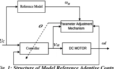
When the plant parameters and the disturbance are varying slowly or slower than the dynamic behavior of the plant, then a MRAC control can be used. The model reference adaptive control scheme is shown in figure 1. The adjustment mechanism uses the adjustable parameter known as control parameter
to adjust the controller parameters [4]. The tracking error and the adaptation law for the controller parameters were determined by MIT Rule [19].Fig. 1: Structure of Model Reference Adaptive Control
MIT (Massachusetts Institute of Technology) Rule is that the time rate of change of θ is proportional to negative gradient of the cost function (
J
), that is:(1)
J
The adaptation error
y
p(
t
)
y
M(
t
)
. The components of d d are the sensitivity derivatives of the error withrespect to the adjustable parameter vector
. The parameterγ
is known as the adaptation gain. The MIT rule is a gradientscheme that aims to minimize the squared model error
ε
2from cost function [20]:(2)
A. Modeling of DC Motor: The plant used in simulation is seperatly excited dc motor with dynamic equations as [21]:
(3)
(4)
(5)
Taking Laplace transform of equations (4) and (5), the transfer function of the DC motor with no load torque and uncertainties (
d
0
) is obtained from let TL= 0:(6)
First let us consider the case with only load disturbances TL≠ 0
(7)
B. Model Reference Adaptive PID Control: The goal of this section is to develop parameter adaptation laws for a PID control algorithm using MIT rule.
The reference model for the MRAC generates the desired trajectoryyM, which the DC motor speed yP has to follow. Standard second order differential equation was chosen as the reference model given by:
(8)
Consider also the adaptive law of MRAC structure taken as the following form [22]: (9)
Where; , Kp is proportional gain, Ki is integral gain, Kd is derivative gain and uc is a unit step input. In the Laplace domain, equation (9) can be transformed to:
(10)
It is possible to show that applying this control law to the system gives the following closed loop transfer function:
(11)
Apply MIT gradient rules for determining the value of PID controller parameters (K*P,K*iand K*d). The tracking error
equation (8) satisfies:
(12)
The exact formulas that are derived using the MIT rule can not be used. Instead some approximations are required. An approximation made which valid when parameters are closed to ideal value is as follows [23]:
Denominator of plant
Denominator model reference then, from gradient method. (13))
(
)
(
21 2t
J
] ) ( ) ( [ 1 2 JL K K R B s JL BL JR s J s JL R T d a b a m a a a a a L L U L d
d
d
)
(
)
(
)
(
t
I
t
R
L
K
t
V
dt bdi a a
a
L dt
d a
m
I
t
B
t
J
t
T
K
(
)
(
)
(
)
]
[
)
(
)
(
) ( ) ( 2 a b m a a a a a m JL K K BR JL BL JR JL Ks
s
s
V
s
) ( 0 1 2 M M M M a s a s b s H
(
)
(
)
(
)
)
(
t
K
Pe
t
K
ie
t
dt
K
de
*t
y
Pu
d P
i
P E sK y
s K E K U
C P d P
i P P
P u y sK y
s K K G Y M d P i P P P C i P P P Y K G s K G K G s U K G s K G 2 ) 1 ( K Y Y J K J dt dK i
J
Then the approximate parameter adaptation laws are as follows: (14)
(15)
(16)
III.
SIMULATION
RESULTS
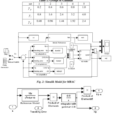
In this section, some simulation carried out for MRAC Separately Excited DC motor controller. Matlab software was used for the simulation of control systems. Fig 2 shows Simulik models for both MRAC along with the motor under control. While Fig.3 shows implementation of MIT rule to obtain adaptation gains. The parameters of separately excited DC motor are considered as:
55
.
0
bm
K
K
; Ra 1; La 0.046H2
. 093 .
0 Kgm
J ;
B
0
.
08
Nm
/
s
/
rad
. Also, the second order transfer function of the Model Reference as follows:This reference model has 16% maximum overshoot, settling time of more than two seconds and rise time of about 0.45 seconds. In simulation, the constants gammas were grouped in five sets as in table 1:
Table 1: Groups of Gammas
set 1 2 3 4 5
p
0.2 0.4 0.6 0.8 1.0i
0.8 1.6 2.4 3.2 4.0d
0.48 0.96 1.44 1.92 2.4Fig. 2: Simulik Model for MRAC
Fig. 3: Simulik Model for Proportional Adaptation Gain (MIT rule) 2
1 2 0 *
e a s a s a
s s
K
m m p
p
1
2 1 2 0 *
e a s a s a s K
m m i
i
2 1 2 0
2 *
P m m d
d Y
a s a s a
s s
K
16 4 16 2
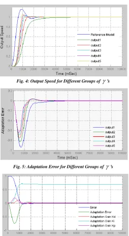
Fig. 4: Output Speed for Different Groups of
’sFig. 5: Adaptation Error for Different Groups of
’sFig. 6: Error, Adaptation Error and Adaptation PID Gains
As shown in Fig. 4 for low adaptation gains, the actual speed has no oscillation but too much delay, so poor performance. Increasing adaptation gains the output speed response improved towards matching the desired speed value of model reference. The adaptation error is shown in Fig. 5, while Fig. 6 sows the error, adaptation error and adaptation gains for certain group of gammas. As results the MRAPIDC achieves satisfactory performance. The transient performance specifications are shown in table 2. These simulations show that MRAPIDC requires less information of the process at the same time achieves good performances.
Table 2: Characteristic Values for no Load Speed
Specifications Sets of Gammas
1 2 3 4 5
Rise Time (sec) 1.15 0.71 0.54 0.46 0.44
Settling Time (sec) 3.2 1.34 1.46 1.29 1.42
IV.
CONCLUSION
From the simulation results, it is found that the MRAPIDC achieves satisfactory performance the output speed response of the DC motor. The adaptation gains are responsible to improve the transient performance of the speed response in terms of rise time, overshoot, settling time and steady-state for step speed response.
REFERENCES
1. Hans Butler, Ger Honderd, and Job van Amerongen “Model Reference Adaptive Control of a Direct-Drive DC Motor” IEtE Control Systems Magazine, 1989, pp 80-84.
2. S. Vichai, S. Hirai, M. Komura and S. Kuroki “Hybrid Control-based Model Reference Adaptive Control” lektronika Ir Elektrotechnika, Nr. 3(59) (2005) pp 5-8.
3. Chandkishor, R. ; Gupta, O. “Speed control of DC drives using MRAC technique” 2nd International Conference on Mechanical and Electrical Technology (ICMET) Sep 2010, pp 135 – 139.
4. Missula Jagath Vallabhai, Pankaj Swarnkar, D.M. Deshpande “Comparative Analysis Of Pi Control And Model Reference Adaptive Control Based Vector Control Strategy For Induction Motor Drive” IJERA Vol. 2, Issue 3, May-Jun 2012, pp 2059-2070.
5. Eisa Bashier M. Tayeb and A. Taifour Ali “Comparison of Some Classical PID and Fuzzy Logic Controllers” Accepted for publication in International Journal of Scientific and Engineering Research; likely to be published in
Vol 3, Issue 9, September 2012. (IJSER - France).
6. J. G. Ziegler and N. B. Nichols, “Optimum settings for automatic controllers,” Transactions of American Society of Mechanical Engineers, 1942, Vol. 64.
7. G. H. Cohen and G. A. Coon, “Theoretical investigation of retarded control,” Transactions of American Society of Mechanical Engineers, 1953, Vol. 75.
8. M. Zhuang and D. P. Atherton, “Automatic tuning of optimum PID controllers,” IEE Proceedings on Control and Applications, 1993, Vol. 140.
9. D. W. Pessen, “A new look at PID-controller tuning,” Journal of Dynamical Systems Measures and Control, 1994, Vol. 116.
10. M. Morari and E. Zafiriou "Robust Process Control" Prentice-Hall, Englewood Cliffs, 1989, New Jersey.
11. W. K. Ho, C. C. Hang, and L. S. Cao, “Tuning of PID controllers based on gain and phase margin specifications,”
Automatica, 1995, Vol. 31.
12. P. Cominos, N. Munro. PID Controllers: Recent Tuning Methods and Design to Specification. in: IEE Proceedings, Control Theory and Applications, 2002, vol. 149, 46–53.
13. C. Lee. A Survey of PID Controller Design based on Gain and Phase Margins. International Journal of Computational Cognition, 2004, 2(3): 63–100.
14. G. Mann, B. Hu, R. Gosine. Time Domain based Design and Analysis of New PID Tuning Rules. IEE proceedings, Control Theory Applications, 2001, 148(3): 251–261.
15. K.H. Chua, W.P. Hew, C.P. Ooi, C.Y. Foo and K.S. Lai “A Comparative Analysis of PI, Fuzzy Logic and ANFIS Speed Control of Permanet Magnet Synchoronous Motor”ELEKTROPIKA: Int. J. of Electrical, Electronic Engineering and Technology, 2011, Vol. 1, 10-22.
16. Pankaj Swarnkar, Shailendra Jain and R. K. Nema “Effect of Adaptation Gain in Model Reference Adaptive Controlled Second Order System” ETASR - Engineering, Technology & Applied Science Research Vol. 1, _o.3,
2011, 70-75.
17. K. Benjelloun, H. Mechlih, E. K. Boukas, “A Modified Model Reference Adaptive Control Algorithm for DC Servomotor”, Second IEEE Conference on Control Applications, Vancouver, B. C., 1993, Vol. 2, pp. 941 – 946. 18. K. J. Astrom, Bjorn Wittenmark “Adaptive Control”, 2nd Ed. Pearson Education Asia, 2001, pp. 185-225. 19. Stelian Emilian Oltean and Alexandru Morar, "Simulation of the Local Model Reference Adaptive Control of the
Robatic Arm with DC Motor Drive, Medimeria Science, 3, 2009.
20. A. Assni , A. Albagul, and O. Jomah “Adaptive Controller Design For DC Drive System Using Gradient Technique” Proceedings of the 2nd
International Conference on Maritime and Naval Science and Engineering pp 125 -128.
21. Faa-Jeng Lin, “Fuzzy Adaptive Model-Following Position Control for Ultrasonic Motor”, IEEE Transactions on Power Electronics, 1997, Vol. 12. pp 261-268.
22. Hang-Xiong Li, "Approximate Model Reference Adaptive Mechanism for Nominal Gain Design of Fuzzy Control System", IEEE transactions on systems. Man, and Cybernetics Society, 1999, Vol. 29. pp41-46.