41
Volume 65 5 Number 1, 2017
https://doi.org/10.11118/actaun201765010041
THE UTILISATION OF SOLAR SYSTEM IN
COMBINED HEATING SYSTEM OF WATER
Ján Jobbágy
1, Koloman Krištof
1, Pavol Findura
1, Oľga Urbanovičová
1,
Milan Križan
11 Department of Machines and Production Biosystems, Faculty of Engineering, Slovak University of Agriculture in Nitra, Tr. A. Hlinku 2, 949 76 Nitra, Slovakia
Abstract
JOBBÁGY JÁN, KRIŠTOF KOLOMAN, FINDURA PAVOL, URBANOVIČOVÁ OĽGA, KRIŽAN MILAN. 2017. The Utilisation of Solar System in Combined Heating System of Water. Acta Universitatis Agriculturae et Silviculturae Mendelianae Brunensis, 65(1): 0041–0050.
The paper assessed the topicality and returns of solar system utilization to heating of water. Practical measurements were conducted after reconstruction of the family house. (in Nesvady, Slovak republic), on which the solar system were assembled. The system consists of the gas heater, solar panels, distributions and circulation pump. The solar system was assembled due to decreasing of operation costs and connected with conventional already used gas heating system by boiler Quantum (V = 115 L). The conventional system was used for 21 days to gather basic values for evaluation. At this point it was observed that 11.93 m3 of gas is needed to heat up 1 m3 of water. Used water in this
case was heated from initial 16.14 °C to 52.04 °C of output temperature. Stand by regime of boiler was characterized by 0.012 m3.h-1 consumption of gas. The rest of the measurements represent
the annual (from 03/2013 to 02/2014) operation process of boiler Tatramat VTS 200L (trivalent) with 200 litres of volume (as a part of Thermosolar solar system). The solar collectors TS 300 are also part of the solar system. An input and output temperatures of heating water we observed along with water and gas consumption, intensity of solar radiation and actual weather conditions. The amount of heat produced by solar system was then calculated. Total investment on solar system were 2,187.7 € (1,475.7 € with subsidy). Therefore, return on investment for the construction of the solar system was set at 23 years even with subsidy.
Keywords: solar system, solar collectors, alternative energy, energy savings, solar energy costs
INTRODUCTION
The solar energy is defined as the energy which falls at earth surface in form of solar radiation. This energy is a product of thermonuclear reactions in Sun and delivered to the Earth in form of electromagnetic radiation. This energy from Sun is the most important source of energy for biosphere and it means for all form of life on Earth, our civilization including (Murtinger, Truxa, 2010).
Solar energy can meet three distinct applications: heating water, heating air, and generation of electricity in any residential or commercial setting. In most cases, solar energy provides the lowest lifecycle cost, and the lowest environmental impact from the release of greenhouse gases (Boone, 2015).
hot water load met by solar) (EIA, 2009). SWHs use radiation from the sun to heat solar collectors, and then transfer that heat to water. As in conventional storage tank water heating systems, SWH systems also store the heated water for future use. Because hot water demand is typically greater in the morning or late evening and does not coincide with times of maximum solar radiation, an SWH system is normally supplemented with a conventional system that provides additional heating as necessary. Most residential SWH systems contain five basic components: Solar thermal collector(s) [flat-plate and evacuated tube collectors are the most typical]; Storage system [to meet the thermal energy demand when solar radiation is not available]; Heat transfer system [piping and valves for liquids; pumps, fans, and heat exchangers (HXs), if necessary]; Control system [to manage the collection, storage, and distribution of thermal energy] and Auxiliary storage tank to provide supplemental heat when solar energy is not sufficient to meet demand (Hudon et al., 2007).
This kind of solar heating system was applied on observed house. The aim of the study was to assess the effective utilisation of solar system for heating of the water.
MATERIALS AND METHODS
Design of the heating system
The solar system was implemented into already functional system of water heating by commonly used gas heater. After the installation the device for water heating were developed combining both solar energy and energy based on gas combustion. Water heated by solar energy was led into the gas heater which was in stand by regime. In case of insufficient amount of heated water from solar boiler the gas heater automatically heats the water at required temperature. To heat water, thus contribute also
solar collectors, circulating pump, distributions and solar heater Tatramat VTS 200L. Orientation of the house with a part where the collectors are installed was to the west-southwest. The implementation scheme of a solar system is shown in Fig. 1.
Flat-plate collectors (collector TS 300) designed for solar systems are also equipped with additional circulation pump and installed under a particular gradient (Fig. 2). Two collectors are connected in parallel with flanged brass pins which are connected to hydraulic circuit by quick couplings with diameter of 26 mm. The design is compact pressed box of Al-Mg metal sheet which is fitted with safety solar glass by a frame from not corrodible aluminium sections. The absorber is a shaped aluminium sheet with selective conversion layer which surrounds the copper pipe meander. Flexible pipeline (16mm diameter) - corrugated stainless pipe with isolation and reinforced protective PE film.
Solar boiler Tatramat VTS 200L (trivalent) is designed to be used in combination with solar collectors, heating by electricity or heating by hot water boilers. Hot water in boiler is heated by solar heat exchanger preferentially. In case of insufficient input from a solar heating system, circulating water can be warmed to the desired temperature by heating water from boiler or electrical heating rod.
I: Technical parameters of boiler
Parameter Value
Tank volume, l 115
Input power, kW 8
Output power, kW 6,9
Heating time ∆t=25 °C, min 31
Gas consumption G20, m3.h-1 0,87
Gas consumption G30, kg.h-1 0,66
Max. input water pressure, MPa 1
Nominal input gas pressure, kPa 2 (gas G20), 3 (gas G30)
Thermoregulation range, °C 30-70
Overall height, mm 1200
Overall diameter, mm 495
Flue gas pipe diameter, mm 81
Closed expansion steel tank with a rubber cushion serves to compensate the pressure in case of stagnate temperature of solar collector. The rubber cushion is recommended to pressurize on 2.5 to 3 kPa before fulfilling of the system. The dimensioning of the expansion tank depends on the total volume of liquid in the device and output heat power. It connects directly to solar system. The volume of the expansion tank was 12 l.
Two-way pump unit is connected into the input and output branches of the solar circuit (pump
Grundfos SOLAR 25-60-130 mm). Another part of the unit is also a safety valve equipped by manometer and thermometer, flow meter, pressure hose, filling and discharge valve, manual air valve and set of the liquid overflow from the safety valve.
Regulator DC 12 (Thermosolar) is bound to the methods used by the hydraulic schemes (program restrictions of regulatory levels). It controls the circulation pump by variable speed via the graphical display. With additional equipment allows calculating and displaying the amount of 1: Implemented solar system
1 – solar boiler, 2 – circulating pump, 3 – expansion tank, 4 – gas heater with tank 115 L, 5 – solar collectors, 6 – manual air vent valve
II: Technical parameters of solar collectors
Parameter Value
Ground area, m2 2.03
Absorption area, m2 1.78
Weight, kg 36.1
Volume of liquide, l 1.57
Maximum overpressure, kPa 600
Recommended flow, l.h-1 30-100
Cover glass Solar security glass, thickness 4 mm
Collector box Metal sheet (Al-Mg)
Thermal isolation Mineral felt
Selectively conversion layer ALOx (black), Eta plus (blue)
Thermal emissivity e82°C 13% (ALOx), 5% (Eta plus)
Optical efficiency, % 81
Recommended operating temp., °C under 100
Min. annual energy gain from 1m2 area, kWh.m-2.year-1 525
Type of collector TS 300
Reference surface for efficiency absorptive
Optimal efficiency C0, % 81.2
Linear coefficient C1, W.m-2.K-1 3.63
Quadratic coefficient C2, W.m-2.K-2 0.011
Stagnant temp., °C 190
obtained energy and efficiency of solar system. It works in combination with two temperature sensors. The first is allocated at the solar collector and measure the temperature of circulating liquid. The second is allocated inside of the solar boiler. The supporting structure is made of aluminium profiles without surface treatment.
Measurement of parameters of the solar system with a backup gas heating
For evaluation of the effective utilisation of the solar system a group of input and output parameters were selected which serves as a basis for following calculations. The measurements were collected for whole cycle of year (12 months).
Specific weather data were received from Slovak Hydrometeorological Institute (SHMI). Intensity of solar radiation was collected from neighbouring farm.
• The database of input values consists of following parameters:
• Temperature of the collector absorber, • Temperature of water inside the solar boiler, • Temperature of water at output of the solar boiler, • Temperature of water at input of the solar boiler, • Temperature of water at output of the gas heater, • Consumption of water,
• Consumption of gas,
• Temperature inside the heating room.
Parameter Value
Volume, l 200
Heating method Electric, solar, circulating hot water
Tank pressure, MPa 1
Input power, kW 2
Switch-off temperature, °C 60
Heating time (15 to 60 °C), min 270
Active area of exchanger, m2 0.92
Exchanger of liquid volume, l 5.8
Output power (heat – solar), kW 22.5
2: Pump unit and support structure of collectors
The temperatures of individual streams were measured by thermometer Watts (Bella pumps with accuracy of measurement ± 2 %, Fig. 3). The thermometers were installed into the pipes directly. The gas consumption was measured by gas meters working on membrane principles (Fig. 3, with accuracy of measurement ± 3 %). Those gas meters are devices for measurement of volume in which the flow chambers are designed to secure optimal flow conditions with minimum of pressure lose. All of them are approved for measurement of gas consumption by PTB and fulfil certification by EN 1359 by DVGW. Consumption of water was measured by water flow meter Sensus (Fig. 4, with accuracy of measurement ± 5 %).
Daily measurements were recorded into the database in the same time intervals. Energy gains Q (MJ; or divided by coefficient 3.6 to get results in kWh) from solar boiler were then calculated by following formula:
(
6
. . .
,
10
k zsolar
c V t t
Q
=
ρ
−
MJ
(1)where:
c – Specific heat = 4186 J.kg-1.K-1 ρ – Water density = 1000 kg.m-3
V – Tank volume (200 l = 0.2 m3),
tk – Final temperature of tank, tz– Starting temperature of tank.
Measurement of parameters of the heating by gas
In this case the measurements were conducted without solar system engagement and the same parameters were recorded as mentioned before. Regulator of the solar system was disconnected from power supply which means that the flow of circulating water was not heated inside the solar boiler. It results into the measurement of gas consumption on heated water unit by gas specifically.
RESULTS AND DISCUSSION
Surveys demonstrate that solar water heaters belong under advanced technologies, but on the other hand, are not among the most effective in relation to the cost. Input costs without grants from the government are still high and are among the biggest disadvantages of its usage. Further and modern research has leads to significant advances in materials (design and possibilities of their production) which can help reduce still high input costs of solar water heaters. Further improvements can be made by increasing of the performance and by facilitate of the installation works. Thus, if we summarize all of the inputs the existing solar water heating systems are significantly more expensive (price + installation) as the commonly used systems for heating water. In most of the cases it is almost 10 times more.
IV: Overview of input costs – water heating by solar energy
Component, parameter Cost, €
Flexible pipe – stainless and isolated DN 16.3 m 162.75
Double fastener for flexible pipes 5.20
Heat transfer fluid SOLAREN-EKO/kg 47.95
Matrix G3/4” DN 16 7.15
Bolt GA 3/4” DN 16 1.02
Reduction G 3/4” R22x1.5 12.66
Insert from brass D3/4” 2.62
Sealant 3/4” 24/16 Temasil 26.20
Boiler 200L solar VTS trivalent 458.83
Expansion tank Solarvarem 23.03
Temperature regulator with microprocessor DC 12 90.23
Collector TS 300 (P CFT) 636.94
Assembly set - expanded TS 300 (P) 4.43
Assenbly set – basic TS 300 pr.22 22.94
Safety venting set 14.07
Set of the liquid overflow from the safety valve 3.66
SIJ-Rgusol two-way with vent out valve L130 220.23
Assembly set/70 sloping roof 2 collectors BAO 98.49
Total costs without VAT, € 1838.40
Total costs including VAT, € 2187.70
house during which was introduced the modern heating unit – solar system for heating of water. Solar system was linked to already existing system using gas in order to reduction of input costs for gas boiler. During measurements and following evaluation of input parameters without engagement of solar system it was found that roughly 11.91 m3
of gas is needed for heating of 1 m3 of water (Fig. 4).
It is also important to note that the water was necessary to be warm from the input temperature (16.14 °C) to the output temperature (52.04 °C).
represents 0.012 m3.h−1.
Solar system was developed from many components as it was described in material and methods chapter. Total investments required for this system are summarized in table 4. Input and output parameters (listed in the methodology) of the solar system were recorded for 12 months.
Two graphical evaluations were produced. Firstly (Fig. 5, Fig. 6), the comparison of the gas consumption for heating of 1 m3 of water (Q
gas) and
the amount of heat from solar collectors (Qsolar).
0.008 0.040 0.200 1.000 5.000
1 2 3 4 5 6 7 8 9 10 11 12 13 14 15 16 17 18 19 20
C
ons
um
pt
io
n,
m
3
Time, day
Gas consumption Water consumption
4: Consumption of gas and water – without solar system
0.002 0.008 0.040 0.200 1.000 5.000 25.000 125.000
1 3 5 7 9 11 13 15 17 19 21 23 25 27 29
QGa
s
, m
3
Qsol
ar
, kW
h
Time, day
Gas consumption per water of 1 m3 Qsolar
The results showed the trend of increasing (linear function: y = 0.3162x + 7.4046; R2 = 0.1712)
consumption of gas at decreasing (linear function: y = −0.007x + 0.263; R² = 0.3015) income amount of heat from the solar collectors, however, both trends were found to be not statistically significant due to calculated R2. The beginning of measurement was
in March. The average outside temperature was 6.58 °C. From the point of weather conditions whole month was mostly cloudy with average intensity of solar radiation (100.66 W.m-2). As it is visible from
Fig. 6 the lowest solar energy gain was recorded at 26th day of measurement (0.005 kWh = 0.018 MJ).
This lowest solar energy gain (Fig. 5) is in contrast to daily solar radiation intensity (Fig. 6) and the energy requirements were compensated by the increased gas consumption (Fig. 5). The temporary solar energy gain decrease was caused by partial shading of surface of the solar collectors, according to measurement logs.
The average temperature of solar collectors was 19.4 °C. The water consumption in selected month represents 2.45 m3 and gas consumption
was 24.12 m3. Solar system heats the water from
input temperature 11.2 °C to output temperature 26.8 °C. To amalgamate, the solar system produced 4.66 kWh = 8.82 MJ in March (average 0.155 kWh. day-1 = 0.558 MJ.day-1) and it was consumed about
12.31 m3 of gas (to heat up 1 m3 of water from input
to output temperature).
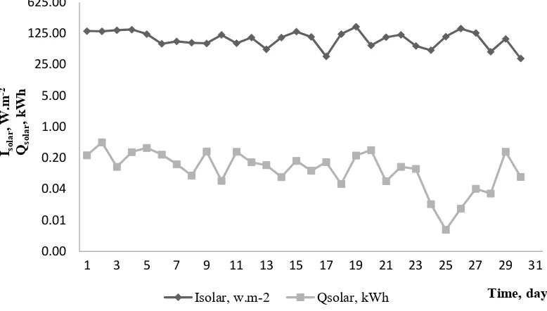
Secondly (Fig. 6), the comparison of daily solar radiation intensity Isolar and the amount of heat from
solar system (Qsolar). It shows the average values of
daily solar radiation intensity. If the intensity of solar radiation has increased then the output of solar energy has increased as well, however, statistically significant correlation was not observed. The values
of solar radiation intensity range from 34.39 to 177.06 W.m-2.
In April, specifically in its second half, increase in the amount of heat generated by solar system appears. The extreme value was observed in 4th day
of this month (Qsolar = 0.068 kWh.day-1 = 0.2448 MJ.
day-1, gas consumption = 0.861 m3. day-1).
The total heat generated by solar system delivered into the process of water heating represents 11.635 kWh = 41.886 MJ (with average in April 0.388 kWh.day-1 = 1.3969 MJ.day-1). In comparison
with March there were observed lower gas consumption, specifically 6.45 m3 of gas which
means reduction about 5.86 m3. Intensity of
solar radiation ranged from 41.19 to 260.89 W.m-2
(average 189.15 W.m−2). Next month (May) was
quite variable. The values of heat generated from solar collectors range from 0.018 to 0.87 kWh; 0.0648 and 3.132 MJ, respectively (average value from May was 0.37 kWh.day-1 = 1.332 MJ.day−1).
Extreme value (Qsolar = 0.018 kWh = 0.0648 MJ)
in this month despite of clear weather
(Isolar = 215.99 W. m−2) was observed at 4th day
because of water consumption 0.0004 m3 only.
The gas consumption in the mentioned day was only 0.056 m3 which means that the gas heater
was working only in standby regime. In 6th month
(Jun) there were two extremes observed, at 1st
and 28th day (1st day: Q
gas = 20.78 m3.day-1, 28th day:
Qgas = 15.84 m3.day-1). The average value of gas
consumption was 0.392 m3.day-1 (gas consumption
for whole month was 11.75 m3). In this month
a total amount of heat generated by solar collectors
(Qsolar) was reduced to 9.24 kWh = 33.264 MJ
(average 0.308 kWh = 1.1088 MJ) in comparison with May where Qsolar = 11.46 kWh = 41.256 MJ
(average 0.37 kWh = 1.332 MJ). Next two months
0.00 0.01 0.04 0.20 1.00 5.00 25.00 125.00 625.00
1 3 5 7 9 11 13 15 17 19 21 23 25 27 29 31
Isolar
, W .m -2 Qsol ar , kW h Time, day
Isolar, w.m-2 Qsolar, kWh
as it was expected. In July, there were observed a gas consumption of 3.2 m3 (during first 10 days of
month) and in August 2.51 m3 (during last 5 days of
month). For those two months the gas heater was completely disengaged. The reason was a suspicion to high energy losses, which was unfortunately confirmed. The gas heater implemented in this particular system is not able to keep the heat inside of tank, the energetic reservation is insufficient.
heating was observed.
Fig. 7 show comparison of gas consumption and amount of heat generated by solar system during one year of its usage (average values per day). Partial problem in installation become emergent mainly in winter months where the greatest portion of solar system efficiency represent the orientation of house, collectors itself and chimney. Collectors were installed just right to the chimney which casts a shadow on absorber during winter months. At
0.010 0.100 1.000 10.000 100.000
Qgas
, m
3
Qsol
ar
, kW
h
Time, month
Qsolar Gas consumption per water 1 m3
7: Total consumption of gas (Qgas) and amount of heat from solar system (Qsolar; where 1 kWh = 3.6 MJ) – 12 months
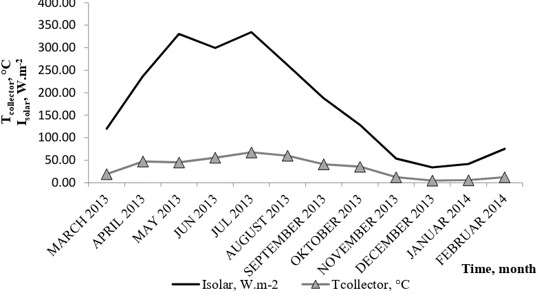
0.00 50.00 100.00 150.00 200.00 250.00 300.00 350.00 400.00
Tcolle
ct
or
,°
C
Isolar
, W
.m
-2
Time, month
Isolar, W.m-2 Tcollector, °C
very clear days, the energetic gain from solar system is lower in winter months than in the rest of the year.
It can be concluded that in winter months the amount of heat generated by solar system were decreasing by more than 20 % in comparison with summer months. Clearly with this essential information is related to a substantial increase in gas consumption for water heating. Fig. 8 show comparison of the collector’s daily temperature and average daily intensity of solar radiation for whole year divided for months. It can be concluded that the greatest intensity of solar radiation was observed during summer months as it was expected.
From our observation and according to Burch et al., 2000 costs are significantly influenced by the parameters that if the system is designed for new building or an older building (reconstruction). When applying for a new building of the solar system to remove many obstacles, i.e already during the design it is planned with the installation of solar collectors, thereby minimizing the additional indirect costs. However, 15–25 year product lifetime with high system and component reliability and performance seems to be still insufficient (Hudon et al., 2012). Solar thermal is the most cost-effective way to use the sun’s energy. For hot water intensive commercial operations, water heating can be the largest annual expense (Boone, 2015). In addition, the key drivers of the break-even cost of SWH are a combination of fuel price, local
incentives, and technical factors including the solar resource location, system size, and hot water draw (Cassard et al., 2011).
When comparing water heaters in the same location, several factors besides energy consumption need to be considered. To keep the comparison as even as possible, all water heaters should meet the same load. Some technologies, such as HPWHs and tank less water heaters, may have trouble meeting the load, because outlet temperatures sag or because of delays between water being drawn and the burner firing, respectively. Solar water heaters may provide water at a higher temperature than required because of the higher temperatures allowed in the storage tank, which will reduce the volume of hot water drawn during mixed draws. To ensure that all water heaters met the load, their energy use was normalized to account for unmet load. In actual use there would be no normalization energy, although homeowners may change their hot water use or change the set point temperature of their water heaters if they frequently experience unacceptable sag in the outlet temperature. However, including normalization energy ensures that water heaters that frequently have sag in the outlet temperature do not get an efficiency benefit from this sag. The normalization energy is defined as the additional thermal energy required meeting the load divided by the instantaneous efficiency of the water heater (Maguire et al., 2013).
CONCLUSION
The effective utilization of the solar system affects a large number of parameters. The actual orientation of the house and the location of the chimney and then placement of collectors and their tendency proved to be disadvantages and cause a great proportion of the losses. The return on investment of the solar system (whole and subsidized) is 23 years.
Considering the life of the solar system, studied system is in such engagement and the annual consumption of water (32 m3, estimated consumption of gas without a solar system 382.2 m3) not
profitable. Another disadvantage is the connection of a gas heater in the system, which in the summer months showed an excessive loss. The design allows the heater to vent out gases during its operation. During not operational time however it causes also the heat loss generated by solar system.
For these reasons, it is necessary to make certain changes on the monitoring solar system. The solution is to completely disconnect the gas heater. The output from the solar boiler is to be plugged directly in the system. Further, in the solar heaters of water an electric spiral should be activated which is a part of boiler. The spiral after plugging into the control unit shall be automatically controlled and subordinated to solar collectors. Another possibility is the involvement of the upper exchanger in a solar boiler into the central heating circuit. This would meet the needs of the hot water also through winter months and increase the effective utilisation of the whole system.
Acknowledgement
BOONE, S. 2015. Solar Energy in Canada. CanSIA. Available at: http://www.cansia.ca/sites/default/files/231. pdf
BURCH, J. CHRISTENSEN, C., SALASOVICH, J., LORARD, B., SCHOLTEN and B. JUNE 2000. Cost-Benefit Modeling of Solar Domestic Hot Water Systems. In: Proceedings of the ASES Annual Conference.
CASSARD, H., DENHOLM, P. and ONG, S. 2011. Break‑even Cost for Residential Solar Water Heating in the United States: Key Drivers and Sensitivities. Technical Report NREL/TP-6A20-48986. Golden, CO: National Renewable Energy Laboratory. Avilable at: http://www.nrel.gov/docs/fy11osti/48986.pdf [Accessed: 2016 December 23].
DENHOLM, P. 2007. The Technical Potential of Solar Water Heating to Reduce Fossil Fuel Use and Greenhouse Gas Emissions in the United States. Technical Report NREL/TP-640-41157. Golden, CO: National Renewable Energy Laboratory. Available at: www.nrel.gov/docs/fy07osti/41157.pdf [Accessed: 2016 December 23]. EIA. 2009. Residential Energy Consumption Survey 2009. Washington, D.C.: Energy Information Administration,
U.S. Department of Energy. Available at: http://www.eia.doe.gov/emeu/recs/ [Accessed: 2016 December 23].
HUDON, K. MERRIGAN, T. BURCH, J. and MAGUIRE, J. 2012. Low‑Cost Solar Water Heating Research and Development Roadmap. Technical Report NREL/TP-5500-54793. Golden, CO: National Renewable Energy Laboratory. Available at: http://www.solarthermalworld.org/sites/gstec/files/story/2015-05-24/low-cost_ solar_water_heating_research_and_development_toadmap.pdf [Accessed: 2016 December 23].
MAGUIRE, J., FANG, X. and WILSON, E. 2013. Comparison of Advanced Residential Water Heating Technologies in the United States. Technical Report NREL/TP-5500-55475. Golden, CO: National Renewable Energy Laboratory, 2013. Available at: http://apps1.eere.energy.gov/buildings/publications/ pdfs/building_america/comparison_water_heating_tech.pdf [Accessed: 2016 December 23].
MURTINGER, K. and TRUXA, J. 2010. Solar energy for your house. [in Czech: Solární energie pro váš dům]. Brno: Computer press.
Contact information Ján Jobbágy: [email protected]
Koloman Krištof: [email protected] Pavol Findura: [email protected]