44
cModeling and Production of Solid Model of South Panel, Tuncbilek Open Pit by 3D Printer
İsmet Çelik
1, Enes Zengin,
2Cem Şensöğüt
3*1 Dumlupinar University, Mechanical Engineering Department, Kutahya, Turkey 2
Dumlupinar University, Geological Engineering Department, Kutahya, Turkey
3 Dumlupinar University, Mining Engineering Department, Kutahya, Turkey
*Email: [email protected]
Received: 5 December, 2017 Accepted: 29 April, 2018 Abstract: Three-dimensional printers have begun to be widely used in machinery, architecture, construction, education, mould design, medical and dental fields to produce visual and functional parts. With this technology, manufacturing is realized jointly layer by layer, and there is no restriction in terms of part shape and detailing. Objects are scanned with optical scanning devices at first by means of reverse engineering and then converted to the computer aided design (CAD) data by making necessary arrangements on the scanning data. In this study, the CAD data of the open pit area of South Panel, Tuncbilek, Turkish Coal Board was formed by mapping and reverse engineering software of topographical points, and then colored solid modeling was formed with 3D printers.
Keywords:Solid model, 3D printing, reverse engineering, open pit mining.
Introduction
In the reverse engineering process, the scanned points of an object are transformed into a point cloud or triangular mesh patterns so that further restoration operations can be performed. All features obtained for the specific point, such as shape, texture and color, can be used in CAD environments via triangular mesh. This process is called reverse engineering (Sokol and Cekus, 2017) The point cloud obtained at the end of the scanning of the object in concern with optical scanning devices is passed through a number of arrangements to obtain the CAD data of the object. The CAD data can be used later for manufacturing.
Geomagic is powerful reverse engineering software. Minetola and his colleagues have compared six reverse engineering softwares (3D Reshaper, Geomagic, Gom Inspect, Point Master, Polyworks, Rapidform) used commonly in the world for research work. They have taken into account the interpretations, feedbacks and experimental test results of expert users in their comparative studies, and have indicated that the best grade belongs to Geomagic (Minetola et al., 2015)
In recent years, prototype products have also been used as original parts in medical, electronic and automation systems. In this case, prototyping can be preferred because it is more economical than serial production for fewer production runs. Designers use fast prototype apparatus to fabricate prototypes of 3D models in a short time. These devices produce parts by creating layers from scratch and superimposing the layers, not by lifting chips from filled material as in conventional manufacturing methods.
The layered manufacturing method used in prototype production started about 50 years ago. However, its use in the field of topography and photo-sculpture goes back to 100 years. Rapid prototyping is a common
name given to the technology of devices that produce parts from 3D CAD data, plastic or metal materials. This technology, which began to be used in the field of topography in the 1890s (Blanther, 1892), began with the stereo lithography technique and Munz proposed in 1951 (Munz, 1956). In 1968, Swainson developed a technology that works by the polymerization method obtained at the intersection of two laser beams (Swainson, 1977). Ciraud developed a 3DP (Three-Dimensional Printer) technology that worked by combining dust in 1971 (Ciraud, 1972). Another work in this area was developed by Housholder in 1981 by improving laser sintering with powder. During this work, the accumulation of planar layers in sequence (superposition) and the solidification of each layer were also examined (Householder, 1981).
At the end of the 1980s and early 1990s, layered manufacturing technologies were seen to increase in the research and implementation processes. Over the next two decades, research communities have emerged that address these processes in more technical ways. The use of 3DP technologies has continued to grow, both in terms of commercial and scientific activities. In the world, the total budget for the layered manufacturing technologies and services for 2008 is approximately $ 1.2 billion. The budget allocated for layered manufacturing technologies has increased by about 10% every year in the last five years (Wohlers, 2009).
When the literature on 3DPs is examined, it can be said that the following studies are in the forefront:
In collaboration of Department of Mechanical Engineering with Faculty of Medicine at Maribor University, in Slovenia, research and application studies were carried out on the design of implants that can be used in bone structures and production with rapid prototyping technologies (Drstvensek, 2009).
ISSN: 2223-957X Journal home page: www.econ-environ-geol.org
The first effective use of 3DP technology in Turkey was made in 2003 in cooperation with Cadem Inc. and American Hospital. In the study, optical CT data for skull and face were used for implant design, manufacturing and surgical modeling. In this study, implant was made of titanium material (Negis, 2009).
ArcGIS software is used in geological engineering mapping processes. ArcGIS software has many features, primarily mapping, modeling, and analysis, and is widely used by engineers, city planners, and people interested in statistical information. Any type of modeling can be performed using the files (.format) defining the coordinates and heights with ArcGIS, and the necessary analysis can be performed on the created model. If there are points belonging to a piece of land, these points can be mapped and the surface of the region can also be mapped.
Mapping and reverse engineering of topographical points of a mining site for the modeling and production of the field with 3DP technologies have not been adequately studied in the literature. After a comprehensive evaluation, the aim is to form a colored, three dimensional and solid model of the Southern Panel of Tunçbilek open pit.
Work Carrıed Out
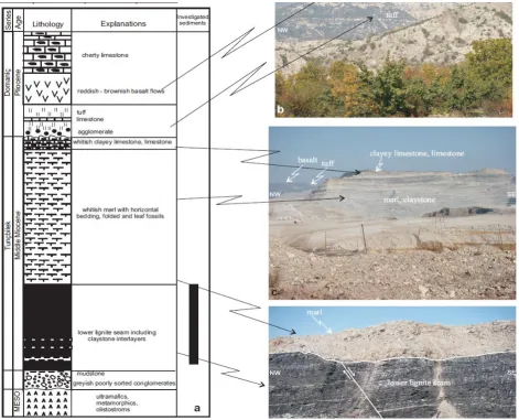
A solid modeling of one of the Tunçbilek Open Pits called Southern Panel was realized in the present work. Geological map of the study area is given in Figure 1. First of all, the topographical points of the site were taken from the Western Lignite Corporation (WLC – Turkish Coal Board) Directorate and processed through ArcGIS, geographic information systems software. The points converted to .wrl file structure in ArcGIS software are then rearranged in reverse engineering methods in Geomagic software and converted to .stl format. In the third stage, the .stl formatted file was put on satellite photo in 3DP software and the colored, three-dimensional model of the created model was produced in 3DP printer. These steps are explained below accordingly:
Converting the Topographical Points of the Site to .wrl Format with ArcGIS Program
The development of two and three dimensional analysis through computer technology has led to the emergence of software based on geographic information systems. By means of that software which is based on point coordinates, elevation models can be formed by using data obtained from geological studies.
Especially with the developing technology, the size and content of the studies that have been achieved due to the ease of providing, storing and analyzing the data have also improved. Numerical height models of very large areas can be performed via work stations with appropriate equipment. In the same way, the changes in these models can be followed in the conditions where the data transfer is provided regularly. Among such software, ArcGIS 10.4 software, which is most widely used, is utilized in the current work.
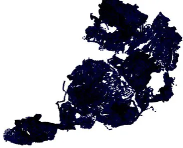
In order to create a three-dimensional digital field model of Tunçbilek Open Pit, which is determined as a study area in the scope of the present research work, elevation data with 158206 different coordinates of the region was provided (Fig. 2). In accordance with the European Datum 1950" coordinate system, topographical studies and previously defined points (coordinate and elevation data) were loaded into Microsoft Excel software. This file with the extension .xls was then transferred to ArcGIS software. The points in the .xls extension file have been defined using the tools included in the software and a file with a .shp (Shape File) extension has been created with coordinates and height data. For each point in the .shp file created by the point type, the coordinate and height data for that point are defined.
Fig. 2 Point data of study area.
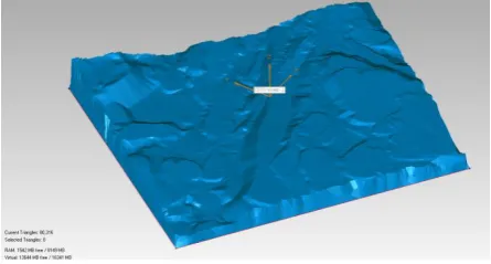
By using the data in the generated point-type .shp file, a triangular irregular networks formatted from topographical model was created to take into account all points (Fig. 3). In this model, non-natural surface models which are formed due to erroneous point data are extracted and removed from the original point data. In creating the topographical model (.tin), all the data in the .shp file are taken into account and triangle meshes are created between the points. During this formation, portions where dot data are dense allow a smoother and realistic topography modeling, while irregular topography occurs in areas where dot data are sparse. The points taken in this study are thought to be sufficient. The multiplicity of data obtained has made the numerical field model to have a very high reflectance of the actual topography. In the first step, numerical site model of the study area was formed by using the mentioned data.
Fig. 3 Topographic model of study area.
Since the whole site is very large and the Southern Panel of 6.32 km2 is taken into consideration in order to obtain better detail from the model to be produced (Figs. 4, 5).
Direct conversion from ArcGIS to .stl format used by 3-Dimensional Printers (3DP) during printing is not possible. However, conversion to .wrl (Virtual Reality Modeling language) format, which ArcGIS reverse engineering software can take as data entry, can be realized. For this purpose, the data of the modeled part is converted into .wrl format and processed by reverse engineering software.
Creating .stl Model of the Site with Geomagic Reverse Engineering Software
With ArcGIS software, the file converted into .stl is not in a state that can be generated by 3DP. This is due to the reason that the created model is a surface model with no thickness. There are unsuitable intersections, pointed spots, wrinkles, and undefined small areas. In addition, there is no bottom surface (platform) for production to be achieved, and the boundaries are not suitable for manufacturing. In this phase, the file created in .wrl format with ArcGIS software in Geological Engineering Department of Dumlupinar University was converted into .stl file format which can be processed by Geomagic reverse engineering software by Mechanical Engineering Department of Dumlupinar University and can be produced with 3D Printer.
Fig. 4 Boundaries and Points defining the boundaries of
selected study area.
The .stl (stereo lithography) files are a file structure that defines the surface geometry of the object using triangular polygons (Fig. 6-c). .stl, a widely accepted data standard in the 3DP industry, is the display scheme of object models based on triangles or quadrangles (Matta et al., 2015). The points of an object are knitted in the form of triangle-forming nets. This is also called triangular mesh structure. The structure belonging to the entire object symbolized by each triangle, three points and a direction vector is represented in this file. A file in .stl format is regarded as direct data entry by the software of the 3DP devices, and the component construction is performed accordingly (Çelik et al., 2013).
The inappropriate intersections, spikes, wrinkles, small undefined regions as shown in Figures 6a, 6b were worked on and corrected by Geomagic reverse engineering software (Figs. 6a, b). At the last stage, the base and border of the model were created. For this, an XY plane perpendicular to the Z axis is defined and this plane is provided as the base of the model. The model was created by lowering the boundaries of the proposed planar model vertically and the base XY plane of the model was closed in a plane (Fig. 7). The entire process, without the automatic correction command, has been performed manually so that the original coordinates remain unchanged. The created model was saved in .stl file format.
Fig. 6 (a) wrl file obtained from ArcGIS software, (b)
intersections, spikes, wrinkles, small undefined regions at the
surface, (c) .stl polygon file corrected by Geomagic software.
Fig. 7Converted and base level formed model.
Accommodating the Aerial Photo on the Model and Production with Colored 3DP
The model of .stl taken in the 3DP program is now a closed-volume solid model and has topological three-dimensional forms (Fig. 8). At this stage of the work, firstly, the aim is to make the aerial photograph on the model and produce a more realistic model. The current satellite photos of the zone have been obtained both from WLC and from Google Earth Pro software so that the surface of the physical model to be produced using 3DP can be put on the surface.
Fig. 8Topographic solid model of selected study area.
Satellite photographs, which cover the limits of the digital elevation model, are based on the current model. By the assistance of the Z-Edit program of the 3DP, the aerial photograph of the site is placed on the model. The most important point here is the exact overlap of the model with the photograph to be put on the model. These limits are clearly set and photographed on the model (Fig. 9). The generated Z-Edit file is a file ready for production on the ZP 250 brand 3DP printer. As a result, the field was separated into slices in the Z-Edit program of the ZP250 device and the production was performed layer by layer.
Fig. 9 Topographic solid model design of selected study area with the photograph.
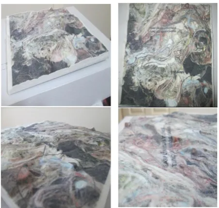
Fig. 10 Colored solid model produced in the 3D printer of the mine site.
Usability of Model in Mine Operations
It is possible to benefit from the information technology and field prototypes at every stage of the open-pit mining. As explained in the sections 2.1, 2.2 and 2.3, a three-dimensional model of a mine site can be made in color, using reverse engineering and three-dimensional printers. The facilities that can be achieved in the open pit mining operation by using the 3 dimensional models are summarized as follows.
- In carrying out the preliminary analysis necessary for the determination of the licensed sites.
- Determination of altitudes and slopes belonging to the site to be excavated in order to determine and slide susceptibility and hydrological risk analysis.
- In the preparation of annual mining production maps, preparation of production panels and volume-reserve calculations for the production area.
- In the realization of block modeling and geostatistical estimations with the evaluation of drilling data related to the projected site.
- Bench and ramp designs for open pit operation, formation of open pit surfaces, blasting design suitable for determined rock characteristics.
- The most suitable horizontal and vertical platform parameter values for the connection between the pit and the overburden piling zone.
- It can be used in environmental impact assessment analysis within the scope of rehabilitation activities that can be applied after mine closure.
Discussion and Conclusion
In this work, solid and color modeling of an open pit site has been successfully accomplished by using the latest design and manufacturing technologies and software, mapping, reverse engineering and 3D printers. The actual model of a real site could also be produced with 3DP by placing photographs on the model. In this study, mapping of topographic real points of a mine site with ArcGIS software was carried out with the help of discipline of geological engineering. In addition, by the assistance of discipline of mechanical engineering, these data were converted into production ready data by means of 3D printer and production. Finally, evaluation of this field model produced with three dimensions was completed by mining engineering discipline. The work is new and important in terms of interdisciplinary and use of new technologies. The resulting model provided excellent visuals. With this preliminary work, the mine operators will have extraordinary ease of planning the preparation and production at each stage of open field operation.
It is important to clearly define the boundaries of the site to be modeled during operation. In the same way, it must be exactly in line with the boundaries defined in the photograph. Otherwise there may be differences between the photo and the model.
The study can also be applied in the modeling of the underground mine roadways, in the colored and solid modeling of settlements, dams and strategically significant areas on the earth. These and similar studies can be used in modeling roads, dams, parks, cities and even military sites with field models.
References
Akkiraz, S. M., Akgun, F., Utescher, T., Wilde, V., Bruch, A. A., Mosbrugger, V., Ucbas, D. S. (2012). Palaeoflora and climate of lignite-bearing Lower−Middle Miocene sediments in the Seyitömer and Tunçbilek Sub-basins, Kütahya Province, Northwest Turkey”, Turkish Journal of Earth Sciences, 21, 213-235
Blanther, J. E. (1892). Manufacture of contour relief maps. U.S. Patent, # 473, 901.
Çelik, İ., Karakoç, F., Çakır, M. C., Duysak, A. (2013). Hızlı prototipleme teknolojileri ve uygulama alanları. DPÜ Fen Bilimleri Enstitüsü Dergisi. 31, 53-69.
Ciraud, P. A. (1972). Process and device for the manufacture of any objects desired from any meltable material, FRG Disclosure Publication.
US-TURKEY Workshop on Rapid Technologies, September 24, 75-81,
Housholder, R. F. (1981). Molding Process. U. S. Patent #4, 247,508.
Matta, A. K., Raju, D. R., Suman K. R. S. (2015). The integration of CAD/CAM and rapid prototyping in roduct development: A review. Materials Today: Proceedings,2, 3438 – 3445
Minetola, P., luliano, L., Calignano, F. (2015). A customer oriented methodology for reverse engineering software selection in the computer aided inspection scenario. Computers in Industry. 67, 54–71
Munz, O. J. (1956). Photo-Glyph recording. US Patent, #2,775,758.
Negis, E. (2009). A short history and applications of 3D printing technologies in Turkey, US-TURKEY Workshop on Rapid Technologies, September 24, 23-30.
Sokol, K.., Cekus, D. (2017). Reverse Engineering as a solution in Parts process” Procedia Engineering, 177, 210-217.
Swainson, W. K. (1977). Method, medium and apparatus for producing three-dimensional figure product. U.S. Patent # 4.041.476.