EAI Endorsed Transactions
on Energy Web and Information Technologies
Research Article
Justifying and choosing parameters of the wind
power installation with an automatically controlled
sailing working body
K.S. Sholanov
1, B I. Mirzabaev
1, K.A. Abzhaparov
2,*1
Karaganda state technical university, Karaganda, Kazakhstan; [email protected] 2Satbayev University, Republic of Kazakhstan, [email protected]
Abstract
The article considers a wind power installation, which significantly differs from the other existing wind power installations in that it has rocking an automatically controlled sail of a toroidal shape and a manipulator converter of the wind kinetic energy to the mechanical energy of forward motion. Having analyzed aerodynamic variables, timing chart, and having built a simplified dynamic model, the authors determined geometric, kinematic and dynamic properties, which are necessary for the future design engineering, automatic control and research of the wind power installation. The study gives a description of the acting laboratory-scale model of the sail wind power installation and performance test results.
Keywords: wind power installation, working body, controlled sail, manipulator converter.
Received on 01 May 2018, accepted on 13 September 2018,published on 25 October 2018
Copyright © 2018 K.S. Sholanovet al., licensed to EAI. This is an open access article distributed under the terms of the Creative Commons Attribution licence (http://creativecommons.org/licenses/by/3.0/), which permits unlimited use, distribution and reproduction in any medium so long as the original work is properly cited.
doi: 10.4108/eai.12-9-2018.155860
1. Introduction
Currently, the direction associated with the use of wind energy is intensively developing in renewable energy. The turbine wind power installations (WPI) used in this process are divided into wind power installation with horizontal and vertical orientation of the turbine axis [1]. Moreover, most found the use of wind power installation with a horizontal axis orientation of the turbine, the rotor blades of these turbines are moving under the action of the lifting forces of the wind [2]. In this case, the coefficient of wind energy use does not exceed the Beta coefficient equal to 0.593. Independent of changes in wind direction, the operation is distinguished by turbine wind power installation with a vertical orientation of the turbine axis. In these wind power installation the turbine work due to the forces of resistance to the air flow [3].
However, the main problem of turbine wind power installation of both types is the unpredictability of wind, speed and strength of wind gusts, often changing in short
periods of time. In addition, the lower limit of the range of wind speeds at which power output of the turbine wind power installation is usually 30% of the nominal is approximately equal to 8 m/s while areas with a range of wind speeds from 3M/s in most occupy a vast territory with a population and industrial capacity. It is in these areas that the use of turbine wind power installation is not effective enough.
To increase the utilization of wind energy, instead of rotating turbine blades, sailing wind power installation are offered, for example, with a rectangular sail design and a vertical rotation shaft [4]. This design is similar to a WPI with a vertical axis of the turbine. Another sailing WPI has a fundamental difference in that it does not have a rotating turbine [5]. However, in this windmill all the driving devices that support the work of the windmill are located on the mast. This creates undesirable dynamic loads that cause mast swings and additional loads on the devices and in their connections.
However, in this WPI all driving devices that provide WPI operation are located on the mast. This creates an
*
undesirable dynamic loads, causing vibrations of the mast and the additional load on the devices and their connections. In order to improve the efficiency of wind power installation, the article proposes a new sailing WPI [6], in which the working body is a toroidal sail, swinging under the action of the lifting force and the wind resistance force. The peculiarity of the WPI design is that the movements of the swinging sail are transmitted to the moving platform of the parallel manipulator, which converts these movements into six translational movements. In the future, the energy of translational movements by known methods, for example, through mechanical, pneumatic, hydraulic devices are converted into electrical energy. Thus, the efficiency of wind power installation is increased, on the other hand, all massive moving devices are located on a fixed base, increasing the reliability and durability of wind power installation.
2. Design and operation mode of the WPI
In the new WPI sail, toroidal shape has an aerodynamic profile in the cross sections and can be executed in the form of a hollow body of dense elastic material (parachute fabric) filled with gas or can be made of lightweight synthetic or composite material. For example, in Fig.1 a, the sail made of foam is presented. Depending on the wind speed, the volume of the hollow sail changes by injection or bleed gas or in other ways to change the windage. The presence of such a sail allows the WPI to start functioning at a wind speed of 1.5-2 m/s. Under the action of the wind, the sail makes spatial periodic movements depending on the direction and speed of the wind.
In the WPI, the sail is located at an altitude of more than 10 m and is rigidly connected to the upper platform of the parallel six-movable manipulator (Fig.1,b) created earlier platform robot SHOLKOR [7]. This manipulator allows you to transform the spatial movements of the sail into a series of translational movements. Figure 1, b shows the physical model of the sholkor robot parallel manipulator. Here the lower platform 1 is connected to the upper platform 2 by means of six actuators 3. The feature of the model is that for the connection of actuators with platforms applied a flexible connections protected by a patent [6,8], allowing to exploit the complex connections without grease in the open air and the aquatic environment.
a) b)
Figure 1. Device model of WPI
а) the sail, б) parallel manipulator
Figure 2 shows the scheme of wind power installation, used in the future as a calculation. Here, sail 13 is connected by three spacer rods 12 to the upper platform of the manipulator. This design forms the working body of the WPI. The working body together with the manipulator is further called the manipulator сonverter (MС). The movable platform 2 of the manipulator is connected to the lower fixed platform 1 by means of six actuators (rod-cylinder) 3-8. Each actuator represents the connection of piston 9 and cylinder 10. A flexible connection 11 connects the actuators with the manipulator platforms and among themselves.
Here, in the WPI the sail captures the kinetic energy of the air mass, and the manipulator converts this energy into mechanical energy of the forward motion of six rods relative to the cylinders.
The novelty of the present sail WPI is the presence of an airfoil section sail with an automatically controlled aerodynamic surface area. This assumes automatic control of the WPI operation as a whole.
In this regard, the aim is to justify the functionality of sailing wind power installation. To do this, the justification for choosing the shape of the dimensions and the sail is performed sequentially. Then we consider a simplified dynamic model of the working body (hereinafter WB), which allows to correctly solve the problem of dynamic analysis of the working body and MС WPI for the subsequent solution of problems of calculation of the design of the WPI as a whole and the design of the automatic control system.
19
1 A
4
5 B
8
3
7 2
6 C
C
B
A
9
10
1
2
2
2
1
1
O
X
Y
1 1
O
1 1
1o
R
F
F
O
1
2
r
O
1
S
Z
r C
k
d
O
r1A
Mw
F
0 2Q
13
12
G
Justifying and choosing parameters of the wind power installation with an automatically controlled sailing working body
3. Justifying the choice of the sail shape
and size
Trivial task for any WPI is to capture as much of the kinetic energy of the air mass as possible and convert this energy to electric energy with minimal losses. In order to effectively perceive the kinetic energy of the air mass, the working body of the WPI must be sensitive to changes in the magnitude and direction of the airflow speed and force. These requirements are fully met by the proposed sail. Firstly, the sail placed on the vertical spacers connected with the upper platform of the MC have a circular symmetric shape in order to perceive any lateral wind directions. Such bodies can be forms of balloons, planning parachutes, and airplanes. However, this article proposes a toroidal-shaped sail with an aerofoil section.
Aerodynamic analysis of the performance of a toroidal sail with an aerofoil section (Figure 2) shows that the lateral airflow causes distributed dynamic loads, the resultant of which at the angle of attack α will be the drag forces F2 and lifting force F1, located in the plane of motion.
The choice of an appropriate aerofoil section allows to obtain high values of the slip factor
2 1
F
F
.The resultant lifting force and drag force for bodies with an aerofoil section are determined by the dependences [2]
2 1
2
1
W P
A
S
v
c
F
,2 2
2
1
W P
W
S
v
c
F
. (1)Here
c
A,
c
W,
S
P,
v
Wdenote the experimentallydetermined coefficient of lifting force and the drag force respectively, as well as air density, the surface of area blown by the wind, and the average wind speed.
The choice of the toroidal shape of the sail is explained by the fact that the sail under an action of a wind gust with vW speed moves approximately to the direction of the force R. At a certain inclination of the sail, the airflow breaks off from the sail surface and passes through the torus opening. In this case, the effect of the action of the wind force decreases and the sail returns to its original position due to elastic forces in the actuators MC. Thus, the sail swings near the vertical position in the plane of action of aerodynamic forces.
The initial value for determining the sail dimensions is the required power of the WPI (N), the estimated value of the WPI efficiency (), and also the average wind speed in the area of use of the turbine (vW). The air mass capacity will be determined by the expression
3
2
1
W
W
S
v
N
, (2)where NW =N/.
From expression (2) we determine the area of the frontal surface by which the sail dimensions will be determined
3
2
W
v
N
S
.Using the movement inversion method to the horizontal component of the aerodynamic force, we rotate clockwise the vector F2 around the axis passing through the center of the torus perpendicular to the plane Q force actions F1 and F2. The extreme position of the F20 force line passing tangentially to the lower edge of the torus corresponds to the case when the wind flow begins to pass through the torus opening. In this case, the aerodynamic effect is sharply reduced due to the flow breakdown. The angle M between the lines of action of forces F2 and F20 can be determined from the dimensions of the torus and the aerodynamic cross section
2(
)
P M
h
arctg
r
s
,where hР is the profile thickness;
Figure2 shows that Сk =hР/2; r is the inner radius of the torus; s=kd is the coordinate of the most distant point of the torus.
The angle of the vertical axis deflection
O
10O
r1fromthe initial position
O
10O
ris equal to the deflection angle M of the action line of the forces F2 in the reversed motion and corresponds to the maximum amplitude АW of the WB rolling.4. Dynamic analysis of the working body
When solving problems of dynamic analysis and subsequent synthesis of the control system, we keepin mind that that the energy source is the kinetic energy of the wind; the system is nonlinear because the wind effective force is proportional to the square of the speed; external action represents a pulsating load. The pulsating load consists of two components: the first is a quasi-static one formed of the low-frequency component of the wind gust; the second one represents the resonant frequency. In the calculations below, the most common low-frequency component is used. The resonant component is not considered since the automatic control system will prevent the resonance effect. The frequency of wind pulsation is taken from the results of experiments as the most characteristic for strong winds [9].
The task of dynamic analysis and subsequent synthesis of the control system is to choose the geometric, kinematic and power characteristics of the WPI. In the synthesis of the automatic control system of the sail and the WPI as a whole, the law of mass variation or sail surface area variation (when controlled) is determined that would ensure stable self-oscillation of the WB with different amplitudes depending on the disturbing effect of the wind and the input signals of the control system. It is known that natural oscillations of the system (self-oscillations) arise in cases when the conjugate roots of the characteristic equation are imaginary.
Compliance of the roots with these conditions and stability of periodic solutions can be achieved by choosing the variable parameters of the system, for example, the sail surface area, shape of the section, and dimensions. This confirms real possibility of creating a controlled WPI with stable auto-oscillations processes.
When building a simplified dynamic model of the working body, we take the sail for a solid body that performs a flat motion in the plane Q. It is also assumed that the motion of the working body occurs in the plane Q (Fig.2) the action of the resultant forces from the wind pressure passing through the axis of rotation of the torus. In the initial position, the axis of rotation of the torus is perpendicular to the surface of the Earth (always perpendicular to the lower platform of the manipulator). The working body is considered as a body clamped to a fixed platform 2. All the external forces, reaction forces RY, RZ and the reaction moment MR is located in the plane Q, form a flat system of forces and cause a planar movement of the working body in the plane Q. it is Important to note that the movement of the working body to represent periodic motion in the plane Q. the position of the movable in the General plane Q depends on the direction of the wind speed.
The calculation is based on the external load corresponding to the highest wind speed. In the case where the wind speed exceeds 20 m / s, the sail is folded, for example, by venting gas to prevent the destruction of wind power installation.
We choose the fixed coordinate system О01X0Y0Zo associated with the MC's fixed platform (Figure 2) and the moving coordinate system O1X1Y1Z1 with the origin on
the moving platform and the axis O1Z1 coinciding with the sail’s axis of symmetry and the axis O0
1Z0 in the initial position. The plane O1Y1Z1 coincides with the plane Q.
Dynamics of the WB is described by a system of three nonlinear second-order equations:
2 2
2
)
(
2
1
dt
dy
v
S
c
dt
y
d
M
sW P W
s
, (3)
y s
W P A
s
R
G
dt
dz
v
S
c
t
d
z
d
M
2
2
2
)
(
2
1
(4)
R OY
mom
F
F
M
J
(
1.
2)
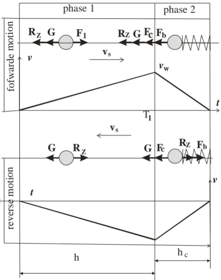
. (5) Here, M is the mass of the WB, ys,zs, are the coordinates of the center of mass in the fixed coordinate system and the angle of rotation with respect to the axis passing through S perpendicular to the plane O0Y0Z0.We should note that the right-hand side of equations (3-5) varies depending on the operation mode of the WPI. In this regard, we will make a cyclogram of movement (Fig.3) and highlight the following modes of operation: forward motion of the sail under the action of wind force, and the reverse motion mode under the action of elastic forces accumulated in the elements of the MC’s telescopic joints. The forward motion mode is in turn divided into 2 stages. In the first stage, the sail moves uniformly accelerated, advancing by the value of the maximum motion h corresponding to the maximum amplitude AW or the position when the sail acquires a speed equal to the wind speed. When the sail reaches the wind speed, then the effect of aerodynamic forces of the wind not consider. At the second stage, the wind forces do not act, the sail accumulates the energy of elastic forces and moves equally retarded. Due to this, at the end of the second stage the sail speed is zero. The reverse motion is performed at the first stage, uniformly accelerated, with the energy recuperation in the elastic elements of the MC actuators. At the second stage of the reverse motion, due to the initial speed obtained at the end of the first stage and due to external forces, the motion is uniformly accelerated. At the end of the second stage of the reverse motion, the sail speed is zero. In the reverse motion, the effect of wind forces is neglected since it is believed that there are no gusts of wind in this time zone due to the cyclical nature of its impact.
R G F
R G 1 F Fc b
v vw t T1 R G R
G Fc Fb
t
v vs
vs
h hc
phase 1 phase 2
fo fw a rd e m o ti o n re v er se m o ti o n Z Z Z Z
Figure 3. Timing chart of the relocation of the center
of mass S relative to the axis O01Z
Let us consider a forward motion mode. Due to the properties of the aerodynamic profile of the sail, the lifting aerodynamic force F1 is much higher than the force F2. This mode is the first to consider because it is crucial for further establishing the working motion of the rod and displacement of the rod under the action of elastic forces. In the analysis of the forward motion mode, in this case the limitation is the motion time which depends on the frequency of the wind pulsation H [9]. Therefore, the forward motion time in the first stage is T1=H/2 c. The component of the acceleration at the beginning of the first
stage is
a
Y
v
W/
T
1. We determine working motioncorresponding to the maximum motion:
2
/
2 1T
a
h
W
.Equation (4) is nonlinear, so we will seek an approximate solution in increments of speed and time. For this, we split the action time of wind force into n, equal intervals of time, then produce quantization at the time
n
/
T
t
1
We assume that an impulse of force depending on the squared speed acts on the center of mass in a finite interval of time. The speed of the sail on each segment of time decreases by the value of the sum of the speed change on the previous segments. This is due to the fact that the expression for the lifting force has a wind speed relative to the sail. At each i-th interval, a lifting force decreasing in magnitude acts on the sail because the relative wind speed decreases. Equation (4) can be represented in the form of a system of equationst R G v v A M
v iZs iZ
i
W s
Z
1 [ (
)2 ]1
1
1 ,i=1,,.n. (6)
Here А1= A
S
P2
1
c
, constant;Expression (6) allows us to determine the vertical component of the speed of the WB's center of mass and of the sail at any time in the first stage of forward motion.
Since at the initial moment
v
0s
0
, then from (6) weobtain the dependence for the vertical component of the reaction force and its maximum value RnZ.
At the second stage of the forward motion during the movement of the center of mass S, elastic forces
c
F
c
(zs-h) and damping forcesdt
dz
b
F
b
sactuators, as well as gravitational forces that impede the motion, act in the direction of the y axis, so the dynamics equation (4) will have the form
0
)
(
2 2
s s nZs
c
z
h
G
R
dt
dz
b
t
d
z
d
M
, (7) where b, c are damping and elastic coefficients; RnZ is the reaction composite force determined from (6) at i=n.
By solving the differential equation (7), given M, b, h, G, RnZ and initial speed vW, we determine T2, motion time at this stage, and c, an elastic coefficient of the damping elements. Assuming that the law of motion is uniformly retarded, we determine hC movement in the area of stage 2, at which the energy of the elastic elements accumulates.
At the first stage of the reverse motion, the energy of elastic elements is recuperated. The equation of the dynamics of S motion relative to axis O0Z0 at this stage is as follows:
0
)
(
2 2
s c s Zs
c
h
z
G
R
dt
dz
b
t
d
z
d
M
(8)By solving the differential equation (8), the reaction forces and acceleration at this stage are determined. Given a uniformly accelerated motion, the final speed at the stage v3 and the reaction force are determined. At the second stage of the reverse motion, motion occurs only under the action of gravity and the reaction force. The speed at this stage changes from the initial value v0 = v3 to zero, and the distance traveled by the center of mass is known and equal to h.
0
2 2
Zs
G
R
t
d
z
d
M
(9)
Solving the inhomogeneous differential equation (7) enables to establish the dependence of the motion of the center of mass in the second stage of the forward motion and the elastic coefficient. In future calculations, the value of the elastic coefficient will be checked. From the
operating conditions of the WPI it follows that in the second stage of the forward motion, the energy of the elastic forces actuators is accumulated which makes it possible to return the working body to the initial position during the reverse motion. In this connection, the elastic coefficient must meet these requirements. In case of noncompliance of the elastic coefficient, the calculation cycle is repeated.
From equation (9) we determine the acceleration. Then, assuming that the motion is uniformly retarded, we determine the v0 value, the time of the second stage of the
reverse motion T2 and the reaction force
R
Z.From then on, when building a simplified model and making a dynamic analysis of the center of mass relocation with respect to the axis O01Y0 (3) and rotation around the axis passing through the point S perpendicular to the plane Q (5), the solutions and arguments given in the analysis of the center of mass motion relative to the axis O01Z0 are repeated. As a result, we determine the maximum values of the composite force of reaction RY and moment of couple MR. The moment and forces of a reaction acting on the working body from a conditionally "rigidly fixed" platform are the initial ones for force analysis of the MC.
5. Dynamic analysis of the manipulator
converter
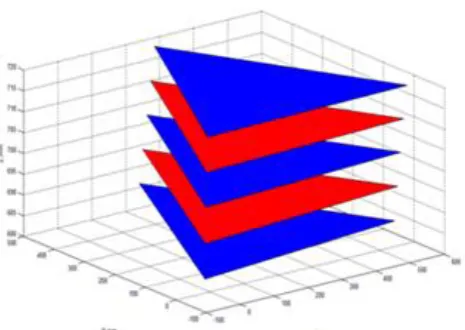
If we take into account that the sail is influenced by a resultant of aerodynamic forces of wind and gravitational force of the working body, then during cyclic variation of the wind speed and the change of the wind direction, the working body's movement will be spatially closed. With this movement of the upper platform, the lengths of all six telescopic joints will vary. Shown in Figure 4, results of solving a kinematic task for a parallel manipulator in MatLab by the algorithm proposed in [10] demonstrate that during the reverse motion of the movable platform all six rods receive the displacement increment.
To estimate the power of the WPI during the engineering or in operation, data are required on the forces in actuators and the rods motion speed. Force of the cylinder rod along with the motion allow to choose the design of pneumatic and hydraulic cylinders. To determine the forces on the rods, a force analysis of the MC is performed using the kinetostatics method.
Figure 4. The diagram of location of the working
body's upper platform
The initial data is the main vector of the reaction force
Y Z
R
R
R
applied at the point O1 and a vector of a couple of forcesM
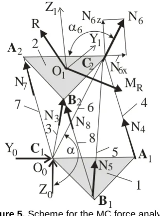
Rresulting from the dynamic analysisof the working body under the action of maximum wind speed of 15-20 m/s and with the inertia forces taken into account. It should be noted that the force
R
is located (Figure 5) in the plane Q, and the moment of coupleR
M
is directed perpendicularly to the plane Q which coincides with the moving plane O1Y1Z1. Thus, with agiven wind direction, the values
R
andM
R areknown. In addition to these forces, the unknown forces N3, N4, N5, N6, N7, N8directed along the rods' axes have an effect on platform 2. The directions of the action lines for each position are determined by solving an inverse problem of kinematics.
We choose a fixed coordinate system O0 X0Y0Z0 connected with the lower platform of the manipulator converter with the beginning in the node С1. Since
R
andR
M
comprise the inertia forces the kinetostatics equation for the platform has the following form
83
;
0
i
i
z iz
R
N
8
3
;
0
i
i
y iy
R
N
83
;
0
i
i ix
N
(
)
0
;
83
Rx
i
i
i
x
M
M
N
;
0
)
(
83
Ry i
i
i
y
M
M
N
83
.
0
)
(
i
i
i z
A
C
B
A
C
B
Z
N
N
N
N
N
N
N
N
7
1
2
3
4
5
6
8
a
a
4
5 6
7
8
x
1 1
1 2
2
2
6
6 6
3
z
Z
Y
1 1O
1Y
O
0 0 0
R
M
RFigure 5.Scheme for the MC force analysis
The obtained values of forces on the MC rod are used later in choosing pneumatic-hydraulic cylinders for the WPI design engineering.
6. A Laboratory-Scale Model of the WPI
To confirm the functional capabilities of the sail WPI and study the sail motion, an acting laboratory-scale model of the WPI has been constructed. The model is shown in Figure 6. Here, the toroidal sail 5 is fixed rigidly to the movable platform 4 of the manipulator converter. Each rod of the "rod-cylinder" connection 2 is connected to the rotor of linear electric generator 3 generating an electric current which is recorded by the micro ammeter unit 6. In the model, the sail was located at a low altitude, in addition, the sail had no aerodynamic profile in cross section and did not change the windage. Nevertheless, this model allowed to demonstrate the principle of functioning of the WPI. Namely, under the influence of the wind force, the sail made spatial movements, depending on the direction and speed of the wind. By doing it, the sail captures the kinetic energy of the air mass, whereas the manipulator converter converts this energy into mechanical energy of the forward motions of six rods relative to the cylinders, which allows to generate electrical energy.
Figure 6. An acting laboratory-scale model of the
WPI
It was possible to observe on the model that the sail, moving under the wind force action, simultaneously compresses the spring in the rod-cylinder connection. In the reverse motion, the sail was moved by the spring action. The acting model also showed that the toroidal shape of the sail prevents destructive effect of wind on the working bogy. For example, in high winds the working body was deflected by a maximum angle at which the airflow separation from the sail occurred due to toroidal shape. After the gust of wind stopped, the working body returned to its initial position under the action of elastic forces. At a given wind direction 2-3 telescopic joints were actively functioning. When the wind direction changed, there were other 2-3 telescopic joints. The movement of the working body in the absence of strong gusts of wind was represented by vibrations with a small amplitude. The essential difference between the prototype and the other existing wind power installation is the use of a swinging sail with an automatically controlled windage and a manipulator converter with six degrees of freedom.
7. Conclusion
The article analyzes the aerodynamic variables, timing chart and a built simplified dynamic model of a novel WPI. The study provided a rationale for the methods for determining the geometric dimensions and shape of the sail. The authors determined geometric, kinematic and dynamic properties which are necessary for the future design engineering, as well as for automatic control and research of the wind power installation. It is substantiated that the WPI's working body will perform self-excited vibrations in large. The study gives a description of the acting laboratory-scale model of the WPI.
References
[1] P’yankov K. S., Toporkov M. N. (2014) Mathematical modeling of flows in wind power installation with a vertical axis//Fluid Dynamics, Т. 49. № 2. pp. 249-258.
[2] Gasch. R., Twele. J. (2016) Windkraft Langer Grundlagen, Entwurf, Planung und Betrieb/ Springer, XXIII, p. 599.
[3] Apelfröjd S., Eriksson S., Bernhoff H. (2016) A Review of Research on Large Scale Modern Vertical Axis Wind power installation at Uppsala University//Energies, Т. 9. № 7. P. 570.
[4] US20140341736A1, (2014) Sail WPI. Nov. 20.
[5] US 2013 0181458A1, (2013) System for converting wind energy. Jul.18.
[6] K.S. Sholanov. Platform robot manipulator. WO/2015/016692,05.02.2015.
[7] K.S. Sholanov. Power plants (variants) on the basis of parallel manipulator. WO/2018/147716, 16.08.2018.
[8] K Tochmetova, K.S. Sholanov. Float converter model for wave power sources. Research Article in EAI Endorsed Transactions on Energy Web 17(13): e2 http://eudl.eu/issue/ew/4/13 (S 0119).
[9] M.A. Novitskii, L.M. Khachaturova, L.K. Kulizhnikova, M.K. Matskevich, (2007) Maximum fluctuations of wind direction in limited time intervals at the levels up to 300 m from observations at a meteorological tower. Russian Meteorology and Hydrology. Т. 32. № 3. pp. 168-175.