R E S E A R C H A R T I C L E
Open Access
Self-localization method for mobile robot
using acoustic beacons
Satoki Ogiso
1, Takuji Kawagishi
2, Koichi Mizutani
3*, Naoto Wakatsuki
3and Keiichi Zempo
3Abstract
In this paper, we have proposed a low-cost self-localization method which uses 4 elements of microphones, wheel rotation and sound sources as beacons, whose absolute location and frequency bands are known. The proposed method consists of following 4 steps. The proposed method (i) execute self-localization using wheel-based odometry, (ii) estimate direction-of-arrival (DOA) of the sound sources using sounds recorded by the elements of the
microphone array, (iii) predict the DOA of the sound sources from estimated location and pose, and (iv) conduct self-localization by integrating all of the information. To evaluate the proposed method, experiments were conducted. The proposed method was compared to the conventional methods, which were wheel-based odometry and
self-localization using only DOA. In the experiments, we have supposed the house-cleaning robot and its trajectory. As results, without any obstacles or walls, the mean of the estimation errors by wheel-based odometry were 670 mm and 0.08 rad, and those of self-localization using only DOA were 2870 m and 0.07 rad in the worst case. In contrast with these methods, proposed method results in 69 mm, 0.02 rad as the worst estimation error of self location and pose. From the result with occlusion of a sound source, the mean of the localization error increased 60 mm, as the proposed method detects the incorrect DOA and prevents it from estimation. From the result with reflective wave from wall, there was a place where the localization error was large. The cause of this error was considered as directivity of sound source. These results indicate that the proposed method is feasible under indoor environment.
Keywords: Self-localization; Mobile robot; Acoustic beacons; Microphone array
Background
Mobile robots are widely used indoor for building secu-rity, cleaning, automatic guided vehicle system and so on. For autonomous robots, self-localization is one of the essential function to achieve tasks autonomously. While there are needs for inexpensive robots without pre-cise self-localization, they are generally expensive because of the excessively accurate sensing. To make indoor autonomous robots inexpensive, it is essential to develop the self-localization method which does not require expensive sensor or processor and have just enough accu-racy. Conventional self-localization methods are divided mainly into two approaches: the methods which use inter-nal information and the methods which use exterinter-nal infor-mation of the robot. Internal inforinfor-mation of the robot is measured by internal sensors such as rotary encoders
*Correspondence: [email protected]
3Faculty of Engineering, Information and Systems, University of Tsukuba, Ibaraki, JP
Full list of author information is available at the end of the article
or accelerometers equipped on the robot [1]. The self-localization using these internal sensors requires rela-tively low-calculation cost, as the self-localization using these sensors are merely the accumulation of the infor-mation, such as wheel rotation obtained from rotary encoders or accelerations measured by accelerometer. Moreover, the internal sensors and the processor used for self-localization are generally inexpensive. However, once the error, such as bias of the measurement or slip of the robot, was accumulated, it cannot be detected and the estimation error piles up. Sometimes the error would be fatal as the robot cannot reach to the desti-nation or crashes into a facility. While internal sensors are low-cost, external information are usually measured by laser range finder [2], camera [3], ultrasonic range sensor [4] and microphones [5]. With the external infor-mation from laser range finder or camera, simultane-ous localization and mapping (SLAM) algorithm provides robust self-localization results as it integrates the external
information of the robot [6]. However, these sensors are generally expensive and there are much more informa-tion to be processed than the internal sensors so that it is hard to be implemented on a low-cost processors, such as microcontrollers. Even if the sensor itself was inexpen-sive, the extraction of the feature from the obtained data such as image is costly calculation or otherwise the local-ization need to be achieved by monte-carlo method which requires much memory and calculation cost than sim-ple Kalman filtering [7]. Because of these reasons, most of the self-localization methods with external informa-tion require high investment for sensors and computers. However, suitable self-localization method which does not require expensive sensor or processor and does not accumulate the error over time have not been realized.
From the reasons of the sensor cost, there are some researches focused on the sound signals as beacons to self-locate the mobile robot. Previously, many researches have been done for the use of sound signals for robots and several techniques such as the self-localization, sound sources separation and autonomous speech recogni-tion are reported [8–13]. Also there are self-localizarecogni-tion methods using microphones installed around the room [14–17]. However, most of them use a huge amount of microphones for self-localization or separation of sound signals to improve accuracy or to suppress the effect of reflective sounds. While these techniques use many microphones, it is difficult to achieve self-localization with only a few number of microphones [5]. We have proposed a self-localization method using only a few number of microphones and conducted simulation to examine it [18, 19]. This is based on the techniques using microphone array consists of small element number [20–22].
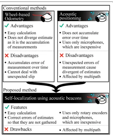
In this paper, we propose a low-cost self-localization method which uses 4 elements of microphones, wheel rotation and known sound sources as beacons. Compar-ison of conventional low-cost self-localization methods and proposed method is shown in Fig. 1. Wheel-based odometry is one of the most popular self-localization methods, as it is easy to be implemented. However, it is known that the errors of measurements are accumu-lated and the total estimation error increase over time. In contrast, acoustic localization method does not accumu-late errors of measurements, while the estimation results of this method sometimes diverge. The proposed method is the combination of these two. The features of the proposed method are followings:
• The proposed method uses only low cost sensors: a few microphones and rotary encoders.
• The proposed method combines 2 low-cost methods, which have complementary properties, to improve accuracy of each other.
Fig. 1Comparison of conventional methods and proposed method
• The extraction of the landmark can be easily conducted (e.g. using band-pass filter) relative to the camera image or laser scanned data.
• Extended Kalman filter is used so that it is able to deal with errors of measurements and able to be implemented on a powerless computers.
As this method uses only sound signals and it is not a SLAM problem, the proposed method have the character-istics that the sensors are inexpensive and the calculation cost are relatively low. To evaluate the proposed method, experiment were conducted. The proposed method was compared with the conventional methods, which were wheel-based odometry and self-localization using only DOA.
Methods
Overview of the proposed method
Fig. 2Overview of the proposed method
(iii) predict the DOA of the beacon sound from esti-mated location and pose, and (iv) conduct self-localization by integrating all of the information. These steps are described in more detail in the following subsections.
(i) Wheel-based odometry
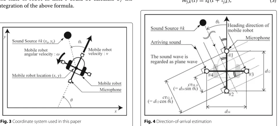
In this subsection, wheel-based odometry is described. Coordinate system used in this paper is shown in Fig. 3. Let denote the state of the robot asx=x y θTand the time evolution of this state is,
f(x)= x+ ⎡ ⎣vvcossinθθ
ω ⎤
⎦t, (1)
where v and ω are measured robot velocity and
angu-lar velocities, which are measured from wheel rotation. The state of robot in time t could be calculate by the integration of the above formula.
Fig. 3Coordinate system used in this paper
(ii) Estimation of direction-of-arrival using microphone array
The angle between the direction of sound sourcek and the heading of the mobile robot is represented byθk, as
shown in Fig. 4. θk is called direction-of-arrival (DOA).
We are going to estimate θk using signals recorded by
microphone array. To estimateθk, we utilize the relation between θk and propagation time differences of sound between the elements of microphone array. Propagation time differences of sound between the elements are mea-sured by cross-correlation method. At first, we describe the cross-correlation method.
Assuming that sound signals propagated from the sound source k would delayτi,k andτj,k, the received signal on microphone elementsiandj,mi,kandmj,k, would be,
mi,k(t)=sk(t+τi,k), (2)
mj,k(t)=sk(t+τj,k), (3)
where sk(t) represents the sound signal of the sound
sourcekat timet. With these signals and given window lengthw, cross-correlation functionfij,k(t)is calculated as,
fij,k(t)=
t t−w
mi,k(τ )mj,k(τ−t)dτ. (4)
The peak of fij,k(t) is at the time when mi,k and mj,k
have maximum number of correlation, namely at the time τij,k ≡ |τi,k−τj,k|. Using this nature of cross-correlation, we can obtain the propagation time difference of the sound from sound sourcekbetween the elementsiandjas,
τij,k=argtmax fij,k(t)
. (5)
Second, we describe the detail of DOA estimation using the relation between propagation time differences and θk. Assume that we are going to use a microphone array which is shown in Fig. 4. The robot has 4 microphones for the following reason. The microphone array with 2 microphones is the minimum equipment to measure the DOA in two-dimension, however it cannot estimate DOA uniquely as it cannot distinguish whether the sounds come from front or back. The microphone array with 3 microphones is sufficient for unique DOA estimation, however it requires 3 combinations ofτij,kto achieve spa-tially symmetrical estimation of DOA. The microphone array shown in Fig. 4 can estimate DOA uniquely and only 2 combinations (τ12,k and τ34,k) are required for
symmetrical estimation DOA.
If the microphone array and sound sourcekare enough distant from each other, the sound wave from sound source k to the microphone array can be regarded as a plane wave. This wave reaches to the microphone array at an angle ofθk. This angle causes the propagation time dif-ference for each element of microphone array. Measuring this propagation time difference, we can estimateθk.
From the relation of the time difference of arrival,τ12,k,
and distance between microphones, d12, the DOA of
sound sourcek,θk, would be given by solving,
cτ12,k = d12sinθk, (6)
wherecrepresents the sound velocity.
Similarly, this relation is applied to the elements 3 and 4. Let us denote the propagation time difference of the elements 3 and 4 from sound sourcekbyτ34,k, and the dis-tance between the elements 3 and 4 byd34. The following
equation is derived in a similar way.
cτ34,k = d34cosθk. (7)
By solving equations (6) and (7) for θk, the following
equation is obtained,
θk =atan2
τ12,k
d12
,τ34,k
d34
. (8)
Here atan2(x,y) represents the function which returns the angle of the position (x, y) from x-axis in the range of [−π π]. Using this equation,θkcan be estimated.
In practical use, it is known that the DOA estimation can be inaccurate by several reasons such as multi-path. To examine the accuracy of the DOA estimation, the proposed method use the following valueτk.
τk ≡1−
cτ12,k
d12 2
+
cτ34,k
d34 2
. (9)
If the propagation time differences are correctly esti-mated,τkbecomes 0. This valueτkcan be considered as a likelihood of the DOA estimation result. In the pro-posed method, if |τk| exceeds a certain threshold, the estimated DOA is regarded as inaccurate value and it is replaced by the last DOA which does not exceed the threshold.
Considering the real environment, the received signal consists of To separate these, we use the band pass filter to identify each beacon.
(iii) Prediction of the DOA from estimated location and pose The DOA is predicted based on estimated location and pose to be compare to the measured DOA and feedback the error in later step. Prediction is conducted by the following equation. Given nsound sources with known locations, each sound source location is represented byxk,
yk, wherekis the sound source number. The relationship
betweenxk,yk,θkand the locationx,yand poseθ of the
robot is expressed by,
⎡ ⎢ ⎢ ⎢ ⎣ ˆ θ1 ˆ θ2 .. . ˆ θn ⎤ ⎥ ⎥ ⎥ ⎦= ⎡ ⎢ ⎢ ⎢ ⎣
tan−1((y1−y)/(x1−x))−θ
tan−1((y2−y)/(x2−x))−θ
.. .
tan−1((yn−y)/(xn−x))−θ
⎤ ⎥ ⎥ ⎥ ⎦. (10)
With this equation, the DOA is predicted from esti-mated location and pose and known sound source locations.
(iv)Self-localization using odometry and DOA
Location and pose of the robot which are estimated by odometry and estimated DOA are integrated by Extended Kalman filter. The proposed method utilize extended Kalman filter for self-localization by regarding equation (1) as state transition equation and equation (10) as observation equation. With these equations, the state of the robot x is estimated. We describe the detail of the extended Kalman filter in the following.
Let us define:xˆt−t/t asx on the timetwhich is
esti-mated on the timet −t; xˆt/t andxˆt/t+t asx on the
time t and t + t which is estimated on the time t;
Pt−t/t,Pt/tandPt/t+tthe covariance matrix of the
consists of the DOA estimated by (ii) is represented as
y=[θ1,θ2,. . .,θn]Tand the right member of the equation
(10) is represented ash(x). Self-localization of the robot using extended Kalman filter is formulated as,
K = Pt−t/tHT
HPt−t/tHT+R
−1
, (11) ˆ
xt/t = ˆxt−t/t+K(y−h(xˆt−t/t)), (12)
Pt/t = Pt−t/t−KHPt−t/t, (13)
ˆ
xt/t+t = f(xˆt/t), (14)
Pt/t+t = FPt/tFT+Q. (15)
HereRis the covariance matrix of the observation error, which is the error of the DOA estimation, andQis the covariance matrix of the system noise, which is the error of the location and pose of the robot. F andH are the Jacobians which are defined as,
F =
∂f
∂x
x=ˆxt/t
, H =
∂h
∂x
x=ˆxt/t
. (16)
By steppingt+t → t,t → t−t, the estimated self-locationxˆt/twould be calculated recursively.
Conditions of experiment Common condition
To examine the ability of the proposed method, three types of experiments were conducted. At first, we note the common conditions of these. In the experiments, we have supposed the house-cleaning robot and its trajectory. The sound sources layout and the trajectory of the robot are shown in Fig. 5. The experiments were executed for 10
Fig. 5Sound sources layout and the trajectory of the robot for experiment
Fig. 6Robot used for experiment. The marker was used to obtain ground truth using optical tracking
times respectively. The sampling frequency of the veloc-ity and angular velocveloc-ity, which were obtained by wheel rotation, was 5 Hz.
The picture of the robot used in the experiment is shown in Fig. 6. On the robot, 4 elements of microphone array were placed, and the signals of them were acquired to personal computer using A-D converter. The sounds are recorded by MEMS microphone (SPU0414HR5H-SB, Knowles), which are the elements of the microphone array. The A-D converter was NI USB-6212 (National Instruments) and the sampling frequency of the A-D con-verter was 100 kHz. iRobot Create (iRobot Corporation) was used in the experiment. The velocityvand angular velocity ω was obtained at 5 Hz using the Open Inter-face of the iRobot Create. Thesev,ωand the signals from microphone array are used for self-localization of each method.
The distances of the elements of the microphone array
d12,d34 were both set to be 250 mm. The sampling
separation were designed to have low-frequency cutoff at
fL×0.99(Hz) andfH×1.01(Hz) for given sound with
fre-quency band [fL fH] (Hz). The filters were implemented
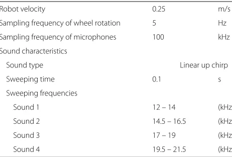
as finite impulse response filter which has tap number of 200. Other conditions are described in Table 1. The frequencies of the sound sources were chosen by consid-ering frequency band of background noise and sharpness of autocorrelation of signal. The level of the sound sources were adjusted to maximum volume to achieve enough signal-to-noise ratio.
The window lengthwwas set to be 0.12 s. The thresh-old of the value|τk|was set to be 0.2, and if it exceeds the threshold, the DOA estimation is regarded as an inac-curate estimation.R,Qused in the extended Kalman filter were set as,
R=1×10⁶
⎡ ⎢ ⎢ ⎣
τ1 0 0 0
0 τ2 0 0
0 0 τ3 0
0 0 0 τ4
⎤ ⎥ ⎥ ⎦+5I,
Q= ⎡ ⎣2 0 00 2 0
0 0 10
⎤ ⎦.
(17)
Hereτ1,τ2,τ3andτ4are the values of equation (9)
for each sound source. Each of the constants are decided preexperimentally.
The ground truth of the location and pose of the robot need to be measured for evaluating the self-localization methods. In this experiment, the measurement of the ground truth was achieved by motion capture system with 18 cameras (OptiTrack Prime 41, OptiTrack) and analysis software (Motive body, OptiTrack). The frame rate of the system was set to 120 frames per second. The robot was equipped with 8 markers on the top of it.
Table 1Condition of experiments
Robot velocity 0.25 m/s
Sampling frequency of wheel rotation 5 Hz
Sampling frequency of microphones 100 kHz
Sound characteristics
Sound type Linear up chirp
Sweeping time 0.1 s
Sweeping frequencies
Sound 1 12 – 14 (kHz)
Sound 2 14.5 – 16.5 (kHz)
Sound 3 17 – 19 (kHz)
Sound 4 19.5 – 21.5 (kHz)
Conditions of specific experiments
Conditions of experiment 1: without occlusion or reflective wave The robot runs on the trajectory without any obstacles or walls. This experiment was conducted to evaluate the localization error without these disturbances.
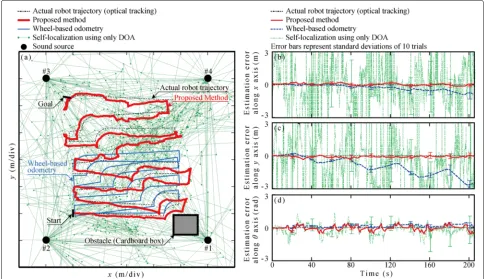
Conditions of experiment 2: occlusion of the sound source This experiment was conducted to evaluate the effect of the occlusion of sound source on the localiza-tion accuracy. Cardboard box (approximate dimensions height:1 m, width:0.5m for each) was placed as shown in Fig. 5 and it completely occlude sound source 1.
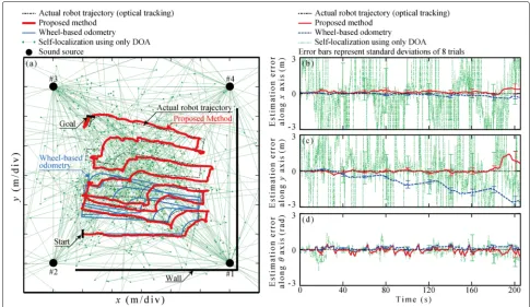
Conditions of experiment 3: reflective wave from wall This experiment was conducted to evaluate the effect of reflective wave on the localization accuracy. Wall was placed as shown in Fig. 5.
Comparative methods
Wheel-based odometry We compared the proposed method to the odometry using only wheel rotation, which is one of the conventional self-localization method and also a part of the proposed method. This method esti-mates self-location by updating x with equation (1) for every measurement. This is the odometry using only wheel rotation. As is clear from the equation (1), the mea-surement errors of v and ω are not considered in this method although this method accumulates them. Because of this reason, this method has disadvantage that if there are the measurement errors onvandω, they are accumu-lated over time.
Self-localization using only DOA estimation If loca-tion and DOA of each sound source are known, the location and pose of the robot can be estimated from them using equation (10). Let us define the difference of both members of the equation (10) as a functionhs(θ,x), where
θ ≡ θ1θ2. . . θn
T
. If given DOA and location and pose of the mobile robot are consistent,hs(θ,x)takes the value
0. Hereby, with givenθ, self-localization by only DOA is achieved by,
ˆ x = min
x hs(θ,x). (18)
When conducting (18), all DOA are assumed to be cor-rect in this method. As mentioned before, the DOA is not always accurate as it is influenced by several distur-bances such as reflective waves. Because of these reasons, the estimated location and pose of the robot is affected by the error of DOA.
Results and discussion
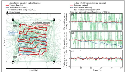
Fig. 7Result of experiment 1:aAn example of self-localization result in experiment 1btime variation of self-localization error alongxctime variation of self-localization error alongydtime variation of self-localization error alongθ
moved the robot open loop control, the real trajectory obtained by the optical tracking is slightly different from that of Fig. 5. Figures 7b–d shows the relation between time and self-localization errors along each axis for this experiment. The movie of the experiment and estimation are shown in Additional File 1.
From Fig. 7a, we can confirm that the proposed method estimates the real trajectory. Wheel-based odometry failed to estimate self-location as the distance between estimation result and actual trajectory was spread over time. However, sometimes the estimation result of the proposed method was incorrect when the odometry also have incorrect estimation. The proposed method com-bines the odometry and DOA and influenced by it.
From Fig. 7b–d, we can confirm that wheel-based odometry have estimation errors which increase over time. It indicates that measured velocity and angular velocity contains certain amount of errors and these are accumulated over time as mentioned before. By contrast, the proposed method does not have the errors which increase with time and achieve the estimation around the actual values. The standard deviation of them are almost equal to that of odometry and relatively smaller than that of the self-localizaiton using only DOA.
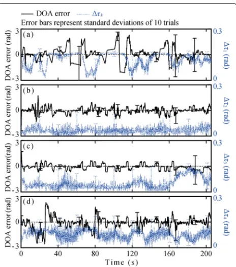
Figure 8 shows the DOA estimation error andτk for each sound sources over time. As we have defined before,
Table 2Localization error of experiment 1( lower is better )
Method Error direction Mean Standard deviation Unit
Wheel-based odometry Location (xaxis,yaxis) ( -0.039, -0.672) ( 0.22, 1.54) (m)
Pose 0.077 0.24 (rad)
Self-localization using only DOA Location (xaxis,yaxis) ( 2870, -1920) ( 4020, 2790) (m)
Pose -0.069 0.48 (rad)
Proposed Method Location (xaxis,yaxis) ( 0.040, -0.069) ( 0.20, 0.20) (m)
Pose -0.022 0.27 (rad)
τk shows the likelihood of the DOA estimation. If the τk was large, the DOA estimation result can be consid-ered incorrect.τk were used inR, which was shown in the equation (17) and represents the variation of obser-vation. Ifτk becomes large, the corresponding element
ofRalso becomes large and it will prevent the feedback of incorrect DOA from sound source k. By using these values, the estimation results can be stable even if the DOA error is huge. For example, the effect of it can be confirmed from Fig. 8d. Although the DOA estima-tion error was huge from 0 s to 40 s for sound source 4 and Self-localization using only DOA could not estimate the correct, the error does not affect to the localization result of the proposed method as shown in Fig. 7b–d. The other example can be found in Fig. 8a and c. From
160 s to 200 s, the variation of the DOA error was rel-atively large. However, the large variation did not affect to the estimation result as the value of τk was also large.
Table 2 shows the mean and standard deviation of estimation errors of the location x,y and the pose for each methods. From the experimental results, proposed method estimated the self-location with lower drift and variation of the estimation.
Experiment 2: occlusion of the sound source
Figure 9a shows an example of the self-localization results by each method for experiment 2. Figure 9b–d shows the relation between time and self-localization errors along each axis for this experiment.
Fig. 10DOA error andτkfor each sound sources on experiment 2:a sound source 1bsound source 2csound source 3dsound source 4
From Fig. 9a, we can confirm that the localization result by proposed method was similar to that of optical tracking. However, it was relatively inaccurate than that of Fig. 7a.
Figure 10 shows the DOA estimation error andτkfor
each sound sources over time. The effect of the occlu-sion of sound source 1 can be considered in Fig. 10a. By comparing to the Fig. 8a, the DOA estimation result in experiment 2 have much error for most of the time. How-ever, sometimes the DOA estimation was correct even the sound source 1 was occluded. In this case,τk of sound source 1 indicates that the DOA of it is not accurate, and as we can see in Figures 9b–d, the DOA error did not have much effect to the localization result.
The reason of these can be considered as the diffracted wave from the sound source. With the diffracted wave, the microphones will receive multiple waves at once. It
makes that estimatedτ12,kandτ34,kfrom them would
con-flict and the concon-flict was detected by τk. When τk
was high, the proposed method suppress the feedback of sound source k. In this case, it prevented the inaccurate DOA, which was affected by obstacle to be feedbacked.
Table 3 shows the mean and standard deviation of esti-mation errors of the locationx,yand the pose for each methods. The estimation errors are similar to that of experiment 1, and localization error increased for approx-imately 60 mm. From this result, we can confirm that the occlusion does not affect to the localization accuracy much if the other sound sources are not occluded.
Experiment 3: reflective wave from wall
Figure 11a shows an example of the self-localization results by each method for experiment 3. Overall, pro-posed method shows similar estimation result compared to the previous 2 experiments in this example.
Figures 11b–d shows the relation between time and self-localization errors along each axis for this experiment. As we have moved the robot open loop control, the robot runs into wall 2 times and we have removed these results and conducted analysis with 8 trials. The estimation error of the proposed method was high at the end of the esti-mation. The reason of this error can be considered as reflective wave from the wall. As shown in Fig. 12, the DOA estimation error at that time was relatively high for sound source 3. Sound source 3 was facing to the center of field and its frequency was relatively high, When the robot was at the side of the sound source 3, the reflec-tive wave from the wall could be larger than the direct wave because of its directivity. If the reflective wave was dominant in the microphone signal, the peak of the cor-relation function between microphones would exist at the time which represents time difference of reflective wave. In this condition, the reflective wave can be regarded as a sound source, andτ12,kandτ34,k did not conflict as much as that of diffracted wave in experiment 2 so that the value of theτkwas not high. This problem can be solved by using omni-directional loudspeaker for the sound sources.
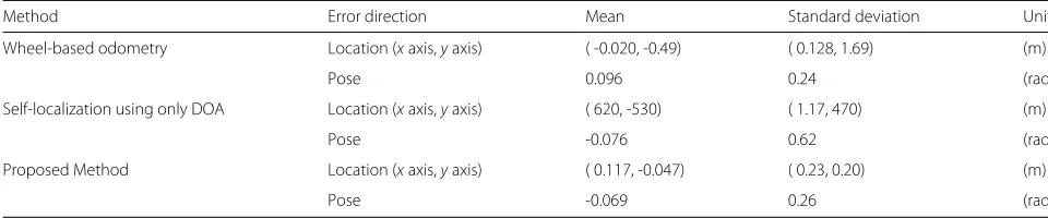
Table 4 shows the mean and standard deviation of esti-mation errors of the locationx,yand the pose for each
Table 3Localization error of experiment 2( lower is better )
Method Error direction Mean Standard deviation Unit
Wheel-based odometry Location (xaxis,yaxis) ( -0.098, -0.590) ( 0.32, 1.56) (m)
Pose 0.154 0.28 (rad)
Self-localization using only DOA Location (xaxis,yaxis) ( 1660, -2360) ( 6300, 18900) (m)
Pose -0.046 0.65 (rad)
Proposed Method Location (xaxis,yaxis) ( 0.045, -0.088) ( 0.18, 0.23) (m)
Fig. 11Result of experiment 3:aAn example of self-localization result in experiment 3btime variation of self-localization error alongxctime variation of self-localization error alongydtime variation of self-localization error alongθ
methods. The estimation error of the proposed method was relatively higher than that of experiment 1, however, it is still acceptable for house-cleaning robot.
From these results, we can confirm that even with the obstacles or the walls, the proposed method can provide estimation result.
Conclusion
In this paper, we have proposed the low-cost self-localization method which uses 4 elements of micro-phones, wheel rotation and known sound sources as beacons. The proposed method consists of following 4 steps. The proposed method (i) execute wheel-based odometry, (ii) estimate DOA of the sound sources using sounds recorded by the elements of the microphone array, (iii) predict the DOA of the sound sources from esti-mated location and pose, and (iv) conduct self-localization by integrating all of the information. To evaluate the proposed method, experiments were conducted. The proposed method was compared with the conventional methods, which were wheel-based odometry and self-localization using only DOA. Three types of experiments were conducted to evaluate the proposed method with the occlusion or reflection of the sound. In experiment, the robot run on the trajectory which was supposed
Table 4Localization error of experiment 3( lower is better )
Method Error direction Mean Standard deviation Unit
Wheel-based odometry Location (xaxis,yaxis) ( -0.020, -0.49) ( 0.128, 1.69) (m)
Pose 0.096 0.24 (rad)
Self-localization using only DOA Location (xaxis,yaxis) ( 620, -530) ( 1.17, 470) (m)
Pose -0.076 0.62 (rad)
Proposed Method Location (xaxis,yaxis) ( 0.117, -0.047) ( 0.23, 0.20) (m)
Pose -0.069 0.26 (rad)
the house cleaning robot. The experiments were con-ducted for 10 trials. As results, without any obstacles or walls, the mean of the estimation errors by wheel-based odometry were 670 mm and 0.08 rad, and those of self-localization using only DOA were 2870 m and 0.07 rad in the worst case. In contrast with these meth-ods, proposed method results in 69 mm, 0.02 rad as the worst estimation error of self location and pose. Under the condition with occlusion, it affected to the DOA estimation of occluded sound source and proposed method detected the incorrect DOA. The increase of self-localization error by occlusion was approximately 60 mm in this condition. Under the condition with reflec-tive wave, the localization error of the proposed method increased because of the directivity of sound source and reflective wave. It need to be clarified whether the omni-directional speaker can solve this problem. From the results, the proposed method is enough feasible for indoor self-localization.
As future works, the effect of sound sources layout on the estimation accuracy and the effect of the multi-path on DOA estimation error need to be considered.
Additional file
Additional file 1: Overview of experiment and estimated results.In this movie, one trial of experiment and corresponding estimated results are shown. (MP4 12.9 kb)
Abbreviations
SLAM: Simultaneous localization and mapping; DOA: Direction-of-arrival.
Competing interests
The authors declare that they have no competing interests.
Authors’ contributions
All authors equally contributed. All authors read and approved the final paper.
Author details
1School of Integrative and Global Majors, University of Tsukuba, Ibaraki, JP. 2Graduate School of Systems and Information Engineering, University of Tsukuba, Ibaraki, JP.3Faculty of Engineering, Information and Systems, University of Tsukuba, Ibaraki, JP.
Received: 9 April 2015 Accepted: 13 August 2015
References
1. Borenstein J, Feng L (1996) Gyrodometry: a new method for combining data from gyros and odometry in mobile robots. In: International Conference on Robotics and Automation, Minneapolis Vol. 1. pp 423–428. doi:10.1109/ROBOT.1996.503813
2. Lindstrom M, Eklundh JO (2001) Detecting and tracking moving objects from a mobile platform using a laser range scanner. In: 2001 IEEE/RSJ International Conference on Intelligent Robots and Systems (IROS). IEEE, Maui Vol. 3. pp 1364–1369. doi:10.1109/IROS.2001.977171
3. Murray D, Little JJ (2000) Using real-time stereo vision for mobile robot navigation. Auton Robot 8:161–171. doi:10.1023/A:1008987612352 4. Maeyama S, Ohya A, Yuta S (1995) Non-stop outdoor navigation of a
mobile robot-retroactive positioning data fusion with a time consuming sensor system. In: Intelligent Robots and Systems 95. ’Human Robot Interaction and Cooperative Robots’, Proceedings. 1995 IEEE/RSJ International Conference On Vol. 1. pp 130–1351.
doi:10.1109/IROS.1995.525786
5. Aarabi P, Zaky S (2001) Robust sound localization using multi-source audiovisual information fusion. Inf Fusion 2(3):209–223.
doi:10.1016/S1566-2535(01)00035-5
6. Thrun S, Leonard J (2008) Simultaneous localization and mapping. Springer handbook of robotics. In: Siciliano B, Khatib O (eds). Springer handbook of robotics. Springer, Heidelberg. pp 871–889.
doi:10.1007/978-3-540-30301-5_38
7. Thrun S, Fox D, Burgard W, Dellaert F (2001) Robust Monte Carlo localization for mobile robots. Artif Intell 128(1-2):99–141. doi:10.1016/S0004-3702(01)00069-8
8. Miura H, Yoshida T, Nakamura K, Nakadai K (2011) SLAM-based online calibration of asynchronous microphone array for robot audition. In: 2011 IEEE/RSJ International Conference on Intelligent Robots and Systems (IROS), San Francisco. pp 524–529. doi:10.1109/IROS.2011.6048869 9. Valin JM, Rouat J, Michaud F (2004) Enhanced robot audition based on
microphone array source separation with post-filter. In: 2004 IEEE/RSJ International Conference on Intelligent Robots and Systems (IROS), Sendai Vol. 3. doi:10.1109/IROS.2004.1389723
10. Asono F, Asoh H, Matsui T (1999) Sound source localization and signal separation for office robot “JiJo-2”. In: Proceedings. 1999 IEEE/SICE/RSJ. International Conference on Multisensor Fusion and Integration for Intelligent Systems. MFI’99. IEEE, Taipei. pp 243–248.
doi:10.1109/MFI.1999.815997
11. Yamamoto S, Valin JM, Nakadai K, Rouat J, Michaud F, Ogata T, Okuno HG (2005) Enhanced robot speech recognition based on microphone array source separation and missing feature theory. In: Proceedings - IEEE International Conference on Robotics and Automation, Barcelona Vol. 2005. pp 1477–1482. doi:10.1109/ROBOT.2005.1570323 12. Saruwatari H, Mori Y, Takatani T, Ukai S, Shikano K, Hiekata T, Morita T
(2005) Two-stage blind source separation based on ICA and binary masking for real-time robot audition system. In: 2005 IEEE/RSJ International Conference on Intelligent Robots and Systems (IROS), Edmonton. pp 209–214. doi:10.1109/IROS.2005.1544983
13. Nakadai K, Yamamoto S, Okuno HG, Nakajima H, Hasegawa Y, Tsujino H (2008) A robot referee for rock-paper-scissors sound games. In: Proceedings - IEEE International Conference on Robotics and
Automation, California. pp 3469–3474. doi:10.1109/ROBOT.2008.4543741 14. Nakadai K, Nakajima H, Murase M, Okuno HG, Hasegawa Y, Tsujino H
Robot-Embedded and In-Room Microphone Arrays. J Robot Soc Japan 25(6):979–989. doi:10.7210/jrsj.25.979
15. Valin J.-m., Rouat J, Dominic L (2003) Robust Sound Source Localization Using a Microphone Array on a Mobile Robot. In: 2003 IEEE/RSJ International Conference on Intelligent Robots and Systems (IROS), Las Vegas. pp 1128–1233. doi:10.1109/IROS.2003.1248813
16. Silverman HF, Patterson WR, Flanagan JL (1997) The Huge Microphone Array (HMA). J Acoust Soc America 101(5):3119. doi:10.1121/1.418967 17. Weinstein E, Steele K, Agarwal A, Glass J (2004) Loud: A 1020-node
modular microphone array and beamformer for intelligent computing spaces. Comput Sci Artif Intel Lab Tech Rep MIT-LCS-TM:1–18. http://129. 69.211.95/pdf/mit/lcs/tm/MIT-LCS-TM-642.pdf
18. Kawagishi T, Ogiso S, Mizutani K, Wakatsuki N (2014) Mobile Robot Localization using Sound Source Direction obtained by Small Element Number of Microphone Array. In: Proceedings of the 2014 JSME Conference on Robotics and Mechatronics. pp 2–208
19. Ogiso S, Kawagishi T, Mizutani K, Wakatsuki N, Zempo K (2015) Relation between sound sources layout and error of self-localization method in two-dimension for mobile robot using microphone array. In: Proceedings of the 22th International Congress on Sound & Vibration (ICSV22), Florence. pp 01–010626
20. Zempo K, Mizutani K, Wakatsuki N (2013) Localization of Acoustic Reflective Boundary Using a Pair of Microphones and an Arbitrary Sound Source. Japan J Appl Phys 52(7S):07–06
21. Zempo K, Mizutani K, Wakatsuki N (2013) Suppression of Noise Using Small Element Number of Microphone Array in Reflective. In: Proceedings of the 20th International Congress on Sound & Vibration (ICSV20), Bangkok. pp 05–649
22. Mizutani K, Ebihara T, Wakatsuki N, Mizutani K (2009) Locality of area coverage on digital acoustic communication in air using differential phase shift keying. Japan J Appl Phys 48(7 PART 2):07–07. doi:10.1143/JJAP.48.07GB07
Submit your manuscript to a
journal and benefi t from:
7Convenient online submission 7 Rigorous peer review
7Immediate publication on acceptance 7 Open access: articles freely available online 7High visibility within the fi eld
7 Retaining the copyright to your article