http://www.sciencepublishinggroup.com/j/awcn doi: 10.11648/j.awcn.20190502.12
ISSN: 2575-5951 (Print); ISSN: 2575-596X (Online)
Design Optimization of Tracking Area List in Lte Using 2D
Markov Model
Mohammed Daffalla Elradi, Lamia Osman Widaa
Communication Systems Engineering Department, University of Science and Technology, Khartoum, Sudan
Email address:
To cite this article:
Mohammed Daffalla Elradi, Lamia Osman Widaa. Design Optimization of Tracking Area List in Lte Using 2D Markov Model. Advances in Wireless Communications and Networks. Vol. 5, No. 2, 2019, pp. 52-56. doi: 10.11648/j.awcn.20190502.12
Received: July 27, 2019; Accepted: November 5, 2019; Published: November 13, 2019
Abstract:
In LTE there is a logical grouping of cells called Tracking Area (TA) and TAs are further grouped into Tracking Area List (TAL). Signaling overhead is greatly affected by the size of the TA and TAL respectively. Designing an optimum TAL would greatly reduce signaling overhead resulting from Tracking Area Update (TAU) and Paging procedures, which in return maximizes the network performance. This paper adopts a 2D Markov model that can be used for design optimization of TAL in LTE system by estimating the number of users in a cell within a time slot and the probability of the next location they might move to, as users move from and into cells periodically. The model was simulated in Matlab simulation software. The 2D Markov model was used to calculate TAU overhead, paging overhead and the total signaling overheads. The numerical results show that our model probably reduces the signaling overhead by about an average of 56% than that of the conventional TA scheme.Keywords:
2D Markov Model, Signaling Overhead, Tracking Area, Tracking Area List1. Introduction
Mobility management is turning out to be one of the most essential prerequisites for any wireless network services. Mobility management aims at tracking the location of the user.
In LTE networks there is a logical grouping of cells called Tracking Area (TA), which indicates the location of the UE [10]. TAs are further grouped into TA List (TAL), which gives more flexibility to the network’s configuration and has the potential of improving the network performance in terms of location management [15].
The Tracking Area (TA) is defined as an area in which a UE may move freely without updating its location. A UE performs a Tracking Area Update (TAU) whenever it changes TA. The size of the TA affects both the paging signaling overhead and the location update overhead; i.e. a small size TA reduces the paging signaling overhead, while a large size TA reduces the location update overhead [1-11]. Tracking Area scheme encounters some limitations that include ping pong effect, mass mobility signalling congestion and symmetry limitation which are discussed in [2-3].
In LTE, a new scheme to overcome the limitations of TA
has been introduced; which is referred to as Tracking Area List (TAL). The Mobility Management Entity (MME) assigns the TAL to the UE via the location update procedure. The location of the UE is tracked at the TAL level. Cells can assign a Tracking Area List (TAL) to each UE, and each cell can potentially assign different TALs to different UEs. This allows more flexible TA configuration and overcomes some of the limitations of the conventional TA. Probably, TAL scheme can eliminate the frequent updates that arise when a UE keeps hopping between two or more adjacent cells in different TAs (the so called ping-pong effect) [5].
A UE receives a TAL from a cell, and keeps it until it moves to a cell that is not included in its TAL. When the UE moves away from the current TAL, the UE is allocated a new TAL whose central TA is the TA where the UE currently resides.
TAL to the UE through the location update procedure.
Figure 1. TAL structure in LTE.
In (Figure 1 (1)), when the UE performs the location update in TA 2, the MME assigns TAL 1 to the UE, where TAL 1 = {TA 1, TA 2, TA 3} centred at TA 2. Each eNodeB periodically broadcasts its Tracking Area Identity (TAI), which is detected by the UE when it changes the location [9]. If the broadcast TAI is found in its TAL, the UE will move freely in its TAL. Otherwise, UE will perform the location update procedure to inform the MME that it has migrated from the current TAL [12]. For instance, when the UE moves from Cell 4 (Figure 1 (1)) to Cell 7 (Figure 1 (2)), the broadcast TA 4 identity is not found in TAL 1, and the UE executes the location update procedure to inform the MME that the UE has moved out of TAL 1. Then the MME assigns a new TAL to the UE. In Figure 1, the assigned TAL is TAL 2 = {TA 3, TA 4, TA 5}. Noting that the TAL is assigned on a per-user basis (i.e., the different UEs may have different TALs), and the newly assigned TAL may overlap with the previously assigned TAL. In Figure 1, TA 3 is included in both TAL 1 and TAL 2 [3].
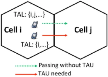
UEs in one cell may have different TALs, depending on the cells from which the TALs are assigned [4]. Figure 2 below illustrates two UEs in cell i moving towards cell j. The UEs are assigned different TALs, which affect the TAU overhead calculation. If cell j is included in the TAL of cell i, then no TAU overhead is needed for UEs having i’s list and moving to cell j. This is the case for the upper UE in the figure. On the other hand, the UE below should perform TAU because j isn’t included in its list.
Figure 2. UEs are assigned to different TALs in one cell.
From the above discussion, it can be concluded that in designing TAL for a network, it is necessary to reduce the total signaling overhead. In this paper we will propose a feasible 2D Markov model to reduce the total signaling overhead.
The rest of this paper is organized as follows:
Section II discusses some related work to the design optimization of TAL. In section III the system model is described. Section IV discusses the results obtained from the 2D Markov model and eventually, section V contains the conclusion.
2. Related Work
Many previous researches aimed to propose some mechanisms for reducing signaling overhead in LTE. TAL concept is expected to reduce the overall signaling overhead when compared to conventional TA concept. In [8], the authors proposed a scheme for adaptive design of TAL, which validated the assumption that a TA consists of only one cell and TAL can be adaptively designed for each UE, by assuming uniform mobility model of UEs to simplify the analysis. TAL for a UE is designed as rings of cells (TAs) from the last cell (TA) the location had been updated as a preliminary work to the optimal design of TAL, by applying the concept of movement-based location registration [14]. The optimal TAL can be achieved by deriving optimal movement threshold periodically using binary search algorithm, based on measured mobility and traffic characteristics of a UE during the time interval between two successive session arrivals.
In [4] the authors proposed a dynamic method for allocating and assigning TALs for LTE networks. This method is called “Rule of thumb”. The optimum conventional TA design was compared with the proposed TAL; it was found that TAL works best if a dynamic rapid reconfiguration is applied for different time intervals. The Rule of thumb method is simple and might not result in an optimum TAL configuration because each cell in the network is inconsiderately optimizing the signaling overhead according to their own data and does not take into consideration the impact of the other cells on their modified TAL. In this paper we will propose a 2D Markov model that can be used for design optimization of TALs in LTE system.
3. Method
3.1. Cell, TA, and TAL Structures
To design a mathematical approach to analyze the signaling cost of the 2D Markov model for the design of TAL-based scheme, the structures of a cell, a TA, and a TAL should be assumed.
3.1.1. Cell Structure
3.1.2. TA Structure
Assume that all the TAs in the network have the same structure consisting of one cell, hence we have 20 TA.
3.1.3. TAL Structure
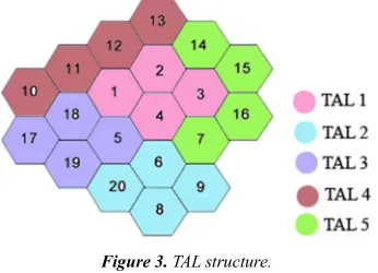
The number of TAs in each TAL is 4; hence we have 5 TALs as shown in Figure 3.
Figure 3. TAL structure.
In this network structure, there are 5 TALs; each is composed of 4 TAs as follows:
TAL1= {TA1, TA2, TA3, TA4} TAL2= {TA6, TA8, TA9, TA20} TAL3= {TA5, TA17, TA18, TA19} TAL4= {TA10, TA11, TA12, TA13} TAL5= {TA7, TA14, TA15, TA16}
3.2. 2D Markov Walk
There are two types of 2D scenarios for the mobility management of wireless communication networks: mesh cell structure and hexagonal cell structure. In the mesh cell structure, each cell is a square of identical size with four neighbors, where the UE can move from one cell to any of the four neighbour cells with specific probabilities. In the hexagonal cell structure, each cell is a hexagon of identical size with six neighbors and the UE can move from one cell to any of the six neighbour cells as shown in Figure 4 below [7]. This paper considers the hexagonal cell structure.
Figure 4. Six moving directions of the UE in the hexagonal cellular architecture.
3.3. Signaling Overhead Calculation
Let the cells in network be denoted by = {1,..., N} and the TAs in the network be denoted by = {1,..., T }. Each cell belongs to a TA that can be represented by t= [ ,..., ] where is the TA of cell i. TA design t can be represented by an N × N symmetric and binary matrix S (t). Each matrix element (t) represents whether the two cells are in the
same TA or not [8-12].
1 0 (1)
For our model, as a TA is composed of only one cell then we can consider that each element in the matrix represent whether the two TAs belong to the same TAL or not., hence the matrix is of size 20×20.
Let be the number of UEs in cell i for a given time period and be the number of UEs moving from cell i to cell j. The values of and can be determined from cell load and handover data. The amount of overhead of one TAU procedure is denoted by and overhead of one paging procedure is denoted by . The call activity factor i.e. probability that a UE needs to be paged is denoted by α. The total signaling overhead i.e. sum of TAU and paging overhead is calculated as:
"#$ ∑'∈ 1∑( ∈1 h' ( 1 ) S' ( t , α c.u' t (2)
In the above equation, the first term within the parenthesis is the TAU overhead for UEs moving from cell i to cell j if the cells are not in the same TA and the second is the paging overhead for paging UEs in cell i if the two cells are in the same TA [8].
2D Markov model estimates the number of users in a cell within a time slot and the probability of the next location they might move to, as users move from and into cells periodically. These calculations are mandatory for calculating the signaling overhead.
4. Result
This section describes the performance of the proposed model. The total signaling overhead is calculated by considering the TAU signalling overhead and paging signaling overhead. Whenever a UE moves to a cell that is not included in its TAL, it performs TAU having the cost 23 and when a UE need to be paged, the paging cost is 24. Both are added to get the total signaling cost.
Numerical Results
The simulations were performed in Matlab. The one-hour time period is divided into 60 equal time intervals. Thus, the time granularity is 1 minute. The dimension of the transition probability matrix is 7×7 as the user might move into one of the six neighboring cells and also it is probable that it stays in the same cell. The parameter 5 is 0.003, which means that 0.3% of the UEs are paged.
Table 1 depicts the assumed parameters and associated values for the proposed model.
Table 1. Assumed parameters with associated values.
Parameter Description Values
N Number of cells 20
T Number of TAs 20
Cost of a single TAU 1
α
Cost of a single paging Call activity factor
5. Discussion
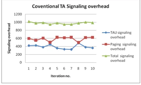
The proposed 2D Markov model performance was compared with the conventional TA design in terms of reducing signaling overhead, which was computed by estimating the number of users in each cell within a time slot. The results for the conventional TA design are presented in Figure 5 shown below, which depicts that the TAU signalling overhead was varying between 325 and 483 with an average of 392, while the paging signalling overhead was varying between 494 and 625 with an average of 585. The total signalling overhead showed an average of 977.
Figure 5. Signaling overhead results for the conventional TA.
Using the proposed 2D Markov model, the signaling overhead was calculated and the results are represented in Figure 6 shown below which depicts that the TAU signalling overhead was varying between 33 and 71 with an average of 52, while the paging signalling overhead was varying between 340 and 382 to with an average of 368. The total signalling overhead showed an average of 420.
Figure 6. Signaling overhead results for the 2D Markov model.
The total signaling overheads from the 2D Markov model TAL design is 54% to 58%better than those obtained from the optimal conventional TA designs. The 2D Markov model TAL algorithm drastically reduces the TAU overhead in relation to the paging overhead. The TAU overheads are reduced by 83% to 90% compared to the values obtained from the conventional TA design.
6. Conclusion
In this paper, an optimum 2D Markov model that reduces the total signaling overhead was proposed for Tracking Area List (TAL) in LTE. estimates the number of users in a cell within a time slot and the probability of the next location they might move to, as users move from and into cells periodically. This had been conducted by as is dividing one-hour time period into 60 equal time intervals thus, the time granularity is 1 minute. Regarding the mobility probability, it was assumed that the user might move into one of the six neighboring cells and also it is probable that it stays in the current cell. Following the proposed model, the numerical results depict that using the 2D Markov model would reduce the total signaling overhead by an average of 56% than that of conventional TA, which enhances the overall network performance. It is recommended to conduct further studies in such mathematical approaches that can lead to more optimum designs seeking better network performance.
References
[1] Vincent W.-S. Wong and Victor C. M. Leung, “Location management for next-generation personal communications networks,” IEEE Network, vol. 14, no. 5, pp. 18-24, September/October 2000.
[2] Lamia Osman Widaa, Sami Mohamed Sharif,”Design Optimization of Tracking Area List for Reducing Total Signaling Overhead in LTE Systems”, In Research gate, 2014. [3] Jaime FerragutMartínez-Vara de Rey, “Traffic and Mobility
Management in Large-Scale Networks of Small Cells”, June 2014.
[4] Razavi, S. Modarres, Di Yuan, Fredrik Gunnarsson, and Johan Moe. "Dynamic tracking area list configuration and performance evaluation in LTE." In GLOBECOM Workshops (GC Wkshps), 2010 IEEE, pp. 49-53. IEEE, 2010.
[5] Tao Deng, PingzhiFan,”Modeling and Performance Analysis of a Tracking-Area-List-Based Location Management Scheme in LTE Networks” IEEE-TVT-2016.
[6] Razavi, S. Modarres, “Planning and Optimization of Tracking Areas for Long Term Evolution Networks” Linkoping, Sweden, 2014.
[7] Q. Zhang et al.,”A 2-D random walk mobility model forWiMAX location update”, Computer Communications (2015).
[8] Xian Wang, XianfuLei, Rose Qingyang Hu, Yi Qian,”Modeling of Tracking Area List-Based Location Update Scheme in Long Term Evolution”.
[9] Liou, R., & Lin, Y. (2013). Mobility management with the central-based location area policy. Computer Networks, 57, 847-857.
[11] Razavi, Sara Modarres, and Di Yuan. "Performance improvement of LTE tracking area design: a re-optimization approach." In Proceedings of the 6th ACM international symposium on Mobility management and wireless access, pp. 77-84. ACM, 2008.
[12] Liou, R., Y. Lin, and S. Tsai. " An investigation on LTE mobility management." IEEE Transaction on mobile computing(2011), vol 12, no. 1, pp 166-176,2011.
[13] Szalka, Tamas, Sandor Szabo, and PÉTER FÜLÖP. "Markov model based location prediction in wireless cellular networks." Infocommunications Journal (2009): 40.
[14] Razavi, Sara Modarres, Di Yuan, Fredrik Gunnarsson, and Johan Moe. "Exploiting tracking area list for improving signalling overhead in LTE." In Vehicular Technology Conference (VTC 2010-Spring), 2010 IEEE 71st, pp. 1-5. IEEE, 2010.