ISSN (online): 2349-784X
Control Technique of Single Stage Grid
Connected PV System
Dinesh V. Malkhede Sachin A. Jalit
P. G Student Assistant Professor
Department of Electrical Engineering Department of Electrical Engineering P. R. Pote college of Engineering,Amravati,India P. R. Pote college of Engineering,Amravati,India
Yogita. D. Shahakar Dr. Sanjay B. Warkad
Assistant Professor Professor
Department of Electrical Engineering Department of Electrical Engineering P. R. Pote college of Engineering,Amravati,India P. R. Pote college of Engineering,Amravati,India
Abstract
This paper focused on the control technique used in CSI base grid connected PV. The system utilizes single conversion for tracking the maximum power point and interfacing the photovoltaic array to the grid. The maximum power point is maintained with a fuzzy logic controller. A proportional-resonant controller is used to control the current injected into the grid. Simulation results presented here validate the component models and the chosen control schemes.
Keywords: CSI, Proportional-Resonant Controller, Photovoltaic, FLC
________________________________________________________________________________________________________
I. INTRODUCTION
Grid-Connected PV Inverter systems have become an important power generating method and the number of these systems connected to the grid is always increasing. Therefore it is important to limit the harmonics generated by these inverters to limit adverse effects on the grid power quality. This means that the design of these inverters should follow harmonic limits set by IEEE 1547 THD of the grid voltage/current should be maintained below 5%. In grid connected PV system, DC link voltage control and inverter output current control are necessary. As power output of the PV plant largely depends on the solar irradiation and temperature, the wide variation of these parameters result in high voltage ripple in the Dc-link which propagates to the utility grid and cause power quality problem due to non-sinusoidal current injection to the grid. These wide variations in the input result in high input ripple in DC side which will propagate through the inverter to AC side and cause poor power quality and current harmonic injection into the grid.
Grid-connected PV systems using a CSI have been proposed and successfully delivered PV power to the grid, with a low total harmonic distortion (THD). However, an ac current loop is essential in the grid connected application in order to limit the current and quickly recover the grid current variation during varying weather conditions.
Fig. 1: Block diagram of PV system
II. PROPOSED SYSTEM CONTROL TECHNIQUE
To design a grid-connected PV system using a CSI, the relationship between the PV output voltage and the grid voltage is derived as follows
By neglecting inverter losses, the PV output power is equal to the grid power
VPVIPV = 1/2Ig,peak Vg,peak cos θ (1)
where θ is the phase angle, Vpv and Ipv are the PV output voltage and current, respectively, while Vg, peak and Ig, peak are the grid peak voltage and current, respectively. The grid current is equal to the PV output current multiplied by the inverter modulation index M
Ig, peak = MIPV (2)
Substituting (2) into (1), assuming unity power factor, the equation describing the relationship between the P-V output voltage and the grid voltage is
VPV =1/2MVg,peak. (3)
Therefore, in order to interface the PV system to the grid using a CSI, the PV voltage should not exceed half the grid peak voltage. The CSI is utilized to track the PV MPP and to interface the PV system to the grid. In order to achieve these requirements, three control loops are employed, namely MPPT, an ac current control loop, and a voltage loop.
III. MPPT CONTROL
The PV array power and current characteristics are highly nonlinear and are affected by the irradiance and temperature variation. Therefore, a maximum power-point tracker (MPPT) is required to handle such problems and ensure that the PV system is operating at the maximum power point (MPP). Many different MPPT techniques have been proposed. Theexisting techniques vary in simplicity, accuracy, time response, popularity, cost, and other technical aspects.
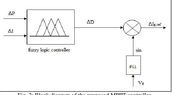
Fig. 2: Block diagram of the proposed MPPT controller.
To operate the PV at the MPP, MPPT is used to identify the optimum grid current peak value. Any conventional MPPT technique can be used. However, to prevent significant losses in power, the tracking technique should be fast enough to handle any variation in load or weather conditions. Therefore, a fuzzy logic controller (FLC) is used to quickly locate the MPP.
The inputs of the FLC are
ΔP = P(k) − P(k − 1) (4) ΔI = I(k) − I(k − 1) (5) and the output equation is
ΔD = D(k) − D(k − 1) (6)
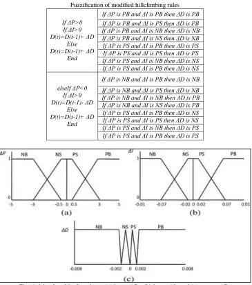
where ΔP is the PV array output power change, ΔI is the array output current change, and ΔD is the boost converter duty cycle change. To ensure that the PV output power does not diverge from the optimum point during varying weather conditions, ΔP passes through a gain controller to reverse its direction. The variable inputs and output are divided into four fuzzy subsets: positive big (PB), positive small (PS), negative big (NB), and negative small (NS). Therefore, the fuzzy rules algorithm requires 16 fuzzy control rules; these rules are based on the regulation of hill-climbing algorithm. To operate the fuzzy combination, Mamdani’s method with Max–Min is used.
The fuzzifications of the hill-climbing rules are shown in table I. After simulating the PV system and studying the behavior of the controller inputs and output, the shapes and fuzzy subset partitions of the membership function in both of inputs and output are shown in Fig. 4. The last stage of the fuzzy controller is the defuzzification where the center of area algorithm (COA) is used to convert the fuzzy subset duty cycle changes to real numbers
∆D =
∑ μn
i (Di)Di
(IJSTE/ Volume 3 / Issue 05 / 034)
Table – 1
Fuzzification of modified hillclimbing rules
If ΔP>0 If ΔI>0 D(t)=D(t-1)+ ΔD Else D(t)=D(t-1)+ ΔD End
If ΔP is PB and ΔI is PB then ΔD is PB If ΔP is PB and ΔI is PS then ΔD is PB If ΔP is PB and ΔI is NB then ΔD is NB If ΔP is PB and ΔI is NS then ΔD is NB If ΔP is PS and ΔI is PB then ΔD is PS If ΔP is PS and ΔI is PS then ΔD is PS If ΔP is PS and ΔI is NB then ΔD is NS If ΔP is PS and ΔI is PB then ΔD is NS
elseIf ΔP<0 If ΔI>0 D(t)=D(t-1)- ΔD Else D(t)=D(t-1)+ ΔD End
If ΔP is NB and ΔI is PB then ΔD is NB If ΔP is NB and ΔI is PS then ΔD is NB If ΔP is NB and ΔI is NB then ΔD is PB If ΔP is NB and ΔI is NS then ΔD is PB If ΔP is PS and ΔI is PB then ΔD is NS If ΔP is PS and ΔI is PS then ΔD is NS If ΔP is PS and ΔI is NB then ΔD is PS If ΔP is PS and ΔI is PB then ΔD is PS
Fig. 4: Membership functions: (a) input ΔP , (b) input ΔI, and (c) output ΔD.
where ΔD is the fuzzy controller output and Di is the center of max–min composition at the output membership function. The FLC computes variable step sizes to increment or decrement the duty cycle, therefore the tracking time is short and the system performance during steady-state conditions is much better than conventional method.
To ensure synchronization between the grid current and voltage, a sinusoidal signal generated by a phase-locked-loop (PLL)is multiplied by the MPPT output. Fig. 2 shows a block diagram of the MPPT structure.
IV. VOLTAGE AND CURRENT LOOP CONTROLLERS
The current controller can have a significant effect on the quality of the current supplied to the grid by the PV inverter, and therefore it is important that the controller provides a high quality sinusoidal output with minimal distortion to avoid creating harmonics. Two controllers which are used in current controlled PV inverters are the PI controller with the grid voltage feed-forward and the PR controller.
A shortcoming with the PI controller generally is that it is not able to follow a sinusoidal reference without steady state error due to the dynamics of the integral term. The inability to track a sinusoidal reference causes the need to use the grid voltage as a feed-forward term to obtain a good dynamic response by helping the controller to try to reach steady state faster. A current controller which is more suited to operate with sinusoidal references and does not suffer from the above mentioned drawback is the PR controller. The PR controller provides gain at a certain frequency (resonant frequency) and almost no gain exists at the other frequencies.
𝑦 = K𝑝𝑒 + K𝑖 es s2 + ω2
where Kp is the proportional gain, Ki is the integral gain, e is the signal error, and ωo is the fundamental angular frequency.
Fig. 5: Equivalent circuit of the CSI ac side.
From the equivalent circuit of the CSI ac side, which is shown in Fig.5 and the PR controller equations, the ac current and voltage loops are designed, where Iin is the CSI output current, Cf is the filter capacitor, Lf is the filter inductor, R is the inductor internal resistor, Ic is the current passing through the capacitor, Ig is the grid current, and Vg is the grid voltage.
Fig. 6: AC current and voltage loops.
V. SIMULATIONS AND RESULT
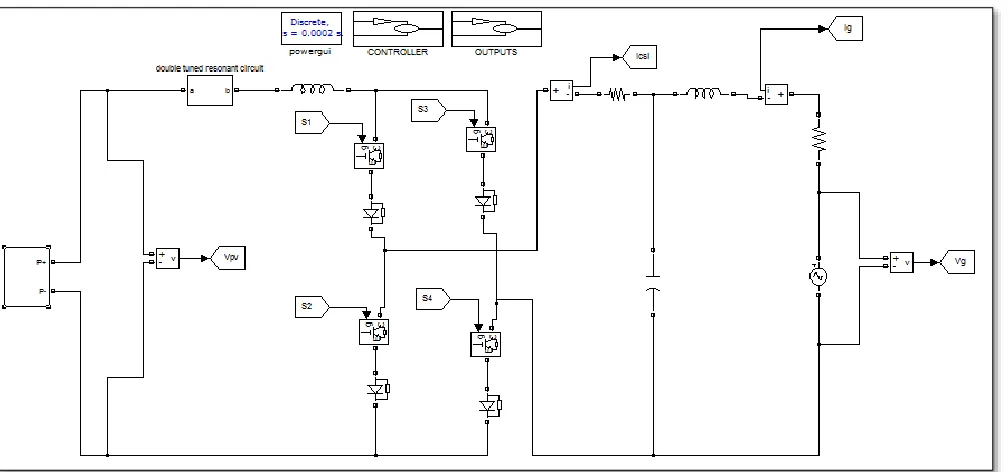
In order to validate the theoretical analysis, closed loop operation of grid connected photovoltaic system using single phase current source inverter is simulated on MATLAB/Simulink. The simulated closed loop system has taken the circuit parameter values are shown in A. The simulated PV array is connected to the Double tuned resonant filter which mitigates the DC side harmonics.
(IJSTE/ Volume 3 / Issue 05 / 034)
The regulated dc power from PV side is fed into CSI to convert it from dc power to ac power. The MPPT of this PV plant is controlled by using FLC and The PV array is simulated by using matlab/simulink is shown in Fig.7.
To ensure synchronization between the grid current and voltage, a sinusoidal signal generated by a phase-locked-loop (PLL) is multiplied by the MPPT output and produce reference signal will be sent to the PR controller. The output of the PR controller is then sent to the PWM block to generate the pulses for PV inverter. The CSI output current waveform and the Grid voltage Vg and Grid current Ig are verified through simulation results.
Fig. 8: grid current and grid voltage
Fig. 9: CSI output current
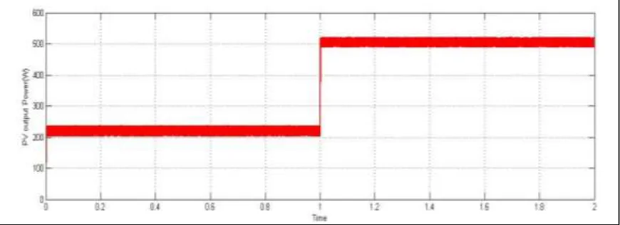
Fig. 11: PV Output Power
REFERENCES
[1] Photovoltaic Systems Engineering, Second Edition, Roger A. Messenger Jerry Ventre, CRC PRESS
[2] B. N. Alajmi, K. H. Ahmed, S. J. Finney, and B. W. Williams, “Fuzzylogic- control approach of a modified hill-climbing method for maximum power point in microgrid standalone photovoltaic system,” IEEE Trans. Power Electron., vol. 26, no. 4, pp. 1022–1030, Apr. 2011.
[3] W. Tsai-Fu, C. Chih-Hao, L. Li-Chiun, and K. Chia-Ling, “Power loss comparison of single- and two-stage grid-connected photovoltaic systems,” IEEE Trans. Energy Convers., vol. 26, no. 2, pp. 707–715, Jun. 2011.
[4] S. B. Kjaer, J. K. Pedersen, and F. Blaabjerg, “A review of single-phase grid-connected inverters for photovoltaic modules,” IEEE Trans. Ind. Appl., vol. 41, no. 5, pp. 1292–1306, Sep.–Oct. 2005.
[5] G. Petrone, G. Spagnuolo, and M. Vitelli, “A multivariable perturb and- observe maximum power point tracking technique applied to a single-stage photovoltaic inverter,” IEEE Trans. Ind. Electron., vol. 58, no. 1, pp. 76–84, Jan. 2011.
[6] E. Villanueva, P. Correa, J. Rodriguez, andM. Pacas, “Control of a single phase cascaded H-bridge multilevel inverter for grid-connected photovoltaic systems,” IEEE Trans. Ind. Electron., vol. 56, no. 11, pp. 4399–4406, Nov. 2009.
[7] N. A. Rahim, K. Chaniago, and J. Selvaraj, “Single-phase seven-level gridconnected inverter for photovoltaic system,” IEEE Trans. Ind. Electron., vol. 58, no. 6, pp. 2435–2443, Jun. 2011.
[8] B. Sahan, S. V. Ara´ujo, C. N¨oding, and P. Zacharias, “Comparative evaluation of three-phase current source inverters for grid interfacing of distributed and renewable energy systems,” IEEE Trans. Power Electron., vol. 26, no. 8, pp. 2304–2318, Aug. 2011.
[9] B. Sahan, A. N. Vergara, N. Henze, A. Engler, and P. Zacharias, “A singlestage PVmodule integrated converter based on a low-power current-source inverter,” IEEE Trans. Ind. Electron., vol. 55, no. 7, pp. 2602–2609, Jul. 2008.
[10] P. P. Dash and M.Kazerani, “Dynamic modeling and performance analysis of a grid-connected current-source inverter-based photovoltaic system,” IEEE Trans. Sustainable Energy, vol. 2, no. 4, pp. 443–450, Oct. 2011.
[11] S. Jain and V. Agarwal, “A single-stage grid connected inverter topology for solar PV systems with maximum power point tracking,” IEEE Trans. Power Electron., vol. 22, no. 5, pp. 1928–1940, Sep. 2007.
[12] A. Darwish, A. K. Abdelsalam, A. M. Massoud, and S. Ahmed, “Single phase grid connected curent source inverter: Mitigation of oscillating power effect on the grid current,” in Proc. IET Conf. Renewable Power Generation, Sep. 2011, pp. 1–7.
[13] R. T. H. Li, H. S.-H. Chung, and T. K. M. Chan, “An active modulation technique for single-phase grid-connected CSI,” IEEE Trans. Power Electron., [14] K. Hirachi and Y. Tomokuni, “A novel control strategy on single-phase PWM current source inverter incorporating pulse area modulation,” Proc. Power
Convers. Conf., vol. 1, pp. 289–294, Aug. 1997.