ANFIS Based Control for Hybrid Renewable
Energy using Voltage Lift Technique With Smart
Grid Application
P. Sakthikumaresan C. P. Kandasamy
PG Scholar Assistant Professor
Department of M.E. Power Systems Engineering Department of EEE
V.S.B Engineering College,Karur, India - 639111. V.S.B Engineering College, Karur, India - 639111.
Abstract
This paper describes and performance an adaptive neuro-fuzzy inference system (ANFIS) based energy management system (EMS) of a grid-connected hybrid system for smart grid application. The hybrid system consists of wind turbine (WT) and solar photovoltaic (PV) panels as a primary energy sources. The rectified wind output and solar panel output is given to LUO converter for boost up the DC voltage in order to connect them to a central DC grid. Then, the power has taken from the DC grid and it is given to the AC smart grid system through H-bridge inverter. The smart grid system consists of new bidirectional intelligent semiconductor transformer (BIST), high frequency ac-dc rectifier and low voltage dc-dc converter hybrid switching dc-ac converter. The smart grid system satisfied the load requirement and in case if the demand is low it will return the excess power to the grid also. On the whole, this proposed system utilizes the best use of solar and wind energy system so that the power can be generated at any time and satisfied the load demand.
Keywords: ANFIS Based EMS, Hybrid System, LUO, Bidirectional Intelligent Semiconductor Transformer (BIST), Smart Grid, Load Demand
________________________________________________________________________________________________________
I.
I
NTRODUCTIONCurrently, renewable energy sources play a major role in electrical energy generation [3],[5]. Power systems are undergoing considerable changes as generation moves from large-centralized conventional power plants to small-decentralized renewable power plants [6]. In reality, the use in these small power plants of hybrid renewable energy systems(HRES), mainly based on renewable sources presents some advantages over larger power plants, such as non-polluted, quality of power, reliable operation, low cost, direct generation, and expandability[6].
of the operation voltage are different and high-quality power is required [10]. Intelligent semiconductor transformer or solid-state transformer was planned by EPRI to replace the usual transformer in railway systems and substations, in which light weight is mandatorily required. Recently, EPRI has reported 100 KVA single-phase semiconductor transformers named intelligent universal transformer for distribution automation [9].
Since the power flow in these transformers is unidirectional, it is not properly applicable for the dc distribution and micro grid [9]-[10]. One can find some studies on the semiconductor transformer topologies with bidirectional power flow capability [7]. The topology [11] in can compensate sag/swell voltage; however, it employs heavy and bulky line-frequency transformer for isolation. The semi-conductor transformer in has not only the bidirectional power flow functions but also voltage sag compensation where high-frequency dc/dc power conversion is employed [12]. The circuit configuration, shows in Fig.3 too many active switching device counts, at least 18 IGBTs for implementing single-phase module. In three-stage structure comprised of ac/dc converter, dual-active-bridge dc/dc converter, and inverter. This paper describe a new bidirectional intelligent semiconductor transformer (BIST) for the smart distribution system.
The BIST consists of high-voltage part and low-voltage part, whose configuration is shown in Fig. 3.The high-voltage part is composed of several half-bridge ac/dc converters connected in series through high-frequency trans-formers to cope with high input voltage, while the low-voltage part is composed of bidirectional half-bridge dc/dc converter and dc/ac inverter. Section II describes the grid-connected hybrid system under study. The block diagram representation grid connected hybrid system in Section III. Section IV describes the intelligent semiconductor transformer. Simulation was performed in section V at last, Section VI discuss the conclusions resulting from this work.
II.
G
RID CONNECTED HYBRID SYSTEM FOR SMART GRIDThe grid-connected hybrid system which is collected of power from WT and PV panels .Wind rectified dc voltage and PV voltage combined to dc-dc SEPIC converters in order to connect them to a central dc grid. In this system, the renewable sources are generating at any time there is wind or solar radiation.
Wind Turbine: A.
It presents a two-blade turbine coupled to a three-phase permanent magnet synchronous generator (PMSG).This WT is represented by a model with the following sub-systems: turbine and generation system. The generation system is composed of a three-phase PMSG, rectifier, and converter [14]. Fig.2 shows the connects the WT to the dc grid, is controlled by a torque reference based maximum power point tracking (MPPT) control in order to extract the maximum available power from the WT. This MPPT control maintains the operating point of the WT on its maximum power coefficient for any wind speeds in the below-rated wind speed region, modifying the duty cycle of the WT inverter, which produces a variation of its rotational speed.
PV Panels: B.
This model presents suitable accuracy [15], and the parameters are easy to find in the profitable datasheets, which makes it perfect for the simulation of PV devices with power converters. A SEPIC power converter controlled by an ANFIS controller adapts the PV output voltage to the dc grid voltage. The controller generates the duty cycle of the PV converter to move the PV voltage to the voltage that corresponds to the maximum power point (MPPT).
LUO Converter: C.
This is a one type of dc-dc converter allow the electrical potential (voltage) at its output to be larger than, fewer than, or the same that of input and the output of the luo converter is controlled by duty cycle of the control transistor. A luo converter is basically a boost converter [1] followed by a buck-boost converter therefore it is like to a conventional buck-boost converter, but has compensation of having non-inverted output (the output has the same voltage polarity as the input), via a series capacitor to couple energy from the input to the output (and thus can respond more kindly to a short-circuit output), and being accomplished of true shutdown: when the switch is turned off, its output drops to 0 V.
Universal Bridge Rectifier: D.
Inverter: E.
H bridges are available as included circuits, or can be built from separate components. The word H Bridge is described from the typical graphical performance of such a circuit. An H bridge is constructing with four switches. When the switches S1 and S4 are congested a positive voltage will be flow. By chance S1 and S4 switches and closing S2 and S3 switches, this voltage is inverted, following turn around operation.
III.
B
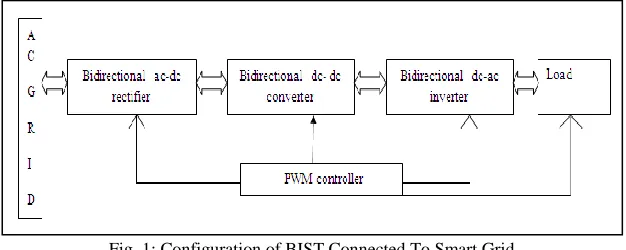
LOCK DIAGRAM REPRESENTATION OF GRID CONNECTED HYBRID SYSTEM WITH SMART GRIDIn Fig.2 shows the block diagram of representation grid connected hybrid system with smart grid [2] used for home load application. Home load has high peak demand (or) low demand variation. So excess power return to grid is needed. This home load application BIST used for the purpose bidirectional power flow [3] direction. It consists of ac-dc rectifier dc-dc converter dc-ac inverter. Battery used for additional source for emergency purpose.
Fig. 2: Block Diagram Representation of Grid Connected Hybrid System with Smart Grid Connected
IV.
I
NTELLIGENT SEMICONDUCTOR TRANSFORMERHigh-Voltage Part: A.
The circuit of ac-dc converter, which converts single-phase ac voltage of into rectified dc. The ac-dc converter has high-frequency transformers, which present high-high-frequency [10]-[12] resonance and input–output isolation. The input side works in high voltage, while the output side works in low voltage. Fig.3shows the high voltage part and low voltage part shows in Fig .6 The, the input side is considered with three half-bridge modules linked in series, in which two IGBT units are associated in series in the reverse direction. The output side is intended with three half-bridge modules linked in shunt. Total system operates in [11] bidirectional high-frequency resonance mode in a fixed frequency with 50% duty ratio to decrease system size and switching loss. The switching pulses for each switch in a single-module of the bidirectional high-frequency ac/dc converter according to the polarity of the ac input voltage. The gating pulses for each switch are generated with same pattern power flow in a module.
Mode of Operation: B.
Mode 1: 1)
The way of power flow is forward and the divide of input voltage is positive. In the first stage, the primary current flows through the transistor in M1 and the diode in M2 when M1 turns ON. Then secondary current flows through diode in M5. In the next position, the primary current allows through the transistor in M3and the diode in M4 when M3 turns ON. At this position, the secondary current flows through the diode in M6.
Mode 2: 2)
Fig. 3: Bidirectional Intelligent Semiconductor Transformer Mode 3:
3)
The direction of power flow is in the direction of the back and the division of input voltage is positive. In the first step, the secondary current flows throughout transistor inM5, when M5 is turn ON. At this illustration, the primary current flows through the diode in M1 and the transistor in M2.
Mode 4: 4)
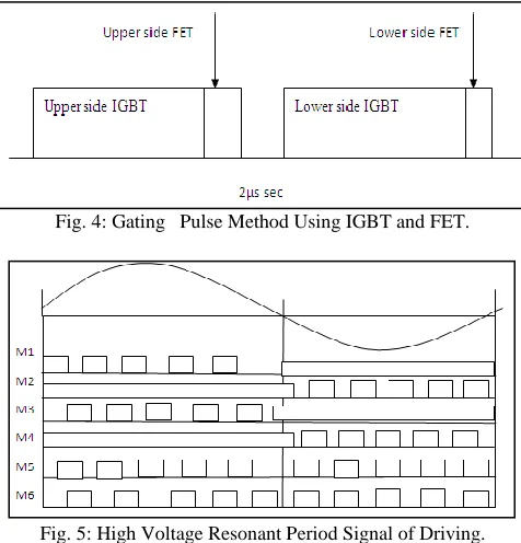
The way of power flow is in the direction of back and the divide of input voltage is negative. In the first step, the secondary current flows all the way through transistor in M6 when M6 turn ON. At this illustration, the primary current flows throughout the transistor in M1 and the diode inM2. In the next step, the secondary current flow through the transistor inM5whenM5 turns ON. At this example, the primary current flows all the way through the transistor inM3and the diode inM4 shows in fig.5.
Fig. 4: Gating Pulse Method Using IGBT and FET.
Fig. 5: High Voltage Resonant Period Signal of Driving.
Low-Voltage Part: C.
Fig. 6: Configuration of Inverter and Converter Topology
In regulate and to get better this switching loss a MOSFET is coupled in parallel to apply a hybrid switch. Shows Fig.4 supply the gating signal to the hybrid switch. The MOSFET turns ON only some microseconds and advance on while the IGBT switch turns OFF. After the MOSFET turns ON, the IGBT turns OFF directly and the MOSFET turns OFF the immediate that the IGBT is initially to turn OFF shows in fig.7.
Fig. 7: Controller Diagram of Bidirectional Dc-Ac Converter
Zero-Voltage-Switching (ZVS): D.
In the operation given that the magnetizing inductance Lm cannot have infinity value in real transformer, operational modes are rather different from. As have explained in fig.8 and it is supportive to achieve soft-switching of switch [13]. All mode in have similar ZVS operation so that operational mode study is explained based on mode 1 of forward power flow with positive input voltage.
Fig. 8: ZVS Operation Mode
Transformer Design: E.
The operational waveform of the LLC resonance converter [7]for the period of half of the line cycle. To examine the planned circuit, it is required to derive the resonant waveform expressions
The efficient resistor mode of secondary stage is only written as switch the output power of each resonant converter Po. Referring to the resonant current waveforms of both sides during nth switching period can be written as The primary resonant current L r phase a small delay to the secondary resonant current I L r s since of the magnetizing current
[ ] √ [ ] ( ) [ ] (4)
[ ]
(5)
Since vac1 and v L are understood to be constant during switching period, RMS current of I L r p and the delayed angle of every switching period can written as follows
[ ]
√
(6)
where Lm is the magnetizing inductance referred to the primaryside. The IGBT collector to emitter capacitance Cce varies according to the magnitude of collector to emitter over crowding voltage.
V.
S
IMULATION RESULTSThe simulations were performed and classify to test the HRES controlled by the application ANFIS controllers by comparing it by means of the HRES controlled by the classical EMS. They have two types.The initial one, Performed by the reproduction of the hybrid system operation during one year, was used to ensure the right presentation of the ANFIS-based supervisory control system in categorize to assure the power demanded by the grid.Anthoer one is short duration of dynamic performance. Fig.9 shows three ac voltage and current mesured from wind turbine. WT and PV power for the period of a week. The PV and WT DC-DC converters integrate a MPPT controller, so that the renewable energy sources are generating the maximum available power in all period .The wind speed and the sun-radiance used in the simulations were collected from a weather station located in Algeciras, Cadiz. The controls of PV and WT are considered independent of the supervisory control systems. Moreover, shows the maximum available power in the total hybrid system, and the power demanded by the grid for the time of the same period. The maximum available power is intended as the sum of the power generated by the renewable sources (WT and PV) and the maximum available power in the grid. Reminder that the power demanded by the grid is at all times less or equal than the maximum available power. Fig.10 shows the pv output voltage measured from pv array.. Fig.11 shows the wind and pv output voltage is variable one
Then excess power return to using Smart distribution system.This system combine with converter, inverter and rectifier.The load will not consumed this system will act as a source. PWM comtroller can generate gate pulse, power will be return to grid... Fig.12 shows the smart grid connected the load, using resistive will be connected 10 ohm.
Fig. 9: Simualation Diagram For Three Wind Output Voltage Measured For Wind Turbine.
Fig. 11: Simulation Diagrm Of Wind And Solar Output Voltage Connected To Grid By Using Luo Converter.
Fig. 12: Simulation Diagram Of Smart Grid Distuributon System Connected To Resistive Load.
VI.
C
ONCLUSIONThis paper analysed and discuss about an ANFIS-based EMS of a grid-connected hybrid system for smart grid which is composed of renewable energy sources (WT and PV panels). Then coordination with the EMS, the single-phase inverter is controlled by an PWM-based controller in order to regulate the power. ANFIS-based EMS achieves better results, since it presents higher hybrid system efficiencies, and it is capable of injecting more energy into grid than compare to the classical EMS. The results of both simulations and demonstrated that the proposed EMS allows a better control then the classical EMS and reliable operation in grid-connected application.The short scale operation shows the right dynamic response of the hybrid system and inverter against sudden power variations and its effect on the dc bus voltage and waveform of the inverter output voltage and current. In this case, the inverter controlled with ANFIS presents lower error indexes and THD than those obtained with the controllers. The operational feasibility of the transformer was verified by computer simulation.
R
EFERENCES[1] M. Jamil,B.Hussain, M.Abu-Sara, R.J.Boltryk, and S.M.Sharkh,“Microgrids power electronic converters: State of the art and futurechanges,” inProc. 44th Int. Universities Power Eng. Conf., 2009, pp.1–5.
[2] P. Siano, C. Cecati, H.luo Yu, and J. Kolbusz, “Real time operation of smart grids via FCN networks and optimal power flow, ”IEEE Trans.Ind. Inf., vol. 8, no. 4, pp. 944–952, Nov. 2012.
[3] S.Jiang,W. Wang, H.Jin and Xu,“Powermanagementstrategy for microgrid with energy storage system,” inProc. 37th Annu. Conf.IEEE Ind. Electron. Soc., pp. 1524–1529.
[4] L. Valverde, F. Rosa, and C. Bordons, “Design, planning and manage-ment of a hydrogen-based microgrid,”IEEE Trans. Ind. Inf., vol. 9, no.3, pp. 1398– 1404, Aug. 2013.
[5] M. P. Kazmierkowski, M. Jasinski, and G. Wrona, “DSP-based control of grid-connected power converters operating under grid distortions, ”IEEE Trans. Ind. Inf., vol. 7, no. 2, pp. 204–2011, May 2011.
[6] M. N. Marwali, J. W. Jung, and A. Keshena, “Control of distributed generation systems – Part II: Load sharing control,”IEEE Trans. Power Electronics., vol. 19, no. 6, pp. 1551–1561, Nov. 2004.
[7] M. Kang, P. Enjeti, and I. Pitel, “Analysis and design of electronic trans-formers for electric power distribution system,”IEEE Trans. Power Elec-tron., vol. 14, no. 6, pp. 1133–1141, Nov. 1999.
[8] S. N. Bhaskara and B. H. Chowdhury, “Microgrids – A review of mod-eling, control, protection, simulation and future potential,” inProc.IEEE Power and Energy Soc. Gen. Meeting, 2012, pp. 1–7.
[9] M. Arindam, S. Ashok, G. Mahesh, B. Simon, and D. Shoubhik, “Intel-ligent universal transformer design and applications,” in Proc. 20th Int.Conf. Exhib. Elect. Distrib., 2009, pp. 1–7.
[10] “Feasibility assessment for intelligent universal transformer,” EPRI, PaloAlto, CA, USA, EPRI Rep. TR-1001698, Dec. 2002.
[11] E. C. Aeloiza, P. N. Enjeti, L. A. Moran, and I. Pitel, “Next generation distribution transformer: To address power quality for critical loads,” inProc. IEEE Annu. Power Electron. Spec. Conf., 2003, pp. 1266–1271.
[12] Z. Tiefu, Z. Jie, S. Bhattachaya, M. E. Baran, and A. Q. Huang, “Anaverage model of solid state transformer for dynamic system simulation,”inProc. IEEE Power Energy Soc., 2009, pp. 1–8.