An Accelerated Hardware Software in The Loop
Technique for Control Units
Mossaad Ben Ayed
1, Faouzi Bouchhima
2, Lilia Zouari
3and Mohamed Abid
4National Engineering School of Sfax University of Sfax, Tunisia
1 [email protected], 2 [email protected], 3 [email protected], 4 [email protected]
Abstract— Due to the complexity and heterogeneity of
systems, design and verification environments are widely requested. Such systems combine into continuous and discrete models. The main problem is the difference of algorithms between continuous and discrete simulators. The industrial tool Matlab/Simulink is widely used in modeling systems. The main advantage of this tool is its ability to model in a common formalism the software and its physical environment. Unfortunately, Matlab/Simulink still suffers from many limits in modeling and verification. Due to the multidisciplinary nature of advanced systems and to overcome these limits in modeling and verification, several tools based on combined language are adopted. This paper describes a novel verification technique for
Control Units. A synchronization model between
Matlab/Simulink and a real board is presented. Three different applications are used to improve the important reduction of the time simulation.
Index Term-- HIL, Co-design, Simulator, Emulator,
Verification, Simulink.
I. INTRODUCTION
As the number and the complexity of mechatronics components increases, tools and technologies for developing and verification of the Control Units (CU) are required. Simulink presents the widely tool used for continuous/discrete systems and it is a good target for design and verification on the earlier stage of the design. Matlab/Simulink is not only used in all the steps of the cycle of development but also played a crucial role in the numerical simulation of CU. The cycle development based on Matlab/Simulink, especially in automotive industry, can be divided on three steps.
First, the Model In the Loop (MIL) [1] refers to the kind of testing performed to verify the expected performance and robustness of a control algorithm in model form in a closed loop environment. This step concerns the definition of a mathematical model of the plant and the control law. This model is validated using a numerical simulation.
Then, the Software In the Loop (SIL) [2] step concerns the implementation of the control algorithm in a low language such as C.
Finally, the Hardware In the Loop (HIL) [3] step concerns the compilation of the controller implementation into an executable running on a particular hardware.
HIL involves connecting the actual CU to the real time simulation models, in which the CU in hardware is integrated with virtual models of the devices and systems being controlled.
The goal of this paper is to investigate the needs and the possibilities concerning a combined usage of Matlab/Simulink and a real architecture based on co-design development, implemented in the board. A Hardware Software In the Loop is announced in this paper.
Section 2 presents the related works for design and verification method in Simulink. Section 3 presents the conventional approach and the synchronization scheme of the Hardware Software In the Loop technique. Section 4 describes the different steps for implementation and the experimental results. Section 5 concludes the paper with a discussion.
II. RELATED WORK
There are mainly tow ways in literature to combine Simulink with another environment.
A. Integration
There have been several studies regarding the integration of different environments and enabling different modeling frameworks to interact with each other. [4] is made to integrate SystemC in Matlab/Simulink environment using the S-function bloc. Support the different abstraction layers for embedded systems in Simulink environment is the aim of the last work.
The work [5] integrates the Processor Expert tool in Simulink to use different kinds of microcontroller. The integrated environment has to follow the Simulink solver. This fact is the major problem. Indeed, the discrete simulation progresses with the respect of the integration step imposed by the solver in the continuous simulation.
B. Co-simulation
The co-simulation methodology is based on different simulation tools running simultaneously and exchanging information in a collaborative manner for verification reasons.
We can cite especially Simulink/Modelsim,
Simulink/SystemC and HIL.
Simulink/Modelsim is adopted when the Hardware Description Language (HDL) is used to describe the behavior of the control algorithms. HDL Verifier automates verification by using Simulink to stimulate the HDL code and analyze its response [3].
integration at multiple abstraction layers, for systems containing both software and hardware components. As an example, CODIS (COntinuous DIscrete Simulation) [6] is a tool which can automatically produces co-simulation instances for continuous/discrete systems simulation using SystemC and Simulink simulators. This is done by generating and providing co-simulation interfaces and the co-simulation bus. To evaluate the performances of simulation models generated in CODIS, they measured the overhead given by the simulation interfaces [7].
Hardware In the Loop:
The more traditional application of the HIL concept is controller design and testing, in which a CU in hardware is integrated with virtual models of the devices and systems being controlled. Most famous techniques of HIL are MathWorks’ solution xPC Target [8] [9] and Real-Time Windows Target [10], where the model is executed on a dedicated system or on a windows system, respectively. The last consists of synchronizing the clocks of the virtual subsystems with the clocks of the real subsystems and achieving determinism in the overall system.
The HIL is adopted in verification and testing for many advantages:
Control and regulation functions can be tested in early stages of development, even before a test carrier.
Typical test drives under low conditions (ambient, snow, ice) can be performed repeatedly.
Failures and errors that could have devastating effects in a real system can be simulated and tested systematically.
The experiments performed in the HIL system can be reproduced precisely, and automatically repeated as often as required.
However, the modeling language provided and the different advantages of the HIL, these solutions have not been designed for hardware/software co-design purposes. There are several weaknesses that motivate us to develop a new standard target based on FPGA board [11].
Only few targets exist and therefore far from all CU families and derivates are supported.
Each CU target has its own block set. This fact prevents the reusability and the portability of the model using these HW specific blocks.
The way in which the peripheral HW is handled by the generated code is predefined by the target developers and it can not be changed by the user. Wiring harness HIL simulation platform needs to
be redone each time the hardware interface of a CU changes.
The next section presents the Hardware Software In the Loop (HSIL) as the proposed verification technique.
III. CONVENTIONAL APPROACH
Control embedded systems are mostly heterogeneous devices. Their design is based on hardware and software components. Each part needs to be aware of the characteristics of other parts, in order to provide optimized components. The best strategy adopted is co-design, since it allows us to develop HW/SW components concurrently. The main idea is to set the HSIL to overcome the limits of the HIL.
Our method described in the next section, improves the HIL, and has many advantages such:
Expand the HIL to attend the Co-design strategy. Use of one and same S-function for every CU. This
fact lets the reusability and the portability of the model. Able to verify multiple CU in the same system and to
modify one without modify the architecture. Figure 1 describes the global idea of HSIL.
Two issues are essential for the HSIL architecture: the communication and the synchronization models.
A. Communication model
Routine Number (RN)
Size (S)
Data (D)
Time stamp (TS)
Header Body
Fig. 1. Hardware Software In the Loop architecture
This communication is based on packets which are constructed by the communication interface using S-Function between Simulink and board. An S-Function is a computer language description of a Simulink block. It uses syntax of call allowing us to interact with Simulink solvers.
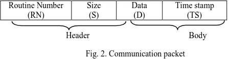
A Data packet, figure 2, is used to perform the synchronization scheme between the Simulink simulator and the emulator.
Fig. 2. Communication packet
Data packet comprises a header and the Body. The header contains the routine number and the data size. The routine number corresponds to the CU that will be executed in the target architecture. The body is composed with data and the time stamp to synchronize when it is necessary.
Note that any packet received by the board side generates an USB interruption that can be exploit in the implementation phase to interrupt the target processor each time a packet is received.
B. Synchronization model
Because the heterogeneity of systems, analog-digital (AD) and digital-analog (DA) converters are used. These converters are integrated in synchronization bloc (S-function), see figure 3.
Fig. 3. Synchronization bloc
The ADC is used to transform the analog input to digital signal based on equation (1).
) 1 ( 2
) ( ]
[k k XNt
X
Where:
X(t) = Analog input X[k] = Digital output code
N = Number of digital input bits (resolution) k{1,…..,N}
The DAC is used to transform the digital signal after the processing step to analog output based on the transfer function shown in (2).
) 2 ( ) ( 2
] [ )
(t Y k X t
Y N
Where:
Y(t) = Analog output Y[k] = Digital input code
N = Number of digital input bits (resolution) X(t) = Reference Value (full-scale )
A key issue of the proposed approach is the time synchronization between the Simulink simulator and the processor emulated on the FPGA board. The verification method is based on the following synchronization schemes which respect the interaction style that can be involved between continuous and discrete model, figure 4 and 5.
The Continuous model waits the end of the
hardware/software task.
When a hardware/software components is emulated by the board, the continuous model uses a waiting loop for data (see figure 4).
S-Function :
HSIL
Communication : USB link
FPGA board
SW Controller
Target Architecture Bus
Continuous model
Input Signal Output Signal
Discrete model
Y(t)
Synchronization (S-Function)
Digital processing
X(t) X[k] Y[k]
N N
Fig. 4: Sheme 1 of synchronization scheme for HSIL
Once controller task is finished, the emulator sends data to the simulator and a switch context from the board to Simulink simulator is taken. At this time, the continuous model receives data and resumes the execution. Note that the Simulink and the emulator need to usually exchange information about the time.
The next section drafts the implementation and her details.
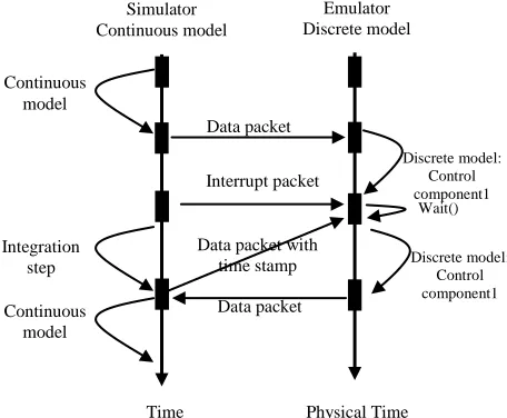
The Continuous model interrupts the
hardware/software task.
The second scheme (see figure 5) is lunched when the time simulation of discrete model is greater than the time of integration step. In this case, the emulator receives an interrupt from continuous simulator to make a switch context, and then it executes a wait function.
Fig. 5. Scheme 2 of synchronization scheme for HSIL
At this step, the discrete time simulator is not advanced and the simulator continuous advance with an integration step time. Then, the continuous simulator sends the time stamp for the discrete simulator to continue the simulation of control component.
IV. EXPERIMENTAL RESULTS
This section describes the three applications used for environment validation: DC Motor Speed Controller as basics applications, Closed-Loop Engine Speed Control as mechatronics applications and Control of a robot arm as robotics applications. The first part of this section presents the different applications and the implementation steps made. The second part discusses the obtained results.
A. Description and implementation
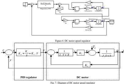
1st Application: DC Motor Speed Controller
The first application example, figure 6, consists in a DC Motor Speed Modeling in Simulink with a PID regulator. The following equation (3) in open-loop transfer function is:
) 3 ( sec / )
)( ( ) (
) ( )
( 2
V rad K
R Ls b Js
K s
V s s P
Where:
The rotational speed is considered the output and the armature voltage is considered the input.
(J) moment of inertia of the rotor (b) motor viscous friction constant (Ke) electromotive force constant (Kt) motor torque constant (R) electric resistance (L) electric inductance
Then, a PID regulator is added to control the DC motor speed. Figure 7 shows the diagram of the global system.
Continuous model
Discrete model: Control component
Simulator Continuous model
Emulator Discrete model
Data packet
Data packet
Time Physical Time
Continuous model
Discrete model: Control component1
Simulator Continuous model
Emulator Discrete model
Data packet
Interrupt packet
Time Physical Time
Wait()
Integration step
Data packet with
time stamp Discrete model: Control
component1
Data packet Continuous
d/dt(i ) i d/dt(theta) d2/dt2(theta) 0.1 dampi ng V Sum1 Sum Scope
Kd.s +Kp.s+Ki2 s Régul ateur PID
1 Resi stance -K-Kt -K-Ke 1 s Integrator1 1 s Integrator -K-Inerti a -K-Inductance
Figure 6: DC motor speed regulator
Fig. 7. Diagram of DC motor speed regulator
2nd Application: Closed-Loop Engine Speed Control
This example shows how to model a four-cylinder spark ignition internal combustion engine from the throttle to the crankshaft output. We used well-defined physical principles supplemented, where appropriate, with empirical relationships that describe the system's dynamic behavior without introducing unnecessary complexity.
This example describes the concepts and details surrounding the creation of engine models with emphasis on important Simulink modeling techniques. The basic model uses the enhanced capabilities of Simulink to capture
time-based events with high fidelity. Within this simulation, a triggered subsystem models the transfer of the air-fuel mixture from the intake manifold to the cylinders via discrete valve events. This takes place concurrently with the continuous-time processes of intake flow, torque generation and acceleration. A second model adds an additional triggered subsystem that provides closed-loop engine speed control via a throttle actuator. These models can be used as standalone engine simulations [15].
Figure 8 shows the different elements of the engine model.
Closed-Loop Engine Speed Control
Copyright 1990-2005 The MathWorks Inc.
1 crank speed (rad/sec) N edge180 valve timing
throttle deg (purple) load torque Nm (yellow) 30/pi rad/s to rpm Load drag torque Teng Tload N Vehicle Dynamics Throttle Ang.
Engine Speed, N
trigger
mass(k+1)
Throttle & Manifold Speed Setpoint ? Engine Speed (rpm) Desired rpm N Throttle Ang. Controller mass(k+1) mass(k) trigger Compression Air Charge N Torque Combustion Engine Speed Throttle Degrees
Fig. 8. DC motor speed regulator
R S
L.
1
t
K + - - + S K S K K d i p . - + L
T
Ta
i
e KV
e
r
y
y
DC motor PID regulator b S J. Throttle
The first element of the model is the throttle body. The control input is the angle of the throttle plate. The rate at which the model introduces air into the intake manifold can be expressed as the product of two functions: (1) an empirical function of the throttle plate angle only (2) a function of the atmospheric and manifold pressures.
Intake Manifold
The simulation models the intake manifold as a differential equation for the manifold pressure. The difference in the incoming and outgoing mass flow rates represents the net rate of change of air mass with respect to time. This quantity, according to the ideal gas law, is proportional to the time derivative of the manifold pressure.
Intake Mass Flow Rate
The mass flow rate of air that the model pumps into the cylinders from the manifold is described by an empirically derived equation. This mass rate is a function of the manifold pressure and the engine speed.
Compression Stroke
In an inline four-cylinder four-stroke engine, 180 degrees of crankshaft revolution separate the ignition of each successive cylinder. This results in each cylinder firing on every other crank revolution. In this model, the intake, compression, combustion, and exhaust strokes occur simultaneously (at any given time, one cylinder is in each phase). To account for compression, the combustion of each intake charge is delayed
by 180 degrees of crank rotation from the end of the intake stroke.
Torque Generation and Acceleration
The final element of the simulation describes the torque developed by the engine. An empirical relationship dependent upon the mass of the air charge, the air/fuel mixture ratio, the spark advance, and the engine speed is used for the torque computation.
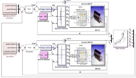
3rd Application: Control of a robot arm
The robotic application, especially robot arm [25] [26], is widely used in many fields. This example presents the control of robot arm with a variable speed based on the brushless DC machines [24]. The last few years, the brushless DC machines (BDCM) marks several advantages like robustness, reliability and simplicity of its implementations [16], [17], [18], [19]. Currently, an increasing attention is given to improve the cost-effectiveness and the compactness of the machine drives representing the actuators of the robot arm as well as the reduction of the execution time of the control algorithm which represent crucial cost benefits especially for robotic applications. A conventional inverter topology so-called “Six-Switch Three-Phase Inverter (SSTPI)” is used for robot arm. It ensures the correct switching to obtain the appropriate voltages should be applied to the motor windings. All the parts of robot arm are described in figure 9.
Fig. 9. Block diagram of the control strategy implemented in the SSTPI-fed BDCM drive
BDCM
The Brushless Direct Current motor BDCM is a three phase synchronous motor. This motor is a brushless DC which is
composed of an inner stator and an external permanent magnet rotor.
L
E
V
I
L
R
dt
dI
(4)Then, the mechanical equation of Brushless DC motor is given by the following expression:
m m em m m m
J
C
C
J
f
dt
d
(5)
Where :
• Cem and Cm are the Electromagnetic and load torque of the motor respectively,
• f represents the friction, • Jm is the inertia of the motor, • Ωm is the velocity of the motor, • E is the electromotive force,
• I is the current in the phases of motor, • V is the tension in the phases of motor, • L is the inductance of the motor, • R is the resistance of the motor. with, E = KEΩm and Cem = KtI. • KE et Kt are constants,
Inverter
After multiplying the current references by their amplitudes, the error between them and the currents flowing in the motor phases is applied to hysteresis regulators whose output gives us the control signals of the IGBTs of the inverter to obtain the adequate voltages that should be applied to the Brushless DC motor.
Hysteresis Controller
Each leg of the inverter includes the third of the battery pack in series with a set made up of an IGBT and an antiparallel-connected diode [20]. The outputs of the hysteresis current controller determine the control signals for the IGBTs. Indeed, the principle of the hysteresis control is to maintain the measured current within a band of centered given width around the reference current Iref.
Torque Controller
The control strategy considered in the case of a conventional six-switch three-phase inverter in the armature, the proposed control scheme includes a torque loop, thanks to which, the high torque ripples during sequence-to-sequence commutations have been reduced. These are due to the commutations of the BLDCM power supply from 1/3 to 2/3 (and vice-versa) of the battery pack [21].
Current reference
In the case where the machine generates trapezoidal back EMFs, it should be fed by 120 electrical-degree rectangular currents in order to achieve high torque with reduced ripples.
It is to be noted that the operation of the BLDCM can be divided into six different operating sequences with in each just two phases are fed.
PID Controller
When the system presents a linear behavior, the regulation of the movement can be achieved by conventional techniques control. We can note in this case the decentralized control type PID. This technique is widely used by robot manipulators using gear motors with high reduction ratios. Therefore, each joint is controlled by PID control with constant gains, due to the facility of its implementation and low cost [22], [23].
Taking into account that, in this work we dispose of an association of a robot arm-brushless DC motor associated with its high reduction ratio, we are interested in the implementation of the control type PID.
The aim as mentioned bellow is to verify the controller units and to accelerate the time simulation of the whole system. For the first application, the model has two integrators and one PID that will be considered as SW applications. For the second, the controller and the compression are considered as control units. For the third example, the speed controller, the torque controller and the current hysteresis controllers present the control units. Three steps are essential for the implementation.
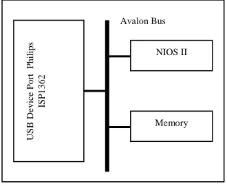
Fig. 10. Architecture target
Step 1: Target architecture
The verification idea is based on combined tools to satisfy continuous and discrete models. For the discrete model an FPGA type ALTERA DE2-70 is used as a board and QuartusII, NIOSII IDE as tools. The first step is to set the architecture model. Figure 10 shows the architecture chosen. It
contains the NIOSII processor [13], Avalon bus, memory and the ISP1362 USB controller [14]. The control units are considered as SW applications that will be executed in the last architecture.
USB
De
vice
P
or
t
P
hil
ips
IS
P
1
362
NIOS II
Step 2: Integration of synchronization bloc
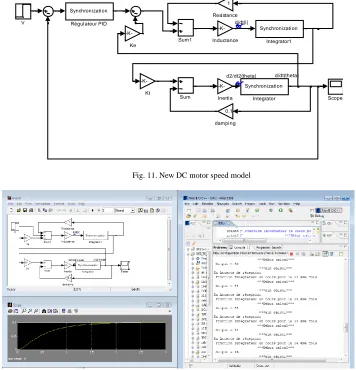
A C++ S-function bloc is used to implement the synchronization scheme between Simulink simulator and the target architecture in the FPGA board, figure 11.
The Synchronization bloc is an interface that creates break points which must be reached accurately by a solver. These points are the time stamps of the input signal from continuous model. When a signal is received, this interface blocks the solver and makes a switch context to the board. At first, the last activates the USB link with interruption mode and sends the data packet. After resuming execution the interface Synchronization sets the next activation time.
Step 3 : Simulation results
The simulation was performed using the synchronization scheme, since the continuous model generates state events and the signals update events are not periodic.
1st Application: DC Motor Speed Controller
At first, the new DC motor speed scheme, figure 9, is described using the following parameter: J=0.01; b=0.1; K=0.01; R=1; L=0.5.
Figure 12 shows the whole operation between Simulink and the NIOSII IDE environment.
d/dt(i)
d/dt(theta) d2/dt2(theta)
0.1
damping V
Sum1
Sum Scope
Synchronization
Régulateur PID
1
Resistance
-K-Kt
-K-Ke
Synchronization
Integrator1
Synchronization
Integrator
-K-Inertia
-K-Inductance
Fig. 11. New DC motor speed model
Fig. 12. Simulink/NIOSII simulation/emulation
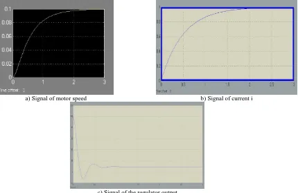
To verify the efficiency of the synchronization model, three figures issued by each synchronization bloc are used as shown in figure 13.
a) Signal of motor speed b) Signal of current i
c) Signal of the regulator output
Fig. 13. critical signal
2nd Application: Closed-Loop Engine Speed Control
The novel scheme of the closed-loop engine speed control, figure 14, is described using synchronization bloc.
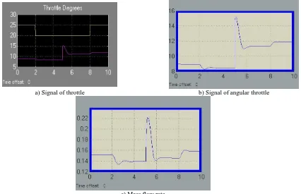
To validate the Hardware Software In the Loop technique, three figures that describe the throttle, the angular throttle and
the mass flow rate issued by the model, are used as shown in figure 15. The simulation time is 2 second calculated by the simulator.
Closed-Loop Engine Speed Control
Copyright 1990-2005 The MathWorks Inc.
1 crank speed
(rad/sec)
N edge180
valve timing
throttle deg (purple) load torque Nm (yellow) 30/pi
rad/s to rpm
Load
drag torque synchronization
controller Teng
Tload N
Vehicle Dynamics
Throttle Ang.
Engine Speed, N
trigger
mass(k+1)
Throttle & Manifold Speed
Setpoint ?
Engine Speed (rpm) synchronization1
Compression
Air Charge
N Torque
Combustion
Engine Speed
Throttle Degrees
a) Signal of throttle b) Signal of angular throttle
c) Mass flow rate
Fig. 15. critical signal for closed-loop engine speed control
3rd Application: Control of a robot arm
Figure 16 shows the implementation of the HSIL technique for the control of a robot arm application. PID
controller, torque controller and hysteresis controller are replaced with synchronization blocs.
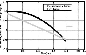
The results of simulation areperformed in figure 17.
0 0,02 0,06 0,1 0,14 0,18 0,2 -0.1 -0.05 0 0.05 0.1 0.15 Time(sec) E le c tr o m a g n e ti c a n d L o a d T o rq u e s (N .m ) Electromagnetic Torque Load Torque
a) Responce of electromagnetic and load torques
0 0,02 0,06 0,1 0,14 0,18 0,2
-100 0 100 200 300 400 500 Time(sec) R e fe re n c e a n d M o to r S p e e d s ( tr /m in
) Reference Speed
Motor Speed
b) Reference and motor speed
0 0,05 0,08 0,11 0,14 0,2
-0.02 0 0.02 0.04 0.06 0.08 0.1 0.12 Time(sec) P o s it io n ( ra d )
c) Robot angulaire position
Fig. 17. Signal response of robot arm system
The aim of HSIL is to decrease the simulation time. For this reasons, table 1 shows the different time simulation of each part of robt arm described bellow.
Table I different simulation time
Parts Simulation time (s)
BDCM 351
Inverter 723
Hysterisis controller 41
Torque controller 14
Current reference 48
PID controller 16
All system 1193
B. Results and discussion
The last section improve the correcteness of the result using the HSIL thechnics. In this part we are interesting to compare the simulation time using Matlab/Simulink only and Matlab/Simulink with the use of the Hardware Software In the Loop. Table 2 shows the different results. The HSIL technique reduce the time simulation by six times.
Simulation method \ Application DC Motor Speed Controller Closed-Loop Engine Speed Control Control of a robot arm
Simulation with Matlab (s)
3 12 7523
Simulation using HSIL (s)
1 2 1193
V. CONCLUSION
not only the HW/SW design in CU but also ensure the reusability and the portability of CU. Two applications are
used to evaluate the proposed technique.
Simulation/emulation results shows that the simulation time is reduced with comparison of the SIL technique based on simulation only.
REFERENCES
[1] Melih Çakmakc, Yonghua Li and Shuzhen Liu.”Model-in-the-Loop
Development for Fuel Cell Vehicle”, 2011 American Control Conference on O'Farrell Street, San Francisco, CA, USA June 29 - July 01, 2011
[2] Vitalijs Osadcuks, Ainars Galins. “Software In the Loop simulation of
autonomous hybrid power system of an agricultural facility”, Engineering for rural development, Jelgava, 24.-25.05.2012. p 500-505
[3] M. Bacic, “On hardware-in-the-loop simulation,” in 44th IEEE
Conference on Decision and Control, 2005 and 2005 European Control Conference. CDC-ECC’05, 2005, pp. 3194–3198
[4] Walid Hassairi, Moncef Bousselmi, Mohamed Abid and Carlos
Valderrama, “Matlab/SystemC for the New Co-Simulation
Environment by JPEG Algorithm” , MATLAB – A Fundamental Tool for Scientific Computing and Engineering Applications – Volume 2, p 120-138.2012
[5] Roman Bartosinski, Zdeněk. Hanzálek, Petr Stružka, and Libor
Waszniowski, “Integrated Environment for Embedded Control Systems Design”, Parallel and Distributed Processing Symposium, 2007. IPDPS 2007. IEEE International
[6] F. Bouchhima, M. Brière, G. Nicolescu, M. Abid, E. M.
Aboulhamid, “A SystemC/Simulink Co-Simulation Framework for Continuous/Discrete-Events Simulation”, Behavioral Modeling and Simulation Workshop, Proceedings of the 2006 IEEE International
[7] Dogan Fennibay_y, Arda Yurdakuly and Alper Seny, “Introducing
Hardware-in-Loop Concept to the Hardware/Software Co-design of Real-time Embedded Systems”, The 7th IEEE International Conference on Embedded Software and Systems, ICESS 2010.
[8] MathWorks. (2013) xpc target. [Online]. Available:
http://www.mathworks.com/products/xpctarget/
[9] Hosam K. Fathy, Zoran S. Filipi, Jonathan Hagena and Jeffrey L.
Stein , “Review of Hardware-in-the-Loop Simulation and Its Prospects in the Automotive Area” , Modeling and Simulation for Military Applications, edited by Kevin Schum, Alex F. Sisti Proc. of SPIE Vol. 6228, 62280E, (2006).
[10] MathWorks. (2013) Real-time windows target. [Online]. Available:
http://www.mathworks.com/products/rtwt/
[11] Roman Bartosinski, Zdeněk. Hanzálek, Petr Stružka, and Libor
Waszniowski, “Integrated Environment for Embedded Control Systems Design”, Parallel and Distributed Processing Symposium, 2007. IPDPS 2007. IEEE International, p 1-8
[12] Soha Hassoun, Murali Kudlugi, Duaine Pryor, and Charles Selvidge,
“A Transaction-Based Unified Architecture for Simulation and Emulation”, IEEE transactions on very large scale integration (VLSI) systems, vol. 13, no 2, 2005.
[13] NIOS II Processor Reference. (2013) [Online]. Available:
http://www.altera.com
[14] ISP1362 Single-chip Universal Serial Bus On-The-Go controller.
(2013) [Online]. Available: http://www.cs.columbia.edu
[15] MathWorks. (2013) “Closed-Loop Engine Speed Control. [Online].
Available: http://www.mathworks.com
[16] L. Bai, “Electric Drive System with BLDC Motor,” Proc. IEEE
International Conference on Electric Information and Control Engineering (ICEICE), 2011.
[17] D.S. Sun, X. Cheng and X.Q. Xia,“Research of Novel Modeling and
Simulation Approach of Brushless DC Motor Control System,” Proc. IEEE International Conference on Product Service and
E-Entertainment (ICEEE), 2010.
[18] Ji.Hua and Li.Zhiyong “Simulation of Sensorless Permanent Magnetic
Brushless DC Motor Control System,” Proceedings of the IEEE International Conference on Automation and Logistics,Qingdao, China, September 2008.
[19] B.K. Lee and M. Ehsani, “Advanced BLDC motor drive for low cost
and high performance propulsion system in electric and hybrid vehicles,” IEEE International Electric Machines and Drives Conference (IEMDC’2001), Cambridge, Massachusetts, USA, 2001.
[20] Lilia Zouari, Asma Ben Rhouma and Mohamed Abid , ” On the
Potentialities of Reduced Structure Inverter Integrated in Robot Application ” , Proceedings of theWorld Congress on Engineering 2012 Vol II(WCE 2012), July 4 - 6, 2012, London, U.K
[21] A. Elantably, A. Ben Rhouma, A. Masmoudi and A.G. Holmes,
“Control device for driving a brushless DC motor,” US Patent 7643733, 2010.
[22] L. Adouane, “Modelisation and control of robots,” Note of course for
Electrical Engineer: Polytech Clermont Ferand, 2010.
[23] K. Khial, “Position control of a Servo System Including a Harmonic
Gear with torque measurement and compensation of Non-Linearity,” Project Graduation in Applied Sciences, Polytechnic school of Montreal. Department of Electrical Engineering and Computer Engineering Automation Section, 2001.
[24] Lilia Zouari, Asma Ben Rhouma and Mohamed Abid, “ On the
potentialities of reduced structure inverter integrated in robot application”, Proceedings of the world congress on engineering 2012, WCE 2012, London, U.K.
[25] M. Sayahkarajy, Z. Mohamed, “Mixed Sensitivity H2/H∞ Control of a
Flexible-Link Robotic Arm”, International Journal of Mechanical & Mechatronics Engineering IJMME-IJENS Vol:14 No:01, 2014.
[26] Khairunizam WAN, Rudzuan M. Nor, M. Nasir Ayob, D. Hazry,