STRUCTURE
DIPESH MAJUMDAR,
Department of Construction Engineering, Jadavpur University, Kolkata, India [email protected]
Abstract : One godwon structure of Kolkata was severely damaged due to fire. This structure had two parts one part was constructed with steel members and another was a RCC structure. Steel structure was completely damaged fire wherear RCC structure was partially damaged. Cover concrete of beams and columns is badly damaged in many places. Overall thorough visual survey with conducting NDT was done to assess the damages of the structure. Proper rehabilitation technique was applied to restore the structure.
Keywords : Repair, Concrete Column-Beam Jacketing
(1) Introduction
The godown structure of Ravi Bhansali & Mahesh Kr. Khemka consists of two parts. One part was constructed steel truss and steel column. Steel truss portion was three storied. Other portion is RCC framed structure, which is three storied. RCC framed structure is constructed with RCC columns placed in two rows. Columns are connected by RCC beams at every floor level. External wall is constructed with brick masonry wall. Severe fire broke out on the month of February, 2016. Steel truss portion of three storied godown is completely damaged, that portion is to be reconstructed completely. Three storied RCC portion is thoroughly inspected and tested to assess the existing condition of the building observations are described below.
(2) Nature of Distress of the structure
Damage on the superstructure due to fire is not so severe in ground floor. Some portion of plaster is partially damaged. Some cracks are noticed on the plaster at soffit level of ground floor roof slab.
Major damage is noticed at 1st floor level. Plasters are delaminated from soffit level of 1st floor roof slab (Plate No. 2). Alligator type cracks are noticed at soffit level of slab. Major parts of wall plaster have delaminated from existing wall due to fire. Some moderate level cracks are noticed at exposed concrete surface also. Colours of concrete is changed due to high temperature exposure. Doors and windows are completely damaged due to fire. No permanent geometric deformation is noticed on the RCC structural members. Exposed surface of concrete has shown “Dusty” feeling during touching with fingers. 2nd floor is equally damaged as 1st floor. Condition of roof is poor. Moderate cracks are noticed on the soffit level of roof. Seepage is also noticed wall plaster is cracked and delaminated from existing surface.
Plate No. 2 : Internal view showing delamination of plaster.
Plate No. 3 : Condition of brick masonry wall.
(3) Problems to be solved with this structure
Based on the investigations carried out, the following can be concluded.
• Detailed photographs of the structure, depicting the present condition of the structure, are documented for future reference.
• From thorough visual inspection and Non-destructive testing, it is clear that the structure is damaged by fire exposure.
• Ultrasonic Pulse Velocity results are noticeably low, may be due to generation of micro-cracks inside concrete members due high temperature exposure of concrete members. No permanent geometric deformation is noticed at any structural members.
• Plasters are delaminated at various places at 1st and 2nd floor.
• Core test results of slab concrete are showing strength above M-20 grade concrete. • Cracks are noticed on concrete surface in some places.
• Steel structure is to be reconstructed with proper drawing and design.
(4) Repair and rehabilitation strategy of the structure
Although the structure is damaged due to fire exposure, it is to be retrofitted. Detailed engineering methodology for column and beam jacketing, slab strengthening etc. to retrofit the structure is described below.
4.1 Jacketing methodology for RCC columns and beams
First of all, minimum 10 nos. MS pipe (50NB) prop with all proper attachment are to be used to support adjacent area of particular column to be repaired. During propping full contact between existing beam bottom and prop top is to be ensured.
existing column surface.
• Staging with necessary platform to facilitate work adjacent to distressed portion shall be done.
• The Damaged /loose concrete should be removed carefully by chisel and hammer or by breaker (Direct hammering should be avoided).
• Cleaning the surfaces by use of high pressure water blower & removal of loose adhering materials. • The existing surface should be cleaned by gentle hammering, if flakes are observed and by wire brushing
only.
4.3 Some cracks are noticed on beams and columns, those are to be sealed with epoxy grout. Repair Methodology for Stitching of Cracks and Sealing of Cracks.
• Groove cutting all along the line of cracks, cleaning the same by use of high pressure water blower and removal of loose adhering materials.
• Drilling the holes by use of drill machine, fixing the 12.5 mm dia G.I nozzles/ PVC nozzle with epoxy patching mortar along the crack area.
• Sealing the groove with 2 comp. epoxy patching mortar.
• Providing and grouting “Epoxy based, flowable, High early Strength, two stage expanding Grout” through prefixed PVC nozzle/GI nozzle with proper consistency. The minimum pressure for grouting shall be 2.0kg/cm².
• After grouting work, removal off the nozzles, sealing the same with 2 comp. epoxy patching mortar.
4.4 Repair Methodology for application of Polymer Modified Mortar on some portion of beam column and slab, where distress is minor.
• Removal of loose concrete and cleaning of surfaces as per procedure outlined in earlier clause
• Providing & applying one coat of polymer bonding coat in proportion 1:0.5 (i.e. polymer : Cement by wt.) over cleaned concrete surface etc. complete.
• Providing & applying single component, fibre reinforced high performance polymer modified mortar on cleaned concrete surface of wall, bottom slab and other surfaces. The mortar shall develop compressive strength up to 20 MPa in 3 days.
4.5 Repair Methodology for cleaning and removing corrosion from corroded rebar.
• The existing exposed reinforcements should be cleaned by gentle hammering, if flakes are observed and by wire brushing only.
• Exposed reinforcements are to be cleaned and rust to be removed by use of “Corrosion Removing Gel ”.
4.6 All columns and beams are to be jacketed with free flowing micro-concrete system.
Fig. No. 1 : Excavation Plan is shown at initial stage.
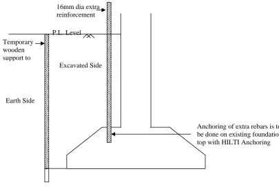
• During Jacketing of existing RCC columns extra reinforcement is to be provided externally. Anchoring of vertical reinforcement (16 mm dia) is to be done on existing top of RCC foundations.
Fig. No. 2 : After completion of excavation near existing column. 08 (eight) nos. 16mm dia rebar is to be are honed in existing top of foundation.
Temporary wooden support to
16mm dia extra reinforcement
P.L. Level
Earth Side
Excavated Side
Anchoring of extra rebars is to be done on existing foundation top with HILTI Anchoring External Brick
Existing Column External Brick
Excavation Line Inner part of
Outer part of
Fig. No. 3 : Plan drawing showing anchoring arrangement of 16mm dia rebars and fixing details of stirrup reinforcement.
• Existing RCC slab of 1st floor and 2nd floor is to be punctured to accommodate vertical extension of vertical reinforcement into next floor level as per following Fig. no. 4.
Fig. No. 4 : Top of first floor slab showing arrangement for extension arrangement of longitudinal reinforcement through minor dismantling of first floor slab only.
4.7 Repair Methodology for Jacketing with Free-flowing Low-shrinkage Micro-concrete.
• Providing and fixing in position ply postbox type formwork as per the site requirement.
• Application of Acrylic Polymer based bonding agents to ensure proper bond between old and new concrete.
• “A Dual Shrinkage-compensating, high flow, high strength ready to use micro concrete” should be poured in the formwork to patch the damaged concrete surface
• The same should be finished in line and level with the existing finish of the RCC member. • It should be cured for 3 days with water.
Existing Brick Work
Longitudinal reinforcement
Total 7 nos. 16 mm dia Anchored rebars onexisting foundation top with epoxy anchoring agent
Stirrup details
• Existing beams are moderately damaged due to fire exposure. Existing RCC beams are to be strengthened by jacketing methods. During jacketing of RCC columns three nos. of dowel reinforcement are to be left for beam jacketing as per Fig. no. 5
Fig. No. 5 : Sketch showing reinforcement arrangement of vertical column reinforcement. Connection between beam and column reinforcement is also shown.
Beams are to be jacketed with micro-concrete. At first shear reinforcements are to be anchored in existing roof slab with HILTI chemical anchor system as per Fig. No. 6. Then main longitudinal reinforcements are to be fixed as per Fig. No. 7. Finally micro concreting is to be done with Pre Packed Micro- Concrete system.
‘L’ shaped connecting reinforcement between column and beam reinforcement. Longitudinal reinforcement
A
A
Detail ‘A’
‘L’ shaped beam
reinforcement to be anchored with column and beam bottom reinforcement.
Fig. No. 6 : Sketch showing fixing arrangement of new stirrup to strengthen existing RCC beams.
Fig. No. 7 : Sketch showing fixing arrangement of new longitudinal reinforcement and shuttering arrangement for concreting.
• Existing slab is to be strengthened with overlaying concrete jacketing on top of the slab as per Fig. No. 8. Shear connector with 10mm dia rebars is to be provided on top of the RCC slab @ 4 nos. per sqm. Area. Thickness of overlaying concrete will be 65mm. Reinforcement bar details is to be followed as per Fig. no. 8.
Fig. No. 8 : Sketch showing strengthening arrangement of new stirrup to strengthen existing RCC beams. 65mm concrete with 10mm
down coarse aggregate Shear connector with 10mm dia rebars and HILTI anchor fasteners
8mm dia @ 200 C/C
12mm dia “U” bar is to be fixed 175mm c/c with HILTI chemical anchoring agent Existing Beam
Sectional view showing fixing plan of extra shear reinforcement with existing slab.
16mm dia is to be placed as longitudinal reinforcement.
Micro-concrete
Concreting is to be done through this zone
Reference
[1] Jirsa, J.O., “Behavior Of Epoxy-Grouted Dowels And Bolts Used For Repair Or Strengthening Of R.C. Structures, “Proceedings,
9wcee.
[2] Aci Committee 318, “Building Code Requirements For Reinforced Concrete,” Aci 318-83, American Concrete Institute, 1983.
[3] Luke, Philip C.C., Chon, Carlos, Jirsa, J.O., “Use Of Epoxies For Grouting Reinforcing Bar Dowels In Concrete, “Pmfsel Report 85-2,
Ferguson Structural Engineering Laboratory, University Of Texas At Austin, September 1985.
[4] H. J. Degenkolb Associates, “Connections To Existing Concrete For Seismic Rehabilitation,” To Be Published In 1988.
[5] Bass, Robert A, Corrasquillo, Ramon L, Jirsa, J.O., “Interface Shear Capacity Of Concrete Surfaces Used In Strengthening Structures,
“Pmfsel Report 85-4, December 1985.
[6] Winer, David F, “Behavior Of Steel To Concrete Connections Used To Strengthen Existing Structures, M.S. Thesis, University Of
Texas At Austin, August 1985.
[7] S.M. Alcocer, Head Of The Seismic Testing Area, National Center For Disaster Prevention; Associate Professor, Institute Of