MULTIRESOLUTION MOMENT
METHOD BASED ON THE IMPEDANCE
OPERATOR FOR THE ANALYSIS OF
PLANAR MICROSTRIP STRUCTURES.
NEJLA OUESLATI
SysCom laboratory, Electronic Engineer Department, National Engineer School of Tunis, Tunisia, Address, B.P. 37 Le Blevedere, 1002 Tunis, TUNISIA
TAOUFIK AGUILI
SysCom laboratory, Electronic Engineer Department, National Engineer School of Tunis, Tunisia, Address, B.P. 37 Le Blevedere, 1002 Tunis, TUNISIA
Abstract :
This paper presents an integral equation analysis of planar microstrip circuits. In the developed approach, the Moment Method (MoM) with wavelet expansion is combined to the generalized equivalent circuit (GEC) to characterize microstrip structures. The interest of the (GEC) method is to simplify the implementation of the moment method by the translation of an electromagnetic problem to an electric one with the use of the impedance operator. In the multiresolution moment method (MRMoM-GEC), an excitation on the plane of the circuit is used in conjunction with compactly supported wavelets trial functions. This approach generates a sparse linear system. The application of the Discrete Wavelet Transform (DWT), especially for large structures, allows a significant reduction of the unit time of central processing.
Keywords: Microstrip circuits; moment method; wavelet expansion; generalized equivalent method modeling.
1. Introduction
The integral equation technique is one of the oldest rigorous approaches for the numerical solution of electromagnetic problems [1]. The numerical solution of the integral equations encountered in electromagnetic problems is usually achieved through the use of the moment method (MoM) [2]. For small to medium scale problems with reasonable matrix sizes, this method offers a straightforward and efficient numerical solution. The difficulty arises when the complexity of the geometry and subsequently the number of unknowns increases resulting in very large matrices. The bottleneck is that all conventional types of basis functions traditionally used in the moment method generate full moment matrices.
In the beginning of the present decade, it was discovered that the wavelet expansion of certain types of integral operators generates highly sparse linear systems [3].
It was established in effect that the traditional drawback of the method of moment in view of fullness of resulting matrices is not an inherent feature of this technique, but it is a direct consequence of the type of basis functions used for the discretization of the underlying integral operators.
It can be concluded that the applicability of the moment method for the study of planar structures is contingent upon developing tools for effective reduction of the size of moment matrices. This goal may be achieved in two steps:
orthonormal wavelets. In the suggested approach, the unknown current or response is expressed as a twofold summation of shifted and dilated forms of a properly chosen basis function, which is often referred to as the mother wavelet.
This approach leads to the generation of highly sparse moment matrices [6-7].
2. Studied Structure
Microstrip lines are characterized by their compatibility with others passive or active microstrip structures. They are used in various applications such as the realization of the couplers, filters…
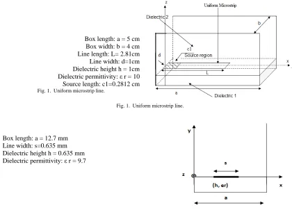
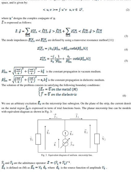
To highlight the adopted approach, we studied two structures as shown in Fig. 1and Fig. 2: an excited microstrip line by a voltage source to calculate its physical characteristic s, and an infinite transmission line to trace the dispersion curve of its fundamental mode.
Box length: a = 5 cm Box width: b = 4 cm Line length: L= 2.81cm
Line width: d=1cm Dielectric height h = 1cm Dielectric permittivity: ε r = 10 Source length: c1=0.2812 cm
Fig. 1. Uniform microstrip line.
Fig. 1. Uniform microstrip line.
Box length: a = 12.7 mm Line width: s=0.635 mm Dielectric height h = 0.635 mm Dielectric permittivity: ε r = 9.7
Fig. 2. Infinite laterally shielded microstrip line.
3. Theoretical Development
3.1. Generalized equivalent circuit modeling (GEC)
The concept of generalized equivalent circuits is based on the representation of the integral equations by an equivalent circuit in order to alleviate the resolution of Maxwell's equations [8]. This electromagnetic representation made it possible to extend the Kirchhoff laws generally employed with the (V-I) concept to the Maxwell formalism (E-H).
The generalized test functions which describe the electromagnetic state on the discontinuity interface are modeled by an adjustable virtual source not storing energy. The environment of the studied structure is expressed by an admittance (or an impedance) operator.
To explain the development of the theoretical formulation, we detail the theoretical GEC formulation of the first structure.
On the plane of the circuit, the electric tangential field is related to the total current density by the impedance operator:
(1)
is a projection operator on the and waveguide modal basis of the empty waveguide [9-10]. This basis is determined as a function of the waveguide type. The scalar product is defined on the Hilbert space, and is given by:
,
(2)where designs the complex conjugate of . is expressed as follows:
(3)
The mode impedances and are defined by using a transverse resonance method [11]:
(4)
(5)
is the constant propagation in vacuum medium.
is the constant propagation in dielectric medium.
The solution of the problem consists in satisfying the following boundary conditions:
(6)
We use an arbitrary excitation on the microstrip line subregion. On the plane of the strip, the current density
on the metal region is expressed in term of trial functions basis. The planar microstrip line can be modeled with equivalent diagram as shown in Fig. 3:
Fig. 3. Equivalent diagram of uniform microstrip line.
and are the admittance operator: .
is defined on (M), .
Next, using Galerkin’s procedure, we obtain the following set of linear equations:
(7)
Thus, we define a matrix the matrix equation: . We define the input impedance as follows:
(8)
3.2. Wavelet and scaling functions
Let and be the scaling function and the mother wavelet associated with a multiresolution decomposition of [12-13]. The trial functions basis are dilated and translated versions of
the mother wavelet and the scaling function. is defined via as follows:
(9) Where the translation is factor, and is the resolution level. A similar definition holds for The
spectrum of is centred in the low-frequency regime, while that of is centred in the bandpass
regime. An approximation of the function at a resolution can be written as the sum of two mutually orthogonal functions, namely, smooth ( , macro scale) and detail ( , micro scale) components. We
have , where:
(10)
(11)
is the reference smoothing resolution.
A function is said to have a vanishing moment oforder if:
(12)
In practice, a wavelet with vanishing moments enables the cancellation of all wavelet coefficients of a polynomial signal whose degree is less than . Thus, if is polynomial of degree less than on the support of
, then [14]. This result is quite significant because it enables high compression
rates (many wavelet coefficients are zero or negligible). If the and modes of the empty waveguide are smooth enough to be approximated by a polynomial expression of order less than , then the elements of matrix vanishes or becomes very small. A threshold is adjusted to get a minimal error in the current density. A compression rate is defined as follows:
(13)
3.3. Choice of sources and trial functions
In this work, different kinds of sources and compactly supported wavelet have been tested. In this paper, a constant source has been chosen, composed of only one component in the direction. This source function permits a good numerical convergence.
Trial functions are two-dimensional or one-dimensional wavelet bases according to the studied structure.
for modeling microstrip circuits. The Discrete Wavelet Transform (DWT) is also exploited for the computation of inner products.
4. Application to Microstrip Structures
In order to assess its efficiency, the MRMoM_GEC method is developed for analyzing current density and dispersion curve of fundamental mode of microstrip line.
4.1. Analysis of uniform microstrip line
As first example, we have applied detailed technique to a uniform microstrip line whose geometry is shown in Fig.1 at the frequency . A MATLAB computer program is implemented to evaluate the procedure described in previous sections.
The convergence is obtained for 256 wavelet functions and only 4900 TE and TM modes and we expended 30.12 minutes as resource requirements to obtain our results. The moment method takes about 164.5 minutes to solve the studied structure [16].
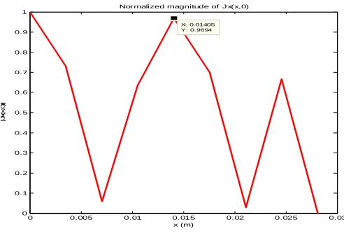
We remark, according to Fig. 4, that the current density checks the physical conditions of the real current. In fact, has a sinusoidal form, whose period is the guided wavelength , along the propagation direction
and its value at the end of the microstrip line is close to zero.
0 0.005 0.01 0.015 0.02 0.025 0.03
0 0.1 0.2 0.3 0.4 0.5 0.6 0.7 0.8 0.9 1
X: 0.01405 Y: 0.9694
Normalized magnitude of J x(x,0)
x (m)
|J
x(
x
,0
)|
Fig. 4. Magnitude of J(x,0) on the uniform microstrip line.
Fig. 5, which describes , shows that this component is maximum at the edges of the line.
-5 0 5
x 10-3
0.88 0.9 0.92 0.94 0.96 0.98 1
Normalized magnitude of Jx(0,y)
y (m)
|J
x(
0
,y)
|
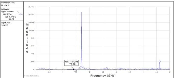
We have simulated the microstrip line with the commercial software, as shown in Fig. 7 to compare the calculated value of reflection coefficient S11 at the frequency 4 GHz. The magnitude of the calculated value according to Fig. 6 is 70, while the measured value is 70.28.
0 2000 4000 6000 8000 10000
0 10 20 30 40 50 60 70
Number of TE and TM modes
[Z
in
|
Convergence of input impedance
16 trial functions 64 trial functions 256 trial functions
Fig. 6. Convergence of input impedance on the uniform microstrip line.
Fig. 7. Results of SONNET software.
4.2. Analysis of infinite microstrip line
As second example, we study a laterally shielded top open microstrip line as described in Fig.2. We applied one-dimensional wavelet bases.
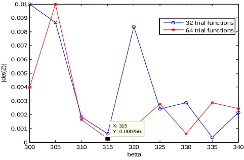
The convergence is obtained only for 64 trial functions and 2500 TE and TM modes. Results are compared to [15] and are in good agreement as shown in Fig. 9. For each frequency, we varied the value of until the determinant of the matrix Z is equal or close to zero. So it is a graphic resolution as described in Fig. 8.
5. Conclusion
A new formulation of the Moment Method was presented in this paper to solve electromagnetic problem. The conventional MoM algorithm was combined to the generalized equivalent circuit method to get an original formulation. This technique is based on the impedance operator and is applied to microstrip structures.
Furthermore, the obtained results are conformed to theory with respect to the boundary conditions and they are reasonably in good agreement with previously published data.
300 305 310 315 320 325 330 335 340
0 0.001 0.002 0.003 0.004 0.005 0.006 0.007 0.008 0.009 0.01 X: 315 Y: 0.000256 betta |d e t( Z )|
32 trial functions 64 trial functions
Fig. 8. Determination of ß for F=6 GHz.
2 3 4 5 6 7 8 9 10
100 150 200 250 300 350 400 450 500 550 Frequency (GHz) be tt a
results of [15] our results
Fig. 9. Dispersion curve of the fundamental mode of the infinite microstrip line.
References
[1] Mei, K.K. (1965): On the integral equations of thin-wire antennas, IEEE Trans, Antennas Propagat., AP-13, pp.374-378. [2] Harrington, R.F. (1968). Field Computation by Moment Metods. New York: Macmillan.
[3] Beylkin, G.; Coifman , R.; Rokhin, V. (1991): Fast wavelet transforms and numerical algorithms I, Commun. Pure Appl. Math., 44, pp. 141-183.
[4] Aubert, H. ; Baudrand, H. (2003). L’Electromagnétisme par les Schémas Equivalents, Cepaduès Editions.
[5] Sarkar, T. K.; Arvas, E.; Rao M. (1986): Application of FFT and the conjugate gradient method for the solution of electromagnetic radiation from electrically large and small conducting bodies, IEEE Trans. Antennas Propagat., 34, pp. 635-640.
[6] Steinberg, B. Z.; Leviatan ,Y. (1993): On the use of wavelet expansions in the method of moments,” IEEE Trans. Antennas and Propagat., 41(5), pp. 610-619.
[7] Zhu, X.; Dogaru, T.; Carin, L. (2003): Three-Dimensional BiorthogonalMultiresolution Domain Method and its Application to Electromagnetic Scattering Problems, IEEE Trans. Antennas and Propagat., 51(5), pp. 1085-1092.
[8] Baudrand , H. (1990): Representation by equivalent circuit of the integral methods in microwave passive elements, European Microwave Conference, 2, pp. 1359-1364, Budapest, Hungary.
[9] Markuwitz, N. (1986). Waveguide Handbook, Wiley-Interscience, New York.
[10] Collin, E. R. (2001): Foundations for Microwave Engineering, Donald G.Dudley, Series Editor, IEEE Press.
[11] LU, W.; CUI, T.; ZHAO, H. (2007): Acceleration of fast multipole method for large-scale periodic structures with finite sizes using sub-entiredomain basis functions, IEEE Transactions on Antennas and Propagation, 55, pp. 414–421.
[12] Daubechies , I. (1990): The wavelet transform time frequency localization and signal analysis, IEEE Trans. Tnfo. Theory, 36(5), pp. 961-1005.
[13] Golik, W. L. (1998): Wavelet packet for fast solution of electromagnetic integral equation, IEEE Trans. Antennas Propagation, 46(5). [14] Mallat, S.: A theory for multiresolution signal decomposition: the wavelet representation, IEEE Trans Pattern.
[15] Aubert, H. ; Baudrand, H. (2003). L’Electromagnétisme par les Schémas Equivalents, Cepaduès Editions.