Real Time Control of Three-Phase Shunt
Active Power Filter (SAPF) by
Instantaneous Reactive Power Theory using
dSPACE
Arvind A. Bondre1,E Vijay Kumar2, Nilesh M.Chamat3, Dr.Bhoopendra Singh4
1
.P.G. Student, Dept. of Electrical Engg. R.K.D.F. Institute of Science and Technology, Bhopal (M.P.), India
2
.H.O.D., Dept. of Electrical Engg. R.K.D.F. Institute of Science and Technology,Bhopal(M.P.),India
3
. P.G. Student, Dept. of Electrical Engg. Walchand College of Engineering, Sangli (M.S.), India
4
.Assistant Professor, Dept. of Electrical Engg. R.G.T.U., Bhopal(M.P.),India E-mail Id:, [email protected], [email protected]
Abstract—Use of nonlinear loads has been increased in large extent in industries now-a-days which injects
harmonic currents in supply system. These harmonics creates power quality issue. Shunt Active Power Filter (SAPF) is the popular and efficient solution to reduce these harmonics. SAPF can overcome voltage sag, eliminate harmonics and improves power factor. SAPF reduces total harmonic distortion (THD) to acceptable level. Reference current generation is the heart of APF. Reference current generation using instantaneous reactive power (IRP) theory is presented in this paper. IRP theory is widely used to control active power filters (APFs). Modeling of this technique is implemented in MATLAB/simulink. The system is experimentally implemented using DS1104 card of dSPACE system.
Key Words—SAPF, Power quality, IRP Theory, THD, MATLAB/simulink, dSPACE DS1104.
I. INTRODUCTION
Power quality issue is becoming very serious now-a-days. This is because non linear loads such as electrical machines, static power converters, electric arc furnaces, etc. which mainly lead to harmonic disturbances in power lines. Also power electronic equipments for human comfort plays major role in it. Although these power electronic equipments make our life convenient, it injects lot of harmonic current to the supply system and affects power factor [1]. Conventionally, passive LC filters have been used to eliminate line current harmonics and thereby increase the load power factor. Tuned passive filters are very effective for the elimination of specific harmonic components but has some drawbacks, such as
Fixed Compensation, Resonance,
huge size
They may cause series and load resonances in the system Also its performance depends on load, it gets affected significantly due to the variation in the filter component values, filter component tolerance, source impedance and frequency of ac source [1]. Shunt Active Power Filter (SAPF) is the effective solution to these problems. Active Filters can be designed to achieve following goals [2]:
Harmonic Compensation Harmonic Isolation
Reactive power compensation Voltage regulation
3-ph SAPF
3-ph source
Coupling inductor
Non-linear load
DC link capacitor
Figure 1. Basic structure of SAPF
In this paper reference current generation using IRP theory is presented. The experimental setup is done using DS1104 card of DSPACE system. Finally simulation and experimental results are presented.
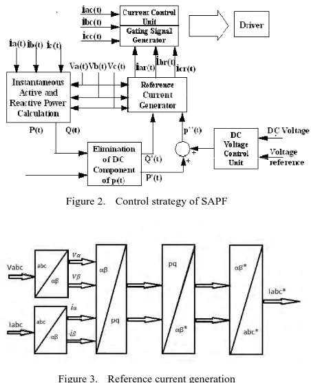
II. CONTROL STRATEGY
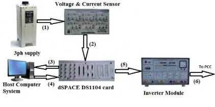
Key factor for successful implementation of SAPF is strategy Control s. Block diagram of control strategy is shown in figure 2 below. In this paper SAPF is controlled using instantaneous reactive power theory (IRP) or p-q theory. Using IRP theory, reference current will be generated. These reference currents will be further used to generate gate pulses for inverter. The basic principle of reference current generation is shown in figure 3 below.
Figure 2. Control strategy of SAPF
Figure 3. Reference current generation
IRP theory was first introduced by Akagi in 1983. It is now widely used to estimate compensating signals. It is also known as Clark Transformation for three phase current and voltages [2].
This method is based on transformation of three phase voltage and current signals into αβ0 stationary reference frame. In this method, first three phase voltages and currents are converted into αβ0 using following equations [2],
αβ 2/3
1 1/2 1/2
0 √3/2 √3/2
1/√2 1/√2 1/√2
αβ 2/3
1 1/2 1/2
0 √3/2 √3/2
1/√2 1/√2 1/√2
. (2)
Active and reactive power for three phase system can be given as following equations (3) and (4),
p =vα·iα + vβ·iβ (3)
q =vα ·iβ - iα·vβ (4)
Matrix form of the above equations can be given as eq. (5),
α α · α (5)
Active and reactive power can be separated in two parts i.e. AC and DC as following equation (6) and (7),
p = (6)
q = (7)
In order to get DC part of active and reactive power, p and q signals need to be passed through low pass filter. It will filter out high frequency components and will give expected signals i.e. fundamental part.
As per p-q theory, active power is given by DC part of α-β reference current, it can be given as following equation (8),
iαβ*= ² (8)
Further, actual three phase reference currents can be given as following equation (9),
iabc* = 2/3
1 0
1/2 √3/2
1/2 √3/2
iαβ* (9)
These currents are compared with source currents and obtained error is processed through PI to generate reference current for APF. IRP theory has advantage that obtained fundamental components of active and reactive power are DC quantities. As these signals are DC quantities, αβreference frame is unaffected by any phase shift introduced by low pass filter.
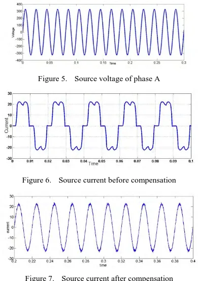
III. EXPERIMENTAL PROTOTYPE
The real time SAPF controller consist of dSPACE DS1104 interfacing card, current and voltage sensors, inverter consisting IGBTs as switches and a host computer system. The interfacing kit is fixed in host computer system. The experimental setup is as shown in figure below in figure 4,
Figure 4. Experimental setup
IV. SIMULATION RESULTS
The proposed system is simulated in MATLAB/simulink along with the control technique proposed in figure 2 and 3. The system is simulated in MATLAB/ simulink having phase to phase 400v, and frequency of 50 Hz. along with control technique, non linear load and gate pulse generation. SAPF is connected to supply system through very small coupling inductor. The simulation is performed on three phase balanced non linear load; as a result of this following results are obtained.
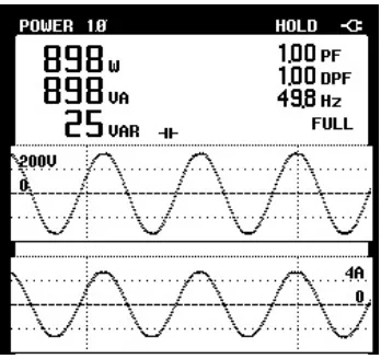
Following figures 5, 6 & 7 shows source voltage of phase A, source current before compensation and source current after compensation respectively.
Figure 5. Source voltage of phase A
Figure 6. Source current before compensation
Figure 7. Source current after compensation
The load current for phase A is obtained as fallows in figure 8. Also filter current for phase A is obtained as fallows in figure 10,
Figure 8. Load Current for phase A
Figure 9. Filter current for phase A
Figure 10. THD of system
V. EXPERIMENTAL RESULTS
The proposed system is experimentally performed using DS1104 card of dSPACE system. The following results are taken by using FLUKE 43B Power Quality Analyzer,
Figure 11. Active & Reactive power of phase A
The sum of all active powers in experimental setup measured by FLUKE meter is found to be 3114W. This value is verified by using dSPACE DS1104 card is as shown below, and it is found to be 3098W.
Figure 14. Total Active Power by dSPACE system.
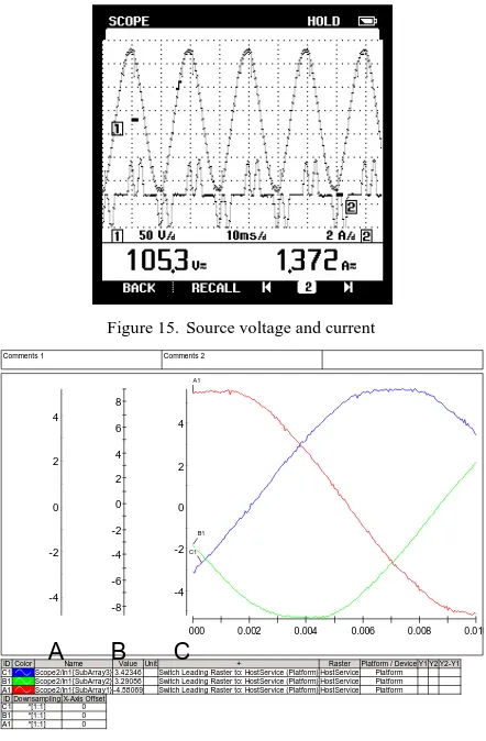
The source voltag and current obained are as fallows in figure 15. Also figure 16 shows the reference currents geerated using p-q theory.
Figure 15. Source voltage and current
Figure 16. Reference currents generated
VI. CONCLUSION
Reference current is the key factor for successful performance of SAPF. The reference current using instantaneous reactive power theory is presented in this paper. Further these reference currents are used to generate switching pulses for inverter. THD can be maintained to acceptable level using SAPF. The simulation results using MATLAB/simulink verifies that. The system is implemented by using dSPACE DS1104. The experimental results are stated in the paper. The advantages of IRP theory are that it is easy to implement, less mathematical calculations. IRP or p-q theory can effectively and efficiently be used to control shunt active power filters.
0 1000 2000 3000
A
.000 0.001 0.002 0.003 0.004 0.005 0.006 0.007 0.008 0.009
A1
Comments 1 Comments 2
-4 -2 0 2 4 A -8 -6 -4 -2 0 2 4 6 8 B -4 -2 0 2 4 C
000 0.002 0.004 0.006 0.008 0.010
A1
B1
C1
ID Color Name ValueUnit + Raster Platform / Device Y1 Y2 Y2-Y1 C1 Scope2/In1{SubArray3} 3.42346 Switch Leading Raster to: HostService (Platform) HostService Platform B1 Scope2/In1{SubArray2} 3.29086 Switch Leading Raster to: HostService (Platform) HostService Platform A1 Scope2/In1{SubArray1} -4.58069 Switch Leading Raster to: HostService (Platform) HostService Platform ID Downsampling X-Axis Offset
VII. REFERENCES
[1] M. Waware, P. Agarwal, “A Review of multilevel Inverter Based Active Power Filter” , International Journal of Computer and
Electrical Engineering, Vol. 3, No. 2, April, 2011 1793-8163 196
[2] Musa Yusup Lada, Ismadi Bugis, Md Hairul Nizam Talib, “Simulation a Shunt Active Power Filter using MATLAB/Simulink” , The
4th International Power Engineering and Optimization Conf. (PEOCO2010), Shah Alam, Selangor, MALAYSIA: 23-24 June 2010
[3] María Isabel Milanés Montero, Enrique Romero Cadaval, Fermín Barrero González, “Comparison of Control Strategies for Shunt
Active Power Filters in Three-Phase Four-Wire Systems” , IEEE transactions on power electronics, vol. 22, no. 1, january 2007
[4] Hirofumi Akagi, Hyosung Kim, “The Instantaneous Power Theory on the Rotating p-q-r Reference Frames” , IEEE 1999 International
Conference on Power Electronics and Drive Systems, PEDS'99, July 1999, Hong Kong
[5] Smita Singhai, Bharti Dewani, “Implementation of Active Harmonic Filter with MATLAB/Simulink to compensate Non-Linear
Loads” ,International Journal of Digital Application and Contemporary research, Volume 1, Issue 9, April 2013
[6] Maoh-Chin Jiang, “Analysis and Design of a Novel Three-Phase Active Power Filter” , IEEE transactions on aerospace and electronic
systems vol. 37, no. 3 july 2001
[7] Jaime Prieto, Patricio Salmerón, Reyes S. Herrera, “Practical Design of a Load Compensation Active Conditioner”, project by the
CICYT (Ministerio de Ciencia y Tecnología, Spain).
[8] N. Mendalek, K. AI-Haddad, F. Fnaiech and L.A. Dessaint, “Nonlinear control technique to enhance dynamic performance of a shunt
active power filter” ,IEE Proc-Electr. Power Appl,Vol. 150, No. 4, July 2003.
[9] M. Suresh, S.S.Patnaik, Y. Suresh, Prof. A.K. Panda, “Comparison of Two Compensation Control Strategies for Shunt Active Power
Filter in Three Phase Four-Wire System” , 978-1-61284-220-2/11/ ©2011 IEEE
Arvind Bondre has B.E. (Electrical) from Govt. College of Engg Chandrapur, India, in 2010. He is currently pursuing his M.Tech in Power Electronics, from R.K.D.F. institute of science and technology, Bhopal (M.P.), India under the guidance of Prof. Mr. E. Vijay Kumar.