CP7G
Discount
© 2000 Square D20
PRESSURE, VAC, TEMP AND FLOAT SWITCHES
Float Switches
Class 9036 – Types D and G
For additional information, reference catalog number 9034CT9701 or D-Fax™ number 1571, 1572, 1573.
Order universal mounting bracket and float accessory kits separately from Class 9049 section. Types GW and GR use center hole float. Devices with Form C use Centerhole float. All others use tapped at top float. See Page 18-8 for 9049 accessories.
cNet Buoyancy of float has been calculated with float 80% submerged, thus allowing 20% factor of safety.
aBuoyancy data above is calculated for use in water. Consult factory for buoyancy data media having specific gravity different than water. When ordering Float Accessories, first specify the desired Float Accessory Package such as 9049 A-6, 9049 A-6CS, etc., then as a second item give the number of additional rod Kits required. For Example: To get a 9049 A-6 with 15 feet of rod, order as follows: Item A (1) 9049A6
Item B (4) 9049T1
Refer to page 20-8 for Float Accessories.
qCompensating Spring not effective in combination with SHORT Lever length position.
For Open Tank Or Sump Applications
Class 9036 2 Pole Single Lever Operated
Description NEMA Type 1 NEMA Type 4 NEMA Type 7, 9
Type Price Type Price Type Price Contacts Close on Liquid Rise . . . DG2 $35.60 DW31 $236. DR31 $227. Contacts Open on Liquid Rise . . . DG2R 38.80 DW31R 239. DR31R 230. Contacts Close on Liquid Rise . . . GG2 68.00 GW1 397. GR1 388. Contacts Open on Liquid Rise . . . GG2R 68.00 GW1R 404. GR1R 397.
Modifications For Type DG, DW, DR
Factory Installed Field Installed Form Price 9049 Kit Price Reverse Action (Type DG) R $ 3.30 A58 $3.30 Compensating Spring (Type DG) C 6.50 A19 6.50 Compensating Spring (Type DR, DW) C 6.50 A20 6.50 Comp. Spring and Reverse Action CR 9.80 Not Available Modifications For Type GG, GW, GR
Factory Installed Field Installed Form Price 9049 Kit Price Compensating Spring for Type GG2 C 8.10 9049A13 8.10 Combination of Comp. Spring & Reverse
Action (Type GG2) CR 17.70 9049A13 8.10
1 N.O.-1 N.C. Contact Configuration H 9.60 Not Available Combination of Comp. Spring & 1 N.O.-1 N.C.
Contact for Type GG2 CH 17.70 Not Available
Reverse Action (Type GR, GW) R 9.60 Not Available
Maximum Forces At Which Switches Are Tested (in ounces)
Type Force Up
To Trip
Force Down To Trip
Will Support This Weight With Compensating Spring DG2 9 8 60 DG2 Form R 8 8 60 DW31 8 8 66 DW31 Form R 8 8 66 DR31 8 8 66 DR31 Form R 8 8 66
Class 9049 Float Accessory Specifications – In Ounces
Item Type A6 Type A6S Type A6C Type A6CS Type A6A Type A6CA Net Buoyancya (in Water) 7" Float . 60 c 60 c 70 c 70 c 60 c 70 c
Weight of 5 foot rod . . . 18.5 16.9 18.5 16.9 6 6 Weight of Extra Ft. of rod
(Per Ft.) . . . 3.7 3.4 3.7 3.4 1.2 1.2 Total Weight of Stops . . . 3 (2) 3 (2) 6 (4) 6 (4) 3 (2) 6 (4)
Type (with or without FORM H) Lever Length POSITION Force Up to Trip Force Down to Trip
Will Support This Weight With Compensating Spring at Max. Adj. in Ozs.
GG2 Short 33 39 q GG2 Long 21 27 100 GG2 Form R Short 30 24 q GG2 Form R Long 22 16 150 GR1, GW1 Short 24 31 80 GR1, GW1 Medium 22 29 72 GR1, GW1 Long 20 27 64 Type DG2 Type GG
CP7G
Discount
© 2000 Square D20
PRESSURE, VAC, TEMP AND FLOAT SWITCHES
Type FG and LG – Sumptrol
®Sump Pump Float Switch – Class 9036
The Class 9036 Type FG-30 pedestal style float switch is designed for liquid level control with electric
motor operated pumps either directly or through a magnetic starter. It can also be used to activate alarms
in liquid level control systems. The upward of downward movement of the lever arm of the Class 9036 Type
FG-30 float switch controls the ON and OFF positions corresponding to the water levels changes required
to turn the pump or alarm on and off.
The Class 9036 Type LG float switch automatically controls submersible sump, effluent and sewage
pumps either directly or through a magnetic starter. It can also be used to activate alarms in water or
sewage systems. The Type LG is a universal replacement for most small sump, effluent and sewage pump
float switches. This float switch does NOT contain mercury. The Type LG is omnidirectional and
functions properly regardless of orientation.
Description Type Price
Contacts close on liquid rise FG-30 2 pole NEMA Type 1 $15.00
Accessories
Description Number Required Class Type Price
Plastic center hole float 1 9049 A60 $ 4.00
33.75 inch aluminum rod, 2 float stop
assemblies and attaching hardware 1 9049 A61 4.00
Electrical Ratings
Voltage
Single Phase Unterminated Rating Plug Rating
Recommended Maximum Horsepower
120Vac, 50/60 Hz 15 Amps 12 Amps 1
/2 HP max.
230Vac, 50/60Hz 15 Amps 12 Amps 1 HP max.
Electrical Contacts: Snap action, normally open
Differential Angle: 85 degrees +/- 10 degrees
Housing Material: Polypropylene
Temperature Range:
Ambient Operating: +32˚F to +140˚F (0˚C to +60˚C)
Storage: -40˚F to +185˚F (-40˚C to +85˚C)
Dimensions: 3.01 in. (76.4 mm) diameter
5.10 in. (130 mm) length
Cord: #16 AWG, 2 conductor, SJOW-A, flexible cord,
water resistant to 140˚F (60˚C)
Maximum Tether Length: 36 inches
Description Price 9036LG1120B, 115 Vac Plug, 10 feet of cord $37.30 9036LG1120C, 230 Vac Plug, 10 feet of cord 37.30 Cord per foot 1.00 Without plug deduct 6.20
For additional information, reference catalog number 9034CT9701 or D-Fax™ number 1571, 1572, 1573.
Contacts Closed Type LG1
For pump down applications Contacts Open 0.32 8 4.85 123 3.01 76 (APPROX.) Type LG Type FG File LR78493 Class 321106 File E149970 CCN REUZ2
Type Numbering Codes: Class 9036 Type LG
X
XXX
X
XXX
1. Basic Type: LG
2. Contact Arrangement: one digit
3. Cord Length: three digits
4. Cord Termination: one letter
5. Packaging: up to three digits
1. Basic Type: LG
2. Contact Arrangement: . . . 1 — Normally Open (for pump down or high level alarm)
2 — Normally Closed (for pump up or low level alarm)
3 — Normally Open control circuit rated.
3. Cord Length: In inches (up to 20 feet), eg. 12 indicates 12 inches of cord
4. Cord Termination: A = Bare wires
B = 115 Vac Piggyback plug
C = 230 Vac Piggyback plug
5. Packaging: C20 for bulk of 20 pieces
CP7G
Discount
20
PRESSURE, VAC, TEMP AND FLOAT SWITCHES
© 2000 Square D
NOTE: The Cut-in point cannot be adjusted to less than 31/
2" from the top of the tank.
The Cut-out point cannot be less than 51/ 2" plus the
distance from the end of the ground link to the bottom of the tank.
Shown with 9049 ER-3 Rod Kit and 9049 EF-1 Float Kit installed.
Mounting Dimensions for Class 9037 Types D and E
Type EG
Type D switches are completely self-contained units composed of switch mechanism, mounting flange,
center hole float, and float rod.
tThe travels listed above also apply to the NEMA Type 7 and 9 (DR) and NEMA Type 4 (DW) Versions.
Type E switches are flange mounted and float movement is transmitted through a stuffing box.
Build up the switch to meet your exact requirements from the basic switch, float rod and float groups
below. Switch may be assembled in the field to give contacts that open on liquid rise or close on liquid rise.
Class 9037 Type D Contacts Close On Liquid Rise Ground Link Length
“A” Distance
NEMA Type 1 NEMA Type 4 NEMA Type 7 and 9 Type Price Type Price Type Price 17" DG1 $335. DW1 $537. DR-1 $528. 23" DG2 353. DW2 555. DR2 543. 29" DG3 368. DW3 570. DR3 561. 35" DG4 385. DW4 587. DR4 576. 41" DG5 401. DW5 602. DR5 593. 47" DG6 416. DW6 618. DR6 609. 53" DG7 434. DW7 635. DR7 624. 59" DG8 449. DW8 651. DR8 642.
Available Factory Modifications
Note: Standard materials are: Float: #304 S.S. Float Guide Rod: #316 S.S. Ground Post and Cross Tie: Brass Stop Collars: Brass
Omit Float and Rod Accessories . . . Form L1 . . . . deduct . . . . $ 51.50 Omit Rod Accessories . . . Form L2 . . . . deduct . . . . 10.30 Reverse action, Contacts open on liquid rise. . . Form R . . . add . . . 20.70 #316 stainless steel Float and rod
accessories . . . Form Z5
“A” distance . . . 17" . . . add . . . 182.00 23" . . . add . . . 193.00 29" . . . add . . . 204.00 35" . . . add . . . 213.00 41" . . . add . . . 224.00 47" . . . add . . . 233.00 53" . . . add . . . 245.00 59" . . . add . . . 255.00
Table Of Adjustment In Inches
tType “A”
Link Length
“B” Approx. Water Level Change Minimum Maximum DG1 17" 31/ 2" 8" DG2 23" 31/ 2" 14" DG3 29" 31/ 2" 20" DG4 35" 31/ 2" 26" DG5 41" 31/ 2" 32" DG6 47" 31/ 2" 38" DG7 53" 31/ 2" 44" DG8 59" 31/ 2" 50"
Float Switches
Class 9037 – Types D and E – Closed Tank
For additional information, reference catalog number 9034CT9701 or D-Fax™ number 1571, 1572, 1573.
Class 9049 Floats for Type E Switches #304 S.S. . . EF1 $19.50 #316 S.S. . . . EF2 48.40
Class 9049
Float Rod Kits “R” “H” Price Type ER1 13 /4" 81/4" $8.10 Type ER2 21 /2" 91/2" 8.10 Type ER3 31 /2" 91/2" 8.10 Type ER5 51 /4" 113/4" 8.10 Type ER7 71 /4" 133/4" 8.10 Type ER12 121 /4" 183/4" 8.10 Class 9037 Type E Post Length “L” NEMA Type 1 NEMA Type 4 NEMA Type 7 & 9
Application Type Price Type Price Type Price
EG8 $132. EW8 $334. ER8 $325. For Minimum Water Level Change
25
/8"
EG10 146. EW10 348. ER10 337. 411/
16"
EG9 132. EW9 334. ER9 325. For Maximum Water Level
Change 25
/8"
EG13 146. EW13 348. ER13 337. 411/
16"
For additional information refer to Product Data Bulletin A-84.
Consult factory for use in media having specific gravity different than water.
3.5 88.9 B 5.5 139.7 4356-C1 A 5.75 146 Dia. 5.125 130.18 B.C. 4.41 112.02 0.125 3.18 Bead (4) 0.41 Dia. 10.4 Holes L R H 4.5 114.3 A F 1.81 45.97 3.63 92.2
CP7G
Discount
© 2000 Square D20
PRESSURE, VAC, TEMP AND FLOAT SWITCHES
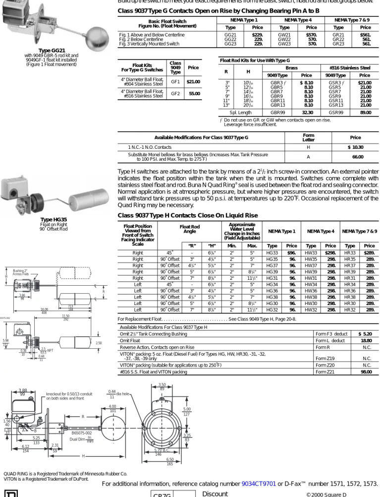
Types G, H – Closed Tank – Class 9037
Type G switches are flange mounted and float movement is transmitted through a bellows seal.
Build up the switch to meet your exact requirements from the basic switch, float rod and float groups below.
Type H switches are attached to the tank by means of a 2
1/
2
inch screw-in connection. An external pointer
indicates the float position within the tank when the unit is mounted. Switches come complete with
stainless steel float and rod. Buna N Quad Ring
®seal is used between the float rod and sealing connector.
Normal application is at atmospheric pressure, but where higher pressures are encountered, the switch
will withstand tank pressures up to 50 p.s.i. at temperatures up to 220˚F. Occasional replacement of the
Quad Ring may be necessary.
Class 9037 Type G Contacts Open on Rise by Changing Bearing Pin A to B
Basic Float Switch Figure No. (Float Movement)
NEMA Type 1 NEMA Type 4 NEMA Type 7 & 9 Type Price Type Price Type Price Fig. 1 Above and Below Centerline GG21 $229. GW21 $570. GR21 $561. Fig. 2 Below Centerline GG22 229. GW22 570. GR22 561. Fig. 3 Vertically Mounted Switch GG23 229. GW23 570. GR23 561.
Float Kits For Type G Switches
Class 9049 Type
Price 4" Diameter Ball Float,
#304 Stainless Steel GF1 $21.00 4" Diameter Ball Float,
#316 Stainless Steel GF2 55.00
Available Modifications For Class 9037 Type G Form
Letter Price
1 N.C.-1 N.O. Contacts H $ 10.30 Substitute Monel bellows for brass bellows (Increases Max. Tank Pressure
to 100 PSI. and Max. Temp. to 275˚F) A 66.00
Class 9037 Type H Contacts Close On Liquid Rise
Float Position Viewed from Front of Switch Facing Indicator Scale Float Rod Angle Approximate Water Level Change in Inches (Field Adjustable)
NEMA Type 1 NEMA Type 4 NEMA Type 7 & 9
“R” “H” Min. Max. Type Price Type Price Type Price
Right 45˚ - 63 /8" 2" 5" HG33 $96. HW33 $298. HR33 $289. Right 90˚ Offset 3" 43/ 8" 2" 5" HG35 96. HW35 298. HR35 289. Right 90˚ Offset 41/ 4" 53/8" 2" 7" HG37 96. HW37 298. HR37 289. Right 90˚ Offset 5" 63 /8" 2" 81/4" HG39 96. HW39 298. HR39 289. Right 90˚ Offset 7" 83 /8" 2" 111/2" HG31 96. HW31 298. HR31 289. Left 45˚ - 63/ 8" 2" 5" HG34 96. HW34 298. HR34 289. Left 90˚ Offset 3" 43/ 8" 2" 5" HG36 96. HW36 298. HR36 289. Left 90˚ Offset 41 /4" 55/8" 2" 7" HG38 96. HW38 298. HR38 289. Left 90˚ Offset 5" 63 /8" 2" 81/4" HG30 96. HW30 298. HR30 289. Left 90˚ Offset 7" 87/ 8" 2" 111/2" HG32 96. HW32 298. HR32 289.
For Replacement Float . . . See Class 9049 Type H, Page 20-8. Available Modifications For Class 9037 Type H
Omit 21/
2" Tank Connecting Bushing Form F3 deduct $ 5.20
Omit Float Form L deduct 18.80
Reverse Action, Contacts open on Rise Form R N.C.
VITON®
packing: 5 oz. Float (Diesel Fuel) For Types HG, HW, HR30, -31, -32,
-37, -38, -39 only Form Z19 N.C.
VITON® packing (suitable for applications up to 250˚F) Form Z20 N.C.
#316 S.S. Float and VITON packing Form Z21 98.00
Type GG21 with 9049 GBR-5 rod kit and
9049GF-1 float kit installed (Figure 1 Float movement)
Type HG35 Float on Right 90˚ Offset Rod H 3.86 98 Bushing 2" Across Flats 16.06 408 11.50 292 713 184 R CL CL 2.58 2.5 63.5NPT 0.44 11 0.38 10 5.98 152 C65075-062
fDo not use on GR or GW when contacts open on rise. Leverage force insufficient.
Float Rod Kits for Use With Type G
R H Brass #316 Stainless Steel
9049 Type Price 9049 Type Price 3" 105 /16 GBR3 f $ 8.10 GSR3 f $21.00 5" 125 /16 GBR5 8.10 GSR5 21.00 7" 145 /16 GBR7 8.10 GSR7 21.00 9" 165 /16 GBR9 8.10 GSR9 21.00 11" 185 /16 GBR11 8.10 GSR11 21.00 13" 205 /16 GBR13 8.10 GSR13 21.00 Spl. Length GBR99 32.30 GSR99 89.00
QUAD RING is a Registered Trademark of Minnesota Rubber Co. VITON is a Registered Trademark of DuPont.
3.88 99 1.56 40 1.31 33 A B 5.25 133 6.12 154 2.31 59 R H knockout for 0.50/13 conduit on both sides and front
B65075-002 In mm Dual Dim 0.44 11 4.00 101 dia hole 6.50 165 5.75 146 B.C. 3.25 83 5.00 127 3.50 89
CP7G
Discount
20
PRESSURE, VAC, TEMP AND FLOAT SWITCHES
© 2000 Square D
Float Switches
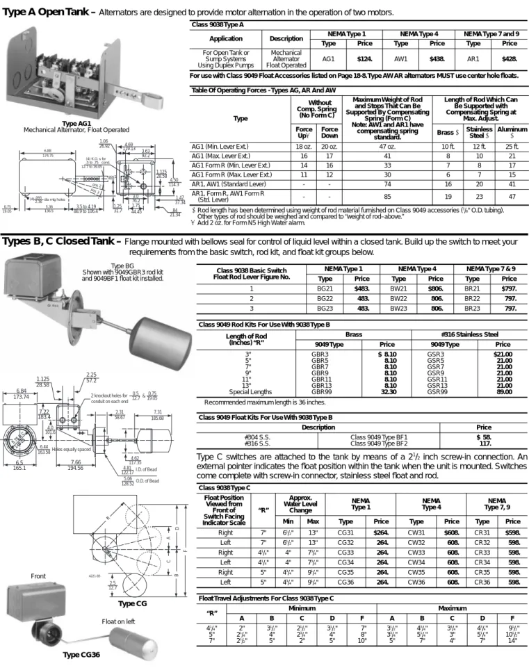
Class 9038 – Types A, B, C – Mechanical Alternators
For additional information, reference catalog number 9034CT9701 or D-Fax™ number 1571, 1572, 1573.
For Replacement Float, see Type 9049 HF . . . .Page 20-8Type AG1
Mechanical Alternator, Float Operated
Float on left Front
Type CG36
Type CG
Type A Open Tank –
Alternators are designed to provide motor alternation in the operation of two motors.
For use with Class 9049 Float Accessories listed on Page 18-8. Type AW AR alternators MUST use center hole floats.
cRod length has been determined using weight of rod material furnished on Class 9049 accessories (3
/8" O.D. tubing).
Other types of rod should be weighed and compared to “weight of rod–above.”
qAdd 2 oz. for Form N5 High Water alarm. Class 9038 Type A
Application Description NEMA Type 1 NEMA Type 4 NEMA Type 7 and 9 Type Price Type Price Type Price For Open Tank or
Sump Systems Using Duplex Pumps
Mechanical Alternator Float Operated
AG1 $124. AW1 $438. AR1 $428.
Table Of Operating Forces - Types AG, AR And AW
Type
Without Comp. Spring
(No Form C)
Maximum Weight of Rod and Stops That Can Be Supported By Compensating
Spring (Form C) Note: AW1 and AR1 have
compensating spring standard.
Length of Rod Which Can Be Supported with Compensating Spring at Max. Adjust. Force Upq Force Down Brass c Stainless Steel c Aluminum c
AG1 (Min. Lever Ext.) 18 oz. 20 oz. 47 oz. 10 ft. 12 ft. 25 ft.
AG1 (Max. Lever Ext.) 16 17 41 8 10 21
AG1 Form R (Min. Lever Ext.) 14 16 33 7 8 17
AG1 Form R (Max. Lever Ext.) 11 12 30 6 7 15
AR1, AW1 (Standard Lever) - - 74 16 20 41
AR1, Form R, AW1 Form R
(Std. Lever) - - 85 19 23 47
aRecommended maximum length is 36 inches.
Type C switches are attached to the tank by means of a 2
1/
2
inch screw-in connection. An
external pointer indicates the float position within the tank when the unit is mounted. Switches
come complete with screw-in connector, stainless steel float and rod.
Class 9038 Basic Switch Float Rod Lever Figure No.
NEMA Type 1 NEMA Type 4 NEMA Type 7 & 9 Type Price Type Price Type Price 1 BG21 $483. BW21 $806. BR21 $797. 2 BG22 483. BW22 806. BR22 797. 3 BG23 483. BW23 806. BR23 797. Class 9049 Rod Kits For Use With 9038 Type B
Length of Rod (Inches) “R”
Brass #316 Stainless Steel 9049 Type Price 9049 Type Price 3" GBR3 $ 8.10 GSR3 $21.00 5" GBR5 8.10 GSR5 21.00 7" GBR7 8.10 GSR7 21.00 9" GBR9 8.10 GSR9 21.00 11" GBR11 8.10 GSR11 21.00 13" GBR13 8.10 GSR13 21.00 aSpecial Lengths GBR99 32.30 GSR99 89.00
Class 9049 Float Kits For Use With 9038 Type B
Description Price #304 S.S. #316 S.S. Class 9049 Type BF1 Class 9049 Type BF2 $ 58. 117. Class 9038 Type C Float Position Viewed from Front of Switch Facing Indicator Scale “R” Approx. Water Level Change NEMA Type 1 NEMA Type 4 NEMA Type 7, 9 Min Max Type Price Type Price Type Price Right 7" 61 /2" 13" CG31 $264. CW31 $608. CR31 $598. Left 7" 61/ 2" 13" CG32 264. CW32 608. CR32 598. Right 41/ 4" 4" 73/4" CG33 264. CW33 608. CR33 598. Left 41/ 4" 4" 73/4" CG34 264. CW34 608. CR34 598. Right 5" 43 /4" 91/4" CG35 264. CW35 608. CR35 598. Left 5" 43/ 4" 91/4" CG36 264. CW36 608. CR36 598. Float Travel Adjustments For Class 9038 Type C
“R” Minimum Maximum A B C D F A B C D F 41/ 4" 2" 31/2" 21/2" 31/2" 7" 31/2" 43/4" 33/4" 43/4" 91/2" 5" 21/ 4" 4" 23/4" 4" 8" 33/4" 51/4" 3" 51/4" 101/2" 7" 21/ 2" 5" 2" 5" 10" 5" 7" 4" 7" 14" .84 21.34 1.47 37.34 1.125 28.58 4.50 114.3 3.0 76.2 1.75 44.45 1.25 31.7 3.5 to 4.19 88.9 to 106.4 pos1 pos 2 pos 3 5.38 136.5 (4) .093 2.36dia mtg holes 0.75 19.05 6.88 174.75 .5 to .75 12.7 to 19.05 cond. (4) K.O. s for 4.69 119.13 3.63 92.2 1.06 26.92 Type BG Shown with 9049GBR3 rod kit and 9049BF1 float kit installed.
Types B, C Closed Tank –
Flange mounted with bellows seal for control of liquid level within a closed tank. Build up the switch to meet your
requirements from the basic switch, rod kit, and float kit groups below.
R A D F C B 2.5 12.7 4221-83 6.84 173.74 6.5 165.1 7.66 194.56 7.22 183.4 4.0 101.6 2.25 57.2 1.125 28.58 5.75 B .C. 146.05 6.44
163.58Holes equally spaced
7.31 185.68 2.31 58.67 0.5 12.7 0,75 19.05 & 2 knockout holes for conduit on each end
4.62 117.35 4.81 122.17I.D. of Bead 5.06 128.52O.D. of Bead
CP7G
Discount
© 2000 Square D20
PRESSURE, VAC, TEMP AND FLOAT SWITCHES
Type D Mechanical Alternators are designed for applications where mounting is to be made
at the top of a closed tank.
Type J Mechanical Alternators are flange mounted vertical action. Switches are complete
including float. Float movement is transmitted through a stuffing box.
Consult factory for use in media having specific gravity different than water. Class 9038 Type D Contacts Close On Liquid Rise
Water Level Change
Hinge Post Dimension
“V”
NEMA Type 1 NEMA Type 4 NEMA Type 7 and 9 Type Price Type Price Type Price Min. 25 /8" DG7 $319. DW7 $661. DR7 $652. Max. DG8 319. DW8 661. DR8 652. Min. 411 /16" DG9 331. DW9 676. DR9 664. Max. DG10 331. DW10 676. DR10 664. Float Kits For Use With Type D Switches
Size and Material Class and Type Price Diameter x Length
35
/8" x 41/2", #304 S.S. Class 9049 Type EF1 $19.50
35/
8" x 41/2", #316 S.S. Class 9049 Type EF2 48.40
21
/2" x 7", #304 S.S. Class 9049 Type HF3 21.00
21/
2" x 7", #316 S.S. Class 9049 Type HF4 66.00
Class 9038 Type J Contacts Close On Liquid Rise Ground Link
Length “A” Distance
NEMA Type 1 NEMA Type 4 NEMA Type 7 and 9 Type Price Type Price Type Price 17" JG1 $497. JW1 $820. JR1 $810. 23" JG2 514. JW2 837. JR2 826. 29" JG3 530. JW3 853. JR3 844. 35" JG4 546. JW4 869. JR4 859. 41" JG5 562. JW5 885. JR5 876. 47" JG6 578. JW6 900. JR6 891. 53" JG7 595. JW7 918. JR7 907. 59" JG8 611. JW8 934. JR8 924. Adjustment In Inches Type “A” Link Length “B”
Water Level Change to Effect Normal Alternation of Two Pumps Minimum Maximum JG1 17" 4-7 /16" 7-1/16" JG2 23" 4-7/ 16" 13-1/16" JG3 29" 4-7 /16" 19-1/16" JG4 35" 4-7/ 16" 25-1/16" JG5 41" 4-7 /16" 31-1/16" JG6 47" 4-7/ 16" 37-1/16" JG7 53" 4-7 /16" 43-1/16" JG8 59" 4-7/ 16" 49-1/16"
Available Modifications For All Mechanical Alternators
Sub. monel bellows for standard brass bellowsseal (Type BG, BR, BW) . . . Form A. . . Add . . . $66.00 Compensating spring (Type AG) . . . Form C . . . Add . . . 25.80 Omit 21
/2" connecting bushing (Type CG, CR, CW) . . Form F3. . . deduct . . 5.20
Omit Float (Type CG, CR, CW) . . . Form L . . . deduct . . . 18.80 Omit Float and rod accessories (Type J) . . . Form L1 . . . deduct . . . 51.50 Omit Rod accessories (Type JG, JR, JW) . . . Form L2 . . . deduct . . . 10.30 Manual transfer selector . . . Form N3 . . . add . . . 36.00 (Enables operator to select which of two pumps will always “lead” or come on first, with the “lag” or second pump operating only under peak demand conditions or if first pump fails. When disengaged, unit reverts to normal alternation.)
Two level non-alternating unit . . . Form N4 . . . add . . . 36.00 Addition of a third, high water alarm Circuit (Type AG, AR, AW, CG, DG only) Form N5 . . . add . . . 86.00 Reverse action (contacts open on Rise). . . Form R . . . N.C. Sub. #316 S.S. Float and rod accessories . . . Form Z5
(Type JG, JR, JW) A = 17". . . add . . . . 182.00 A = 23". . . add . . . . 193.00 A = 29". . . add . . . . 204.00 A = 35". . . add . . . . 213.00 A = 41". . . add . . . . 224.00 A = 47". . . add . . . . 233.00 A = 53". . . add . . . . 245.00 A = 59" . . . add . . . . 255.00 VITON®
packing 5 oz. float (Diesel Fuel) (Type CG) Form Z19. . . . N.C. VITON packing (Type CG, CR, CW). . . Form Z20. . . . N.C. #316 S.S. Float and VITON Packing (Type CG, CR, CW) Form Z21. . . . 98.00
Float Rod Kit
Class 9049 “R” “H” Price Type ER1 13/ 4" 81/4" $8.10 Type ER2 21/ 2" 9" 8.10 Type ER3 31/ 4" 91/2" 8.10 Type ER5 51/ 4" 113/4" 8.10 Type ER7 71/ 4" 133/4" 8.10 Type ER12 121/ 4" 183/4" 8.10
Types D, J – Closed Tank – Class 9038
For additional information, reference catalog number 9034CT9701 or D-Fax™ number 1571, 1572, 1573.
31/32 V R H 4240-B2 B C A F D G Type DG with 9049 EF-1 Float
Type JG1
Type DG Shown with rod kit 9049ER5 and float kit
9049HF3 installed.
VITON is a Registered Trademark of DuPont.
6.84 173.7 2.42 61.4 5.56 141.2 of flange CL (4) K.O.s for.5 -.75 cond. on each end
4.47 113.5 2.53 64.3 1.187 30.15 2.44 61.98 1.5 38.1 5.75 146.05 5.125 130.18 4.41 112.01 .125 3.175bead 4.41 112.01dia. Mtg. Holes 4240-86 A B C D 5.5 139.7 3.25 82.55 .97 24.64 1.47 37.34 (2 pls)
CP1 CP7G
Discount
20
PRESSURE, VAC, TEMP AND FLOAT SWITCHES
© 2000 Square D a600 volt DC rating does not apply.
Contacts are single pole, double throw — one circuit normally open and one circuit normally closed. These circuits are not electrically separate and can not be used on opposite polarities.
Type G Industrial
Contact Arrangementa Contact Symbol
1 N.O. – 1 N.C.
Temperature Ratings
Actuator Minimum Maximum Ambient All -23˚C (-10˚F) +85˚C (+185˚F)
Media
Diaphragm -40˚C (-40˚F)
+120˚C (+250˚F) Piston -26˚C (-15˚F)
All with Forms Q4 and Q14 -26˚C (-15˚F)
Snap switch contains two (2) double break contact elements (1 N.O. – and 1 N.C.) that must be used on circuits of same polarity.
Snap switch contains two electrically separated sets of contact elements allowing use on circuits of opposite polarity. Each set contains two double break contact elements (1 N.O. and 1 N.C.) that must be used on circuits of same polarity.
Type G Machine Tool, Temperature & Vacuum
(except GVG)
Type Contact Arrangement Contact Symbol Single PoleDouble Throw 1 N.O. – 1 N.C.
Type ArrangementContact ContactSymbol
Double Pole
Double Throw 2 N.O. – 2 N.C.
Control Duty Circuit Ratings
Contacts AC – 50 or 60 Hz DC AC or DC Volts Inductive 35% Power Factor Resistive 75% Power Factor Volts Inductive and Resistive Continuous Carrying Amperes
Make Break Make and
Break Amperes
Make and Break Amperes
Amps. VA Amps. VA Single
Throw Double Throw SPDT 120 60 7200 6 720 6 120 0.55 0.22 10 240 30 7200 3 720 3 250 0.27 0.11 10 480 15 7200 1.5 720 1.5 600 0.10 . . . . 10 600 12 7200 1.2 720 1.2 . . . . DPDT 120 60 7200 6 720 6 125 0.22 0.22 10 240 30 7200 3 720 3 250 0.11 0.11 10 480 15 7200 1.5 720 1.5 600 . . . 10 600 12 7200 1.2 720 1.2 . . . .
Electrical Ratings
Class 9012, 9013, 9016, 9025, 9035, 9036, 9037, and 9038
Temperature Limitations For All 9013 F
tAnd G Switches
Media Ambient Min. -30˚C (-22˚F)
Max. +125˚C (+257˚F)
Min. -30˚C (-22˚F) Max. +70˚C (+158˚F)
tFSG and FYG 32°F min. (0°C)
Maximum Allowable Pressure For All 9013 Switches
Type Pressure FHG, FSG, FYG, FSW, FYW FRG, GHB, GHG, GSB, GSG GMG, GSR, GSW GHR, GHW 220 PSIG 300 PSIG 100 PSIG 250 PSIG SAME POLARITY SAME POLARITY 1 3 2 4 SAME POLARITY
cDC Rating does not apply to Form M4.
a1/4 HP with Form MI.
qSee 1993 NEC Article 430-84
Electrical Ratings For All 9013 Switches
Switch Type Voltage Phase ACSingle Polyphase AC q DC
Control Circuit Rating FHG2, 9, 12, 13, 115 1 1 /2 HP 2 HP 1/4 HPc A600 44, 49 230 2 HP 3 HP 1 /4 HPc FSG, FSW 460/575 – 1 HP – FHG22, 29, 32, 115 2 HP 3 HP 1 /2 HPa A600 53, 54, 59 230 3 HP 5 HP 1 /2 HPa FYG, FYW 460/575 – 1 HP – FRG One Pole All Form H 32 – – – A300 115 1 HP – 1 /4 HP 230 1 HP – 1 /4 HP FRG Two Pole 32 – – 1 /4 HP A300 115 1 HP 1 HP 1 /4 HP 230 1 HP 1 HP 1 /4 HP All 9013G Form H 115 1 HP – 1 /2 HP A600 230 2 HP – 1 /2 HP 460/575 2 HP – – All 9013G Except Form H 115 2 HP 3 HP 1 HP A600 230 3 HP 5 HP 1 HP 460/575 5 HP 5 HP –
CONTROL CIRCUIT RATING: A600
Electrical Ratings - 9016 GVG Types
Voltage Single Phase AC Polyphase AC DC 110 V 2 HP 3 HP 1 HP 220 V 3 HP 5 HP 1 HP 440-550V 5 HP 5 HP 32 V 1 /2 HP
q See 1993 NEC Article 430-84
Electrical Ratings:
Applies to Class and Type
Single Phase AC Polyphase AC q DC Control Circuit 115V 230V 460/ 575V115V 230V 460/ 575V 32V 115V 230V 9035DG30, DR30, DW30 (2 pole) 2 hp 3 hp – 3 hp 5 hp 1 hp 1/ 4 hp 1/2 hp 1/2 hp A600 9035DG31, DR31, DW31 (1 NO, 1 NC) 1 hp 1 hp – – – – – 1/ 4 hp 1/4 hp A300 9036DG, DR, DW (2 pole), FG 2 hp 3 hp – 3 hp 5 hp 1 hp 1 /4 hp 1/2 hp 1/2 hp A600 9036GG, GR, GW (2 pole) 2 hp 3 hp 5 hp 3 hp 5 hp 5 hp 1 /2 hp 1 hp 1 hp A600 9036G Form H (1 NO, 1 NC) 1 hp 2 hp 2 hp – – – – 1 /2 hp 1/2 hp A300 9037DG, DR, DW; EG, ER, EW; HG, HR, HW (2 pole) 2 hp 3 hp – 3 hp 5 hp 1 hp 1/ 4 hp 1/2 hp 1/2 hp A600 9037GG, GR, GW (2 pole) 2 hp 3 hp 5 hp 3 hp 5 hp 5 hp 1 /2 hp 1 hp 1 hp A600 9037G Form H (1 NO, 1 NC) 1 hp 2 hp 2 hp – – – – 1 /2 hp 1/2 hp A300
9038 All Devices (2 pole) 2 hp 3 hp – 3 hp 5 hp 1 hp 1
/4 hp 1/2 hp 1/2 hp A600
Temperature Limitations For All Float Switches:
Ambient Min. -30˚C (-22˚F)
Max. 121˚C (250˚F)
CP1 CP7G
Discount
20
PRESSURE, VAC, TEMP AND FLOAT SWITCHES
© 2000 Square D a600 volt DC rating does not apply.
Contacts are single pole, double throw — one circuit normally open and one circuit normally closed. These circuits are not electrically separate and can not be used on opposite polarities.
Type G Industrial
Contact Arrangementa Contact Symbol
1 N.O. – 1 N.C.
Temperature Ratings
Actuator Minimum Maximum Ambient All -23˚C (-10˚F) +85˚C (+185˚F)
Media
Diaphragm -40˚C (-40˚F)
+120˚C (+250˚F) Piston -26˚C (-15˚F)
All with Forms Q4 and Q14 -26˚C (-15˚F)
Snap switch contains two (2) double break contact elements (1 N.O. – and 1 N.C.) that must be used on circuits of same polarity.
Snap switch contains two electrically separated sets of contact elements allowing use on circuits of opposite polarity. Each set contains two double break contact elements (1 N.O. and 1 N.C.) that must be used on circuits of same polarity.
Type G Machine Tool, Temperature & Vacuum
(except GVG)
Type Contact Arrangement Contact Symbol Single PoleDouble Throw 1 N.O. – 1 N.C.
Type ArrangementContact ContactSymbol
Double Pole
Double Throw 2 N.O. – 2 N.C.
Control Duty Circuit Ratings
Contacts AC – 50 or 60 Hz DC AC or DC Volts Inductive 35% Power Factor Resistive 75% Power Factor Volts Inductive and Resistive Continuous Carrying Amperes
Make Break Make and
Break Amperes
Make and Break Amperes
Amps. VA Amps. VA Single
Throw Double Throw SPDT 120 60 7200 6 720 6 120 0.55 0.22 10 240 30 7200 3 720 3 250 0.27 0.11 10 480 15 7200 1.5 720 1.5 600 0.10 . . . . 10 600 12 7200 1.2 720 1.2 . . . . DPDT 120 60 7200 6 720 6 125 0.22 0.22 10 240 30 7200 3 720 3 250 0.11 0.11 10 480 15 7200 1.5 720 1.5 600 . . . 10 600 12 7200 1.2 720 1.2 . . . .
Class 9012, 9013, 9016, 9025, 9035, 9036, 9037, and 9038
Temperature Limitations For All 9013 F
tAnd G Switches
Media Ambient Min. -30˚C (-22˚F)
Max. +125˚C (+257˚F)
Min. -30˚C (-22˚F) Max. +70˚C (+158˚F)
tFSG and FYG 32°F min. (0°C)
Maximum Allowable Pressure For All 9013 Switches
Type Pressure FHG, FSG, FYG, FSW, FYW FRG, GHB, GHG, GSB, GSG GMG, GSR, GSW GHR, GHW 220 PSIG 300 PSIG 100 PSIG 250 PSIG SAME POLARITY SAME POLARITY 1 3 2 4 SAME POLARITY
cDC Rating does not apply to Form M4.
a1/4 HP with Form MI.
qSee 1993 NEC Article 430-84
Electrical Ratings For All 9013 Switches
Switch Type Voltage Phase ACSingle Polyphase AC q DC
Control Circuit Rating FHG2, 9, 12, 13, 115 1 1 /2 HP 2 HP 1/4 HPc A600 44, 49 230 2 HP 3 HP 1 /4 HPc FSG, FSW 460/575 – 1 HP – FHG22, 29, 32, 115 2 HP 3 HP 1 /2 HPa A600 53, 54, 59 230 3 HP 5 HP 1 /2 HPa FYG, FYW 460/575 – 1 HP – FRG One Pole All Form H 32 – – – A300 115 1 HP – 1 /4 HP 230 1 HP – 1 /4 HP FRG Two Pole 32 – – 1 /4 HP A300 115 1 HP 1 HP 1 /4 HP 230 1 HP 1 HP 1 /4 HP All 9013G Form H 115 1 HP – 1 /2 HP A600 230 2 HP – 1 /2 HP 460/575 2 HP – – All 9013G Except Form H 115 2 HP 3 HP 1 HP A600 230 3 HP 5 HP 1 HP 460/575 5 HP 5 HP –
CONTROL CIRCUIT RATING: A600
Electrical Ratings - 9016 GVG Types
Voltage Single Phase AC Polyphase AC DC 110 V 2 HP 3 HP 1 HP 220 V 3 HP 5 HP 1 HP 440-550V 5 HP 5 HP 32 V 1 /2 HP
q See 1993 NEC Article 430-84
Electrical Ratings:
Applies to Class and Type
Single Phase AC Polyphase AC q DC Control Circuit 115V 230V 460/ 575V115V 230V 460/ 575V 32V 115V 230V 9035DG30, DR30, DW30 (2 pole) 2 hp 3 hp – 3 hp 5 hp 1 hp 1/ 4 hp 1/2 hp 1/2 hp A600 9035DG31, DR31, DW31 (1 NO, 1 NC) 1 hp 1 hp – – – – – 1/ 4 hp 1/4 hp A300 9036DG, DR, DW (2 pole), FG 2 hp 3 hp – 3 hp 5 hp 1 hp 1 /4 hp 1/2 hp 1/2 hp A600 9036GG, GR, GW (2 pole) 2 hp 3 hp 5 hp 3 hp 5 hp 5 hp 1 /2 hp 1 hp 1 hp A600 9036G Form H (1 NO, 1 NC) 1 hp 2 hp 2 hp – – – – 1 /2 hp 1/2 hp A300 9037DG, DR, DW; EG, ER, EW; HG, HR, HW (2 pole) 2 hp 3 hp – 3 hp 5 hp 1 hp 1/ 4 hp 1/2 hp 1/2 hp A600 9037GG, GR, GW (2 pole) 2 hp 3 hp 5 hp 3 hp 5 hp 5 hp 1 /2 hp 1 hp 1 hp A600 9037G Form H (1 NO, 1 NC) 1 hp 2 hp 2 hp – – – – 1 /2 hp 1/2 hp A300
9038 All Devices (2 pole) 2 hp 3 hp – 3 hp 5 hp 1 hp 1
/4 hp 1/2 hp 1/2 hp A600