Programming Research Group, Faculty of Science, University of Amsterdam
ABSTRACT
In previous work we described how the process algebra based language PSF can be used in software engineering, using the ToolBus, a coordination architecture also based on process algebra, as implementation model. We also described this software development process more formally by presenting the tools we use in this process in a CASE setting, leading to the PSF-ToolBus software engineering environment. In this article we summarize that work and describe a similar software development process for implementation of software systems using a client/server model and present this in a CASE setting as well.
Ke ywords: process algebra, software engineering, software architecture, client server architecture, webservices
1. Introduction
In previous work [9-11] we investigated the use of process algebra, in particular the process algebra based language PSF (Process Specification Formalism), in the software development process. We used the ToolBus, a process algebra based coordination architecture, as implementation model. We giv e a description of PSF and the ToolBus in sections 1.1 and 1.2. We described this software development process more formally in [12] by presenting the tools we use in the development process in a Computer-Aided Software Engineering Environment (CASE) setting.
In the work mentioned above we only used the ToolBus as target system model for implementing software systems. Our goal is to support software development with process algebra for other system models as well. In this article we describe how client / server based architectures can be developed using process algebra. Furthermore, we describe this process in a CASE setting leading to a software engineering environment.
In client / server architecture based software systems tasks are partioned between service providers (servers) and service requesters (clients). Such software systems consist of one or more clients that make use of services provided by one or more servers. But a server itself can also act as a client making requests to one or more other servers. In this way, a hierarchy is formed in which clients and servers on a lower level can make requests to servers on higher levels.
In the remainder of this section we give brief descriptions of PSF and the ToolBus. In section 2 we describe our software engineering process with PSF and the software engineering environment supporting this process. In section 3 we show how the modelling of client / server architectures in PSF can be achieved and in section 5 we describe this process more formally by presenting it in a CASE setting, leading to the PSF-Client / Server Software Engineering Environment. We briefly discuss the implementation of applications based on the specifications of client / server architectures in section 5. We end with sections on related work and conclusions.
1.1 PSF
PSF is based on ACP (Algebra of Communicating Processes) [3] and ASF (Algebraic Specification Formalism) [4]. A description of PSF can be found in [13, 14, 20, 21]. Processes in PSF are built up from the standard process algebraic constructs: atomic actions, alternative composition+, sequential composition ., and parallel composition || . Atomic actions and processes are parameterized with data parameters. PSF is accompanied by a Toolkit containing among other components a compiler and a simulator that can
be coupled to an animation [15]. The tools operate around the tool intermediate language (TIL) [22]. Animations can either be made by hand or be automatically generated from a PSF specification [16]. The animations play an important role in our software development process as they can be used to test the specifications and are very convenient in communication to other stakeholders.
1.2 ToolBus
The ToolBus [5] is a coordination architecture for software applications developed at CWI (Amsterdam) and the University of Amsterdam. It utilizes a scripting language based on process algebra to describe the communication between software tools. A ToolBus script describes a number of processes that can communicate with each other and with various tools existing outside the ToolBus. The role of the ToolBus when executing the script is to coordinate the various tools in order to perform some complex task. A language-dependent adapter that translates between the internal ToolBus data format and the data format used by the individual tools makes it possible to write every tool in the language best suited for the task(s) it has to perform.
ToolBus
PT1 Adapter Tool 1 PT2 Tool 2 AdapterFigure 1. Model of tool and ToolBus interconnection
In Figure 1 two possible ways of connecting tools to the ToolBus are displayed. One way is to use a separate adapter and the other to have a built-in adapter. Processes inside the ToolBus can communicate with each other using the actionssnd-msgandrec-msg. ToolBus processes can communicate with the tools using the actionssnd-doandsnd-eval. With the latter a tool is expected to send a value back which can be received by the process with the actionrec-value. A tool can send an event to a ToolBus process which can be received with the actionrec-event. Such an event has to be acknowledged by the ToolBus process with the actionsnd-ack-event.
2. Software Engineering with PSF
In [12], previous work on software engineering with PSF is summarized and put in a CASE setting, resulting in a software engineering environment based on process algebra. In this section we briefly describe this environment and give an example of its use.
2.1 The PSF-ToolBus Software Engineering Environment
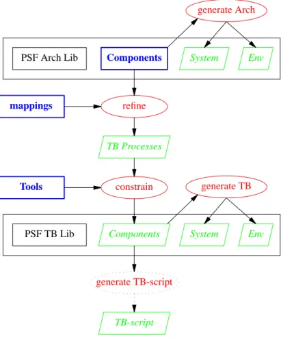
In Figure 2 we show the PSF-ToolBus software engineeringing environment that can be used for the development of ToolBus applications. Objects to be specified are presented as bold boxes, workbench tools asellipses, and generated objects asslanted boxes. The environment consist of two workbenches, one for the specification of the architecture of the software system, and one for the specification of the software system as ToolBus application. Each workbench uses a library of PSF modules in which the primitives for this particular abstraction level are specified. On each level the connection of the components into a system and the incorporation in an environment is generated from the components.
PSF Arch Lib Components System Env
Architecture specification
generate Arch
PSF TB Lib Components System Env
ToolBus application specification generate TB refine mappings TB Processes constrain Tools generate TB-script TB-script
Figure 2. The PSF-ToolBus Software Engineering Environment
systems from which a ToolBus application specification can be obtained by applying vertical and horizontal implementation techniques based on our process algebra. Vertical implementation is the refining of actions in the architecture specification by mapping these actions onto sequences of actions. Horizontal implementation is the constraining of the processes that are the result of the vertical implementation with processes that specificy the tools. A process can be constrained by another process by putting the processes in parallel with each other and enforcing communication between the two by encapsulation.
From the specification of the ToolBus processes in the ToolBus application specification a ToolBus script can be derived that together with the implementation for the tools form a ToolBus application. The derivation of the ToolBus script is not done automatically. The problem here is that PSF specifications use recursion for setting the state of a process, and the ToolBus cannot handle recursive processes.
2.2 Example
We show our development process for a small application. In this example, Component1 can either send a messageto Tool2 and then wait for an acknowledgement from Component2, or it can send aquitafter which the application will shutdown.
Architecture Specification
We first specify a module for the data and id’s we use. data module Data
begin exports begin
functions message : → DATA ack : → DATA quit : → DATA c1 : → ID c2 : → ID end imports ArchitectureTypes end Data
We then specify the system of our application. process module ApplicationSystem begin exports begin processes ApplicationSystem end imports Data, ArchitecturePrimitives atoms send-message stop processes Component1 Component2 definitions Component1 = send-message . snd(c1 >> c2, message) . rec(c2 >> c1, ack) . Component1 + stop . snd-quit Component2 = rec(c1 >> c2, message) . snd(c2 >> c1, ack) . Component2
ApplicationSystem = Component1 || Component2 end ApplicationSystem
Thesnd-quitin the process definition for Component1 communicates with the architecture environment followed by a disrupt to end all processes.
Next, we put the system in the architecture environment by means of binding the main process to the System parameter of the environment.
process module Application begin imports Architecture { System bound by [ System→ ApplicationSystem ] to ApplicationSystem renamed by [ Architecture → Application ] } end Application
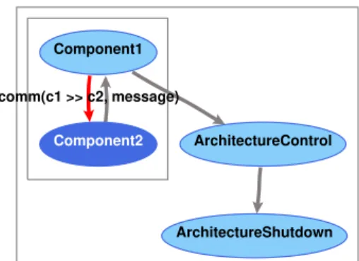
The generated animation of the architecture is shown in Figure 3. Here, Component1 has just sent a message to Component2, which is ready to send an acknowledgement back. Each box represents an encapsulation of the processes inside the box, and a darker ellipse is a process which is enabled to perform an action in the given state.
The module mechanism of PSF can be used to build more complex components hiding internal actions and sub-processes. With the use of parameterization it is even possible to make sev eral instances of a component.
Component1
Component2
ArchitectureShutdown ArchitectureControl comm(c1 >> c2, message)
Figure 3. Animation of an example architecture ToolBus Application Specification
We make a ToolBus application specification for our example in the form shown in Figure 1. By refining the specification of the architecture we obtain a ToolBus application specification for our example. Take the processComponent1from the architecture specification of our toy example.
Component1 = send-message . snd(c1 >> c2, message) . rec(c2 >> c1, ack) . Component1 + stop . snd-quit
We can make a virtual implementation by applying the mapping consisting of the refinements snd(c1 >> c2, message)→ tb-snd-msg(t1, t2, tbterm(message))
rec(c2 >> c1, ack) → tb-rec-msg(t2, t1, tbterm(ack)) . tb-snd-ack-event(T1, tbterm(message))
snd-quit → snd-tb-shutdown
and the renamings of the local actions
send-message → tb-rec-event(T1, tbterm(message))
stop → tb-rec-event(T1, tbterm(quit))
Renaming the processComponent1intoPT1gives the following result. PT1 = tb-rec-event(T1, tbterm(message)) . tb-snd-msg(t1, t2, tbterm(message)) . tb-rec-msg(t2, t1, tbterm(ack)) . tb-snd-ack-event(T1, tbterm(message)) . PT1 + tb-rec-event(T1, tbterm(quit)) . snd-tb-shutdown
We can show that Component1 and PT1 are vertical bisimular. Applying the renamings on process Component1and hiding of the actions to be refined results in
Component1’ =
tb-rec-event(T1, tbterm(message)) . τ . τ . Component1’ + tb-rec-event(T1, tbterm(quit)) .τ
Hiding of the actions in the refinements in processPT1results in PT1’ =
tb-rec-event(T1, tbterm(message)) . τ . τ .τ . PT1’ + tb-rec-event(T1, tbterm(quit)) .τ
It follows thatComponent1’andPT1’are rooted weak bisimilar.
We now make a horizontal implementation by constrainingPT1withTool1Adapter. PTool1 = Tool1Adapter || PT1
Tool1Adapter is itself an constraining of AdapterTool1 with Tool1 for which we give the definitions below. AdapterTool1 = tooladapter-rec(message) . tooltb-snd-event(tbterm(message)) . tooltb-rec-ack-event(tbterm(message)). tooladapter-snd(ack) . AdapterTool1 + tooladapter-rec(quit) . tooltb-snd-event(tbterm(quit)) Tool1 = snd(message) . rec(ack). Tool1 + snd(quit)
In this constraint, the communication between the actions tooladapter-rec and tooladapter-sndofAdapterTool1and the actionssndandrecofTool1are enforced.
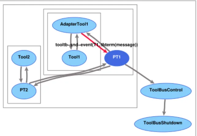
An implementation forComponent2can be obtained in a similar way. A generated animation is shown in Figure 4, in which AdapterTool1 just sent a message it had received from Tool1, to ToolBus process PT1.
PT1 ToolBusControl Tool1 ToolBusShutdown PT2 Tool2 AdapterTool1 tooltb−snd−event(T1, tbterm(message))
Figure 4. Animation of the ToolBus specification example Implementation
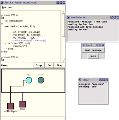
The implementation consists of three Tcl/Tk [29] programs (Tool1, its adapter, and Tool2), and a ToolBus script. A screendump of this application at work together with the viewer of the ToolBus is shown in Figure 5. With the viewer it is possible to step through the execution of the ToolBus script and view the variables of the individual processes inside the ToolBus. The ToolBus script is shown below. The executeactions in the ToolBus script correspond to starting the adapter for Tool1 and starting Tool2 in parallel with the processesPT1andPT2respectively.
process PT1 is let T1: tool1adapter in execute(tool1adapter, T1?) . ( rec-event(T1, message) . snd-msg(t1, t2, message) . rec-msg(t2, t1, ack) . snd-ack-event(T1, message) + rec-event(T1, quit) . shutdown("") ) * delta endlet process PT2 is let T2: tool2
Figure 5. Screendump of the example as ToolBus application with viewer in execute(tool2, T2?) . ( rec-msg(t1, t2, message) . snd-eval(T2, eval(message)). rec-value(T2, value(ack)) . snd-msg(t2, t1, ack) ) * delta endlet
tool tool1adapter is { command = "wish-adapter -script tool1adapter.tcl" } tool tool2 is { command = "wish-adapter -script tool2.tcl" }
toolbus(PT1, PT2)
The processes in the ToolBus script use iteration (*, where P * delta repeats P infinitely) and the processes in the PSF specification use recursion. In PSF it is also possible to use iteration in this case, since the processes have no arguments to hold the current state. On the other hand, in PSF it is not possible to define variables for storing a global state, so when it is necessary to hold the current state, this must be done through the arguments of a process and be formalized via recursion.
Following the description of the ToolBus processes is the description of how to execute the tools by the execute actions. The last line of the ToolBus script starts the processesPT1andPT2in parallel.
3. Modelling Client / Server Architectures
In this section we investigate the development of implementations based on a client/server architecture from an architecture specification in process algebra. The goal is to develop a software engineering environment for the development of software systems based on a client/server architecture, similar to the PSF-ToolBus software engineering environment described in section 2.
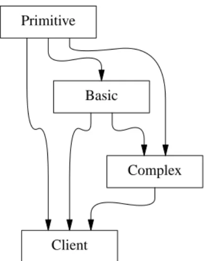
We do this using an application consisting of an operator which can request primitive operations to be performed on some data. We extend this application with basic operations that are build upon primitive operations, and with complex operations build upon basic and primitive operations. The hierarchy of clients and servers is shown in Figure 6.
Client
Complex Basic
Primitive
Figure 6. Hierachy of clients and servers 3.1 Architecture Specification
We start with the specification of the operator in its most simple form. In this form it can input some data, perform a primitive operation, and stop. After stopping, a snd-quit is send to the architecture environment in which this specification is put.
process module Operator begin exports begin processes Operator end imports ArchitecturePrimitives atoms input-data primitive-operation stop definitions Operator = ( input-data + primitive-operation + stop . snd-quit ) * delta end Operator
We refine theprimitive-operationby adding a sequence of skip (the PSF equivalent ofτ) actions to it with the use of the algebraic law a.τ =a. These skip actions are replaced withsndandrecactions for communication with another process which provides the services for the primitive operations. Our new architecture is given below with the specification of three modules. The first specifying the necessary data used by the other two.
data module ApplicationData begin exports begin functions operator : → ID primitive : → ID primitive-operation : → DATA result : → DATA end imports
ArchitectureTypes end ApplicationData
For convenience we only give the process definitions representing the operator and the process providing the services.
Operator = (
input-data
+ primitive-operation .
snd(operator, primitive, primitive-operation) . rec(primitive, operator, result)
+ stop . snd-quit ) * delta Primitive =
(
rec(operator, primitive, primitive-operation) . snd(primitive, operator, result)
) * delta
We extend our architecture specification with basic operations. We add the necessary data to the module ApplicationData and the following alternative sequence of actions to the iteration loop in module Operator.
+ basic-operation.
snd(operator, basic, basic-operation). rec(basic, operator, result)
We complete the extension with the addition of module Basic containing the following process definition. Basic =
(
rec(operator, basic, basic-operation). snd(basic, operator, result)
) * delta
A basic operation is build up from primitive operations. Therefor we extend therecaction with the use of the algebraic law a.τ =a and refine this into the computation of basic operations using services provided by thePrimitiveprocess.
Basic = (
rec(operator, basic, basic-operation). (
(
compute-basic .
snd(basic, primitive, primitive-operation) . rec(primitive, basic, result)
) *
result-basic .
snd(basic, c, result) )
) * delta
The inner loop looks similar to the process Operator with only primitive operations. To serve theBasic process, we extend thePrimitiveprocess.
Primitive = (
rec(operator, primitive, primitive-operation) . snd(primitive, operator, result)
+ rec(basic, primitive, primitive-operation) . snd(primitive, basic, result)
) * delta
We can generalize this using a sum construction. Primitive =
sum(c in ID,
rec(c, primitive, primitive-operation) . snd(primitive, c, result)
In a similar way we can add complex operations that are build up from basic and primitive operations. Complex =
(
rec(operator, complex, complex-operation) . (
(
compute-complex-primitive .
snd(complex, primitive, primitive-operation) . rec(primitive, complex, result)
+ compute-complex-basic .
snd(complex, basic, basic-operation) . rec(basic, complex, result)
) *
result-complex .
snd(complex, operator, result) )
) * delta
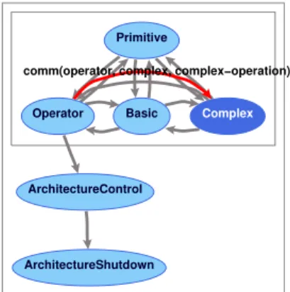
And we generalize process Basic with a sum construction as we did for the process Primitive. An animation of the complete architecture of the application is shown in Figure 7.
Complex Basic Operator ArchitectureShutdown ArchitectureControl Primitive
comm(operator, complex, complex−operation)
Figure 7. Animation of the application architecture 3.2 Client/Server Architecture Specification
Going back to our application consisting only of the processesOperatorandPrimitivewe see that one act as a client and the other as a server. We can hide the fact that the primitive operations are performed by a server through separating the communication with the server from the operator. We specify a client interface. C-I(client, server) = ( sum(s in SERVICE, c-rec-call(client, server, s) . cs-snd-request(client, server, s) ) . sum(r in RESULT, cs-rec-result(server, client, r) . c-snd-return(server, client, r) ) ) * delta
The operator can now be specified as a client as follows. C-Operator = C-I(operator, primitive) || Operator Operator = ( input-data + primitive-operation . c-snd-call(primitive, primitive-operation) .
c-rec-return(result) + stop .
snd-quit ) * delta
The operator as client is the constraining of the client interface C-I with the process Operator. Communication between these processes takes place through the set of client primitives consisting of the actionsc-snd-call,c-rec-call,c-snd-return, andc-rec-return.
We can also hide the communication of the server with the client from the execution of the services. S-I(server) = sum(c in ID, sum(s in SERVICE, cs-rec-request(c, server, s) . s-snd-call(server, s) ) . sum(r in RESULT, s-rec-return(server, r) . cs-snd-result(server, c, r) ) ) * delta
The primitive server can then be specified as the constraining of the server interface with the process Primitivedefined as follows.
S-Primitive = S-I(primitive) || Primitive Primitive = ( s-rec-call(primitive-operation) . s-snd-return(result) ) * delta
Communication between these processes takes place through the set of server primitive consisting of the actionss-snd-call,s-rec-call,s-snd-return, ands-rec-return.
Our application is formed by combining the processes C-Operator and S-Primitive which communicate through the set of client/server primitives consisting of the actionscs-snd-request, cs-rec-request,cs-snd-result, andcs-rec-result.
We hav e build a PSF library supporting client/server architecture specifications. This library is similar in setup as the PSF Architecture Library and the PSF ToolBus library. It contains parameterized modules for the client and server interface processes used above. The complete specification of this library can be found in Appendix A.
The processes Operator and Primitive are the result of applying the following mappings on the processes in the architecture specification.
snd(operator, $1, $2) → c-snd-call($1, $2) rec($1, operator, result) →
c-rec-return(result) rec($1, primitive, primitive-operation) →
s-rec-call(primitive-operation) snd(primitive, $1, result) →
s-snd-return(result)
Below we giv e the specification of our application with the use of the PSF Client/Server Architecture Library. The processes Operator and Primitive are defined in separate modules, which are not shown here.
process module C-Operator begin exports begin processes C-Operator end
imports ApplicationData, NewC-I { Name bound by [ client→ operator, server→ primitive ] to ApplicationData }, Operator definitions C-Operator = C-I(operator, primitive) || Operator end C-Operator
process module S-Primitive begin exports begin processes S-Primitive end imports ApplicationData, S-I { Name bound by [ server→ primitive ] to ApplicationData }, Primitive definitions S-Primitive = S-I(primitive) || Primitive end S-Primitive
We combine the two to form the application system. process module ApplicationSystem begin exports begin processes ApplicationSystem end imports NewServer { Server bound by [ Server→ S-Primitive ] to S-Primitive renamed by [ CS-Server → CS-Primitive ] }, NewClient { Client bound by [ Client→ C-Operator ] to C-Operator renamed by [ CS-Client → CS-Operator ] } definitions ApplicationSystem = CS-Primitive || CS-Operator end ApplicationSystem
And finally we put the application system in a client/server environment. process module Application
begin imports
ClientServer { System bound by [ System→ ApplicationSystem ] to ApplicationSystem renamed by [ ClientServer → Application ] } end Application
We extend the application with a server for the basic operations. First, we add a client interface for communication with the primitive operation server.
process module C-Basic begin exports begin processes C-Basic end imports ApplicationData, ServerPrimitives, NewC-I { Name bound by [ client→ basic, server→ primitive ] to ApplicationData }, Basic processes Services definitions C-Basic = C-I(basic, primitive) || Basic end C-Basic
To the resulting client we add a server interface. process module S-Basic
begin exports begin processes S-Basic end imports S-I { Name bound by [ server→ basic ] to ApplicationData }, NewClient { Client bound by [ Client→ C-Basic ] to C-Basic renamed by [ CS-Client → SC-Basic ] } definitions S-Basic = S-I(basic) || SC-Basic end S-Basic
It is also possible to add the server interface first and then add a client interface to the result. The basic operation server can now be added toApplicationSystem through the import of the library module NewServerand binding of its parameter to the processS-Basic.
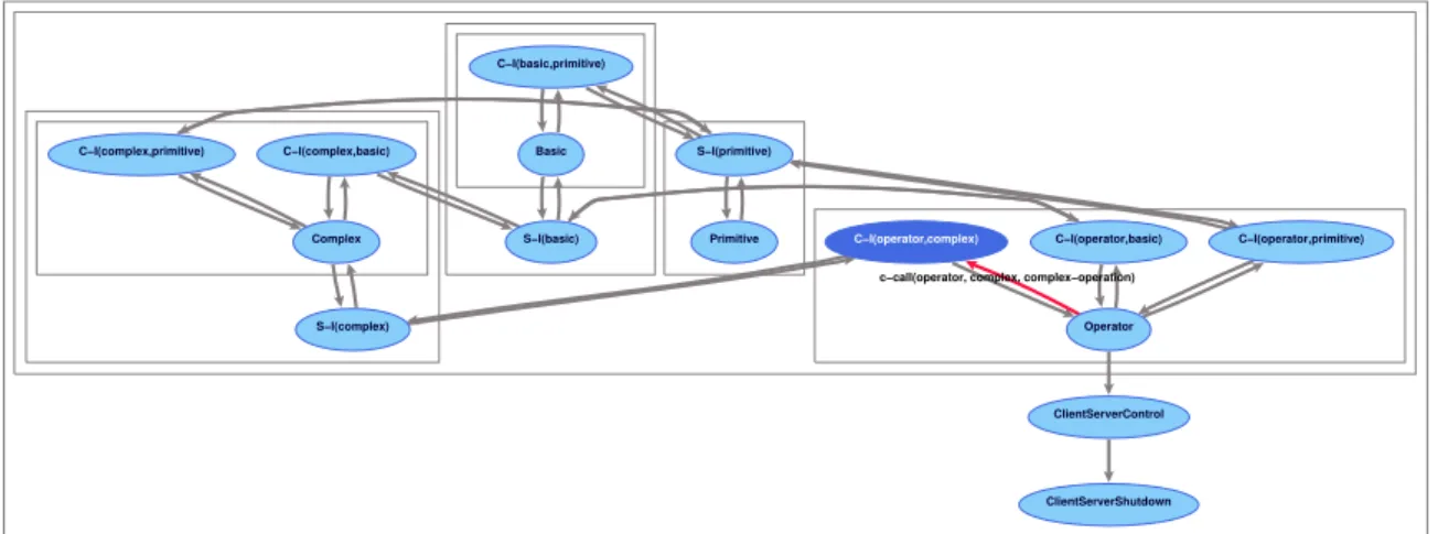
However, the server for the complex operations has two client interfaces, one for communication with the basic operations server and one for communication with the primiteve operations server.
An animation of the architecture of the client/server application is shown in Figure 8.
ClientServerControl Primitive S−I(basic) C−I(operator,basic) Operator Complex C−I(complex,primitive) C−I(operator,primitive) C−I(basic,primitive) S−I(complex) Basic ClientServerShutdown C−I(operator,complex) S−I(primitive) C−I(complex,basic)
c−call(operator, complex, complex−operation)
Figure 8. Animation of the client/server application architecture
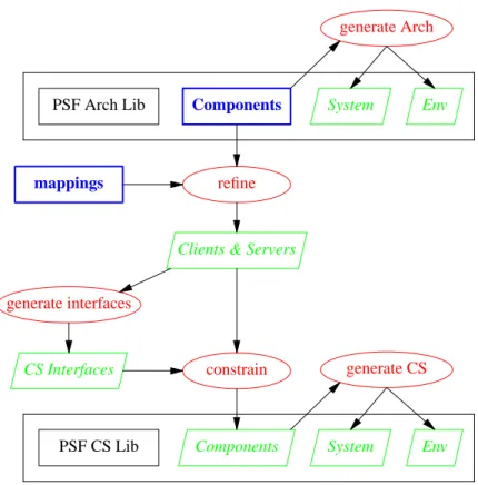
4. The PSF-Client / Server Software Engineering Environment
In the previous chapter we developed an architecture specification. From this architecture we developed a specification of client/server application by applying mappings on the processes of the architecture and constraining the resulting processes with client and server interface processes. We can describe the development process as a Software Engineering Environment (SEE) consisting of two workbenches, similar to the PSF-ToolBus SEE described in section 2. This PSF-Client/Server Software Engineering Environment is shown in Figure 9. Objects to be specified are presented asbold boxes, workbench tools as
ellipses, and generated objects asslanted boxes.
The PSF-Client/Server SEE differs from the PSF-ToolBus SEE in that here the tools are constrained with the processes that take care of the communication between the tools instead of the other way round. The reason for this is that there is no choice in how the communications between the clients and the servers take place, making it possible to apply what is called a pattern for the communications. Such a pattern is a generalized structure with parameters that are to be given a value when the pattern is applied.
Another difference is that the processes for constraining are generated from the processes that are constrained. This is possible since we can make use of a pattern for the communications between the clients and the servers. The values for the parameters of the patterns applied are deduced from the type of operations requested by the clients and servers and the knowledge of which operations a particular server can perform.
5. Client/Server Architecture based Implementations
From the client/server architecture specification a client/server based implementation can be developed. Such an implementation can be build using almost any implementation language. For a lot of implementation languages an extension package/library already exists that implements the client/server communication, hiding the encoding/decoding of the data used in the communication and hiding the details of the protocol used for the communication.
Through the hiding of the implementation details a request of a client with the receiving of the result of this request looks just like a function call. A server consist of a set functions representing the different services. The calling of these functions is done through a request handler that is hidden from the implementation of the services.
PSF Arch Lib Components System Env
Architecture specification
generate Arch
PSF CS Lib Components System Env
Client / Server application specification generate CS refine mappings
Clients & Servers
constrain generate interfaces
CS Interfaces
Figure 9. The PSF-Client/Server Software Engineering Environment
language combined with a package that implements web services based on Remote Procedure Calls (RPCs) and the Extensible Markup Language (XML) using the HTTP protocol. For a detailed description of programming web services with Perl we refer to [30].
6. Related Work
In the literature several architecture description languages have been proposed and some are based on a process algebra, such as Wright [2], Darwin [19], and PADL [6]. A comparison of several ADL’s can be found in [23]. Most of the ADL’s do not have any or very little support for refinement. SADL [24][25] however, has been specially designed for supporting architecture refinement. In SADL, different levels of specifications are related by refinement mappings, but the only available tool is a checker. LOT OS [7], a specification language similar to PSF, is used in [18] for the formal description of architectural styles as LOTOS patterns, and in [31] it is used as an ADL for the specification of middleware behaviour.
Formal development techniques such as B [1], VDM [17], and Z [8] provide refinement mechanisms, but they do not have support for architecture descriptions. Theπ-Method [26] has been built from scratch to support architecture-centric formal software engineering. It is based on the higher-order typedπ-calculus and mainly built around the architecture description languageπ-ADL [27] and the architecture refinement language π-ARL [28]. Tool support comes in the form of a visual modeler, animator, refiner, and code synthesiser.
Modelling client / server architectures can be done in the above mentioned ADL’s and development techniques. Some ADL’s provide patterns/styles for clients and server. In contrast to this, we showed that in our approach different types of components and the interaction with these components can be added in a relative easy manner.
To our knowledge there is no work done on generalizing software engineering workbenches and creating software engineering environment from instances of the generalized workbenches. There are many meta
software development environments with which an environment can be created by integrating a set of existing tools. Such integration can easily be developed with the PSF-ToolBus software engineering environment as is shown in [11]. Here, an integrated development environment for PSF is created from the tools of the PSF Toolkit using the ToolBus to control the communication between the tools.
7. Conclusions
We described how software systems based on a client / server architecture can be developed with process algebra in a similar way as described in previous work for software systems based on the ToolBus. We presented this development process more formally by presenting the tools used in this process in a CASE setting, resulting in the PSF-Client/Server SEE.
The PSF-Client/Server SEE differs from the PSF-ToolBus SEE in that the the processes for constraining can be generated from the processes that describe the clients and servers. This is due to the fact that we use a pattern for the communications between the clients and the servers, and the knowledge of which operations a particular server can perform.
References
[1] J.R. Abrial, The B-Book: Assigning Programs to Meanings, Cambridge University Press, 1996. [2] R. Allen and D. Garlan, ‘‘A Formal Basis for Architectural Connection,’’ ACM Transaction on
Software Engineering and Methodology, no. 6, pp. 213-249, 1997.
[3] J.A. Bergstra and J.W. Klop, ‘‘Process algebra: specification and verification in bisimulation semantics,’’ in Math. & Comp. Sci. II, ed. M. Hazewinkel, J.K. Lenstra, L.G.L.T. Meertens, CWI Monograph 4, pp. 61-94, North-Holland, Amsterdam, 1986.
[4] J.A. Bergstra, J. Heering, and P. Klint (eds.), ‘‘The Algebraic Specification Formalism ASF,’’ in Algebraic Specification, ACM Press Frontier Series, pp. 1-66, Addison-Wesley, 1989.
[5] J.A. Bergstra and P. Klint, ‘‘The discrete time ToolBus,’’ Science of Computer Programming, vol. 31, no. 2-3, pp. 205-229, July 1998.
[6] M. Bernardo, P. Ciancarini, and L. Donatiello, ‘‘Architecting Families of Software Systems with Process Algebras,’’ ACM Transactions on Software Engineering and Methodology, vol. 11, no. 4, pp. 386-426, 2002.
[7] T. Bolognesi and E. Brinksma, ‘‘Introduction to the ISO specification language LOTOS,’’ Computer Networks and ISDN Systems, vol. 14, pp. 25-59, 1987.
[8] J. Davies and J. Woodcock, Using Z: Specification Refinement and Proof, International Series in Computer Science, Prentice Hall, 1996.
[9] B. Diertens, ‘‘Software (Re-)Engineering with PSF,’’ report PRG0505, Programming Research Group - University of Amsterdam, October 2005.
[10] B. Diertens, ‘‘Software (Re-)Engineering with PSF II: from architecture to implementation,’’ report PRG0609, Programming Research Group - University of Amsterdam, November 2006.
[11] B. Diertens, ‘‘Software (Re-)Engineering with PSF III: an IDE for PSF,’’ report PRG0708, Programming Research Group - University of Amsterdam, October 2007.
[12] B. Diertens, ‘‘A Process Algebra Software Engineering Environment,’’ report PRG0808, Programming Research Group - University of Amsterdam, June 2008.
[13] B. Diertens, ‘‘New Features in PSF I - Interrupts, Disrupts, and Priorities,’’ report P9417, Programming Research Group - University of Amsterdam, June 1994.
[14] B. Diertens and A. Ponse, ‘‘New Features in PSF II - Iteration and Nesting,’’ report P9425, Programming Research Group - University of Amsterdam, October 1994.
[15] B. Diertens, ‘‘Simulation and Animation of Process Algebra Specifications,’’ report P9713, Programming Research Group - University of Amsterdam, September 1997.
[16] B. Diertens, ‘‘Generation of Animations for Simulation of Process Algebra Specifications,’’ report P2003, Programming Research Group - University of Amsterdam, September 2000.
[17] J. Fitzgerald and P. Larsen, Modeling Systems: Practical Tools and Techniques for Software Development, Cambridge University Press, 1998.
[18] M. Heisel and M. Levy, ‘‘Using LOTOS Patterns to Characterize Architectural Styles,’’ in Proc. of the 7th International Conference on Algebraic Methodology and Software Technology, LNCS, 1999. [19] J. Magee, N. Dulay, S. Eisenbach, and J. Kramer, ‘‘Specifying Distributed Software Architectures,’’ in
Proc. of the 5th European Software Engineering Conf. (ESEC ’95), pp. 137-153, LNCS, 1995. [20] S. Mauw and G.J. Veltink, ‘‘A Process Specification Formalism,’’ in Fundamenta Informaticae XIII
(1990), pp. 85-139, IOS Press, 1990.
[21] S. Mauw and G.J. Veltink (eds.), Algebraic Specification of Communication Protocols, Cambridge Tracts in Theoretical Computer Science 36, Cambridge University Press, 1993.
[22] S. Mauw and G.J. Veltink, ‘‘A Tool Interface Language for PSF,’’ report P8912, Programming Research Group - University of Amsterdam, October 1989.
[23] N. Medvidovic and R. Taylor, ‘‘A Classification and Comparison Framework for Architecture Description Languages,’’ IEEE Transactions on Software Engineering, vol. 26, no. 1, pp. 70-93, 2000. [24] M. Moriconi, X. Qian, and R.A. Riemenschneider, ‘‘Correct Architecture Refinement,’’ IEEE
Tr ansactions on Software Engineering, vol. 21, no. 4, 1995.
[25] M. Moriconi and R.A. Riemenschneider, ‘‘Introduction to SADL 1.0: A Language for Specifying Software Architecture Hierarchies,’’ technical report SRICSL9701, Computer Science Laboratory -SRI international, March 1997.
[26] F. Oquendo, ‘‘π-Method: A Model-Driven Formal Method for Architecture-Centric Software Engineering,’’ ACM Software Engineering Notes, vol. 31, no. 3, 2006.
[27] F. Oquendo, ‘‘π-ADL: An Architecture Description Language based on the Higher Order Typed
π-Calculus for Specifying Dynamic and Mobile Software Architectures,’’ ACM Software Engineering Notes, vol. 20, no. 3, 2004.
[28] F. Oquendo, ‘‘π-ARL: An Architecture Refinement Language for Formally Modelling the Stepwise Refinement of Software Architectures,’’ ACM Software Engineering Notes, vol. 29, no. 5, 2004. [29] J.K. Ousterhout, Tcl and the Tk Toolkit, Addison-Wesley, 1994.
[30] R.J. Ray and P. Kulchenko, Programming Web Services with Perl, O’Reilly & Associates, Inc., 2003. [31] N.S. Rosa and P.R.F. Cunha, ‘‘A Software Architecture-Based Approach for Formalising Middleware
Behaviour,’’ Electronic Notes in Theoretical Computer Science, vol. 108, pp. 39-51, 2004.
A. Client/Server Architecture Library data module ClientServerTypes begin exports begin sorts ID, SERVICE, RESULT end end ClientServerTypes
process module ClientServerPrimitives begin exports begin atoms cs-snd-request : ID # ID # SERVICE cs-rec-request : ID # ID # SERVICE cs-request : ID # ID # SERVICE cs-snd-result : ID # ID # RESULT cs-rec-result : ID # ID # RESULT cs-result : ID # ID # RESULT end imports ClientServerTypes communications
cs-snd-request(o, d, s) | cs-rec-request(o, d, s) = cs-request(o, d, s) for o in ID, d in ID, s in SERVICE
cs-snd-result(o, d, r) | cs-rec-result(o, d, r) = cs-result(o, d, r) for o in ID, d in ID, r in RESULT
end ClientServerPrimitives process module ServerPrimitives begin exports begin atoms s-snd-call : ID # SERVICE s-rec-call : SERVICE s-call : ID # SERVICE s-snd-return : RESULT s-rec-return : ID # RESULT s-return : ID # RESULT end imports ClientServerTypes communications
s-snd-call(n, s) | s-rec-call(s) = s-call(n, s) for n in ID, s in SERVICE
s-snd-return(r) | s-rec-return(n, r) = s-return(n, r) for n in ID, r in RESULT
end ServerPrimitives process module S-I begin parameters Name begin functions server : → ID end Name exports begin processes S-I : ID end imports ClientServerPrimitives, ServerPrimitives variables d : → ID
definitions S-I(server) = sum(o in ID, sum(s in SERVICE, cs-rec-request(o, server, s) . s-snd-call(server, s) ) . sum(r in RESULT, s-rec-return(server, r) . cs-snd-result(server, o, r) ) ) * delta end S-I
process module NewServer begin parameters Server begin processes Server end Server exports begin processes CS-Server end imports ServerPrimitives sets of atoms ServerH = { s-snd-call(n, s), s-rec-call(s), s-snd-return(r), s-rec-return(n, r) | n in ID, s in SERVICE, r in RESULT } definitions CS-Server = encaps(ServerH, Server ) end NewServer
process module ClientPrimitives begin exports begin atoms c-snd-call : ID # SERVICE c-rec-call : ID # ID # SERVICE c-call : ID # ID # SERVICE c-snd-return : ID # ID # RESULT c-rec-return : RESULT c-return : ID # ID # RESULT snd-quit end imports ClientServerTypes communications
c-snd-call(d, s) | c-rec-call(o, d, s) = c-call(o, d, s) for o in ID, d in ID, s in SERVICE
c-snd-return(o, d, r) | c-rec-return(r) = c-return(o, d, r) for o in ID, d in ID, r in RESULT
end ClientPrimitives process module NewC-I begin parameters Name begin functions client : → ID server : → ID
end Name exports begin processes C-I : ID # ID end imports ClientServerPrimitives, ClientPrimitives variables o : → ID d : → ID definitions C-I(client, server) = ( sum(s in SERVICE, c-rec-call(client, server, s) . cs-snd-request(client, server, s) ) . sum(r in RESULT, cs-rec-result(server, client, r) . c-snd-return(server, client, r) ) ) * delta end NewC-I
process module NewClient begin parameters Client begin processes Client end Client exports begin processes CS-Client end imports ClientPrimitives sets of atoms ClientH = { c-snd-call(d, s), c-rec-call(o, d, s), c-snd-return(o, d, r), c-rec-return(r) | o in ID, d in ID, s in SERVICE, r in RESULT } definitions CS-Client = encaps(ClientH, Client ) end NewClient
process module ClientServer begin parameters System begin processes System end System exports begin processes ClientServer end imports ClientServerPrimitives atoms rec-quit quit
snd-shutdown rec-shutdown shutdown processes ClientServerControl ClientServerShutdown sets of atoms H = { cs-snd-request(o, d, s), cs-rec-request(o, d, s), cs-snd-result(o, d, r), cs-rec-result(o, d, r) | o in ID, d in ID, s in SERVICE, r in RESULT } ClientServerH = { snd-quit, rec-quit, snd-shutdown, rec-shutdown } communications
snd-quit | rec-quit = quit
snd-shutdown | rec-shutdown = shutdown definitions ClientServer = encaps(ClientServerH, disrupt( encaps(H, System), ClientServerShutdown ) || ClientServerControl ) ClientServerControl = rec-quit . snd-shutdown ClientServerShutdown = rec-shutdown end ClientServer
B. An example implementation in Perl
We show how the application specified in section 3 can be implemented using web services. As an example we implement a calculator that can perform the operations on natural numbers. The operations consists ofsuccessor,predecessor, andiszeroas primitive operations,addandsubtractas basic operators, andmultiplyanddivideas complex operations. As implementation language we use Perl together with the Frontier-RPC package for implementing web services based on Remote Procedure Calls (RPC) and the Extensible Markup Language (XML) using the HTTP protocol. The package completely hides the XML and HTTP protocol details from the user.
The primitive operation server can be implemented as follows. use Frontier::Daemon; use Frontier::RPC2; my $d = Frontier::Daemon->new( methods => { succ => \&succ, pred => \&pred, iszero => \&iszero, }, LocalAddr => ’localhost’, LocalPort => 1080, ReuseAddr => 1, ); sub succ { my $arg = shift; return ++ $arg; } sub pred { my $arg = shift; if (iszero($arg)) { return 0; } else { return -- $arg; } } sub iszero { my $arg = shift; return $arg == 0 ? 1 : 0; }
The operator client can be implemented as follows use Frontier::Client; my $primitive = Frontier::Client->new( url => "http://localhost:1080/RPC2", debug => 0, ); my @stack = (); my @args; my $r; sub print_stack { my $s; $s = join(" ", @stack); print "($s)0; } while (1) { print_stack(); print "> "; # read input $_ = <>; if ($_ eq "") { next; } # strip input if (/\ˆ\s*(.*\S)\s*$/) { $_ = $1; } if (/\ˆ(\d+)$/) { # input natural push @stack, $1;
if ($#stack < 0) {
print "not enough arguments0; } else {
$args[0] = pop @stack;
$r = $primitive->call(’succ’, @args); print "$args[0] ++ = $r0;
push @stack, $r; }
} elsif ($_ eq "--") { # primitive predecessor if ($#stack < 0) {
print "not enough arguments0; } else {
$args[0] = pop @stack;
$r = $primitive->call(’pred’, @args); print "$args[0] -- = $r0;
push @stack, $r; }
} elsif ($_ eq "=") { # primitive iszero if ($#stack < 0) {
print "not enough arguments0; } else {
$args[0] = pop @stack;
$r = $primitive->call(’iszero’, @args); print "$args[0] == 0 = $r0;
push @stack, $r; }
} elsif ($_ eq "p") { # pop stack pop @stack;
} elsif ($_ eq "c") { # clear stack @stack = ();
} elsif ($_ eq "q") { # stop last;
} }
The basic operations client/server can be implemented as follows. use Frontier::Daemon; use Frontier::Client; my $primitive = Frontier::Client->new( url => "http://localhost:1080/RPC2", debug => 0, ); my $d = Frontier::Daemon->new( methods => { add => \&add, subtract => \&subtract, }, LocalAddr => ’localhost’, LocalPort => 1081, ReuseAddr => 1, ); sub add { my ($arg1, $arg2) = @_;
while (! $primitive->call(’iszero’, $arg2)) { $arg1 = $primitive->call(’succ’, $arg1); $arg2 = $primitive->call(’pred’, $arg2); }
return $arg1; }
sub subtract {
my ($arg1, $arg2) = @_;
while (! $primitive->call(’iszero’, $arg2) && ! $primitive->call(’iszero’, $arg1)) { $arg1 = $primitive->call(’pred’, $arg1); $arg2 = $primitive->call(’pred’, $arg2); }
return $arg1; }
The complex operations client/server can be implemented as follows. use Frontier::Daemon;
use Frontier::Client; my $primitive = Frontier::Client->new( url => "http://localhost:1080/RPC2", debug => 0, ); my $basic = Frontier::Client->new( url => "http://localhost:1081/RPC2", debug => 0, ); my $d = Frontier::Daemon->new( methods => { mul => \&multiply, div => \÷, }, LocalAddr => ’localhost’, LocalPort => 1082, ); sub multiply { my ($arg1, $arg2) = @_; my $r; $r = 0;
while (! $primitive->call(’iszero’, $arg2)) { $r = $basic->call(’add’, ($r, $arg1)); $arg2 = $primitive->call(’pred’, $arg2); } return $r; } sub lessthan { my $arg1 = shift; my $arg2 = shift; my $r;
$r = $basic->call(’subtract’, $arg2, $arg1); $r = $primitive->call(’iszero’, $r); return $r == 0 ? 1 : 0; } sub divide { my ($arg1, $arg2) = @_; my $r = 0; if (! $primitive->call(’iszero’, $arg2)) { while (! lessthan($arg1, $arg2)) {
$arg1 = $basic->call(’subtract’, ($arg1, $arg2)); $r = $primitive->call(’succ’, $r);
} }
return $r; }