http://researchcommons.waikato.ac.nz/
Research Commons at the University of Waikato
Copyright Statement:
The digital copy of this thesis is protected by the Copyright Act 1994 (New Zealand). The thesis may be consulted by you, provided you comply with the provisions of the Act and the following conditions of use:
Any use you make of these documents or images must be for research or private study purposes only, and you may not make them available to any other person. Authors control the copyright of their thesis. You will recognise the author’s right
to be identified as the author of the thesis, and due acknowledgement will be made to the author where appropriate.
You will obtain the author’s permission before publishing any material from the thesis.
The Development of a Brain
Controlled Robotic Prosthetic
Hand
A thesis
submitted in fulfilment
of the requirements for the degree
of
Master of Engineering
at
The University of Waikato
by
Mahonri Owen
i
Abstract
An anthropomorphic, brain controlled, under actuated, Prosthetic hand has been
designed and developed for upper extremity amputees. The hands function is based
on micro servo actuation and the use of coupling links between parts of the finger.
The control of a prosthetic hand is what differentiates this project from the others.
It is the intent of this project to increase the sense of belonging between prosthesis
and amputee by controlling the designed device by the brain of the amputee. The
platform has been designed to use multiple force sensors to improve control. The
project is a feasibility study and will be used to test whether a multi-functional and
intuitive prosthetic hand is attainable. The control of the hand will be driven through
a neural interface and controlled by a micro-board. This paper focuses on the
mechanical design of the hand and the processes used to control the hand using
signals emitted from the brain, to increase the sense of belonging between the
amputee and prosthetic device. The hand has been developed as a foundation for
iii
Acknowledgements
As I reflect over the past year I would like to recognise those individuals who have been responsible for my academic progress and who have got me to where I am today. I would like to express my heartfelt gratitude to my wife Ruby Owen and my son Alma Shane Taviri whom I could not have completed my studies without. I would also like to mention my mother for her support and my supervisor Dr Chi Kit Au for his ongoing academic support.
I would like to recognise the financial support granted from the health research council of New Zealand. I am also grateful for the support of my iwi and Te Tumu Paeroa for their contributions towards my studies.
v
Table of Contents
Abstract ... i Acknowledgements ... iii Table of Contents ... v List of Figures ... ix 1 Chapter One ... 1 1.1 Introduction ... 1 1.2 Motivation ... 2 1.3 Objectives ... 3 1.4 Scope ... 4 2 Chapter Two ... 5 2.1 Prosthetics ... 5 2.1.1 History of Prosthetics ... 6 2.1.2 Types of Prosthetics ... 7 2.1.2.1Joint Prosthetics ... 8 2.1.2.2Arm Prosthetics ... 8 2.1.2.3Leg Prosthetics ... 9 2.1.2.4Cosmetic Prosthesis ... 102.1.3 Complexity versus Function ... 11
2.1.4 Degrees of Freedom ... 12
2.1.5 Abandonment and Success ... 16
2.1.6 Conclusion ... 17
2.2 Robotics ... 18
2.2.1 History of Robotics ... 19
2.2.2 Structure and Classification of Robots ... 20
2.2.3 Power source ... 20
vi
2.2.5 Method of Control ... 21
2.2.6 Geometry ... 22
2.2.7 Quantification of Prosthetic Hand Performance ... 22
2.2.8 Analysing Methods ... 23
2.2.8.1Kinematics ... 23
2.2.8.2Velocity Kinematics ... 24
2.2.8.3Jacobian Manipulator ... 24
2.2.8.4Trajectory Planning/Shape Matching ... 26
2.2.8.5Dimensionality Reduction ... 26 2.2.9 Latest Technology ... 28 2.2.9.1Neural Interface ... 28 2.2.9.2Electroencephalography ... 29 2.2.9.3Sensory Feedback ... 31 2.2.10 Conclusion ... 33 3 Chapter Three ... 35 3.1 Mechanical Design ... 35 3.2 Skeletal simplifications ... 36 3.2.1 Fingers ... 37 3.2.2 Thumb ... 39 3.2.3 Palm ... 40 3.3 Under actuation ... 42 3.4 Grasping ... 42 3.5 Driving Mechanism ... 44 3.6 Assembly ... 44 3.6.1 Fingers ... 44 3.6.2 Thumb ... 45
3.6.3 Palm and knuckles ... 47
vii
3.6.5 Electronic Assembly ... 49
3.6.6 Thumb Servo Motors ... 50
3.6.7 Complete Assembly ... 51 3.7 Denavit-Hartenberg Formalism ... 52 3.8 Conclusion ... 60 4 Chapter Four ... 61 4.1 Control System... 61 4.1.1 Neurosky Mindwave ... 61 4.1.2 Electronic Control ... 66 4.1.3 Wireless communication ... 67 4.2 Fingertip Sensors ... 69 4.3 Programming... 70 4.4 Control Matrix ... 71 4.5 Function ... 75 4.5.1 Ball Grip ... 76 4.5.2 Index Point ... 76
4.5.3 Thumb and Index Pinch ... 77
4.5.4 Power Grasp ... 78 4.5.5 Key Grip ... 79 4.6 Conclusion ... 81 5 Chapter Five ... 83 5.1 Discussion ... 83 5.1.1 Aesthetics ... 83
5.1.1.1Size and Appearance ... 84
5.1.1.2Skeletal similarity ... 85
5.1.1.3Motion ... 87
5.1.2 Performance ... 88
viii 5.1.2.2Velocity ... 89 5.1.2.3Force ... 91 5.1.2.4Stress Analysis ... 91 5.1.3 Conclusion ... 93 6 Chapter Six ... 95 6.1 Conclusion ... 95 References ... 97 Appendices ... 101
ix
List of Figures
Figure 2.1: A render of a futuristic artificial arm [4] ... 6
Figure 2.2: An early prosthetic toe fashioned from wood. [6] ... 7
Figure 2.3: Prosthetic replacement for lower limb amputee above the knee. [7] ... 8
Figure 2.4: Nigel Ackland demonstrating the use of his Bebionic prosthetic limb. [8] ... 9
Figure 2.5: Prosthetic foot replacement and its aesthetic covering. [9] ... 10
Figure 2.6: A group of cosmetic prosthetics. [10] ... 10
Figure 2.7: prosthetic hand grasping a pen in a tripod grip. [13] ... 11
Figure 2.8: Bones of the human hand act as the basis for most prosthetic kinematic set ups. ... 13
Figure 2.9: Nao the programmable humanoid robot by Aldebaran robotics in France. [28] ... 19
Figure 2.10: electrically powered robotic cheetah. [30]. ... 20
Figure 2.11: An assembly line using assembly robots to complete the welding of car chassis. [31]. ... 21
Figure 2.12: Projection of prosthetic hand workspace in comparison to a human hands natural workspace. [33] ... 26
Figure 2.13: Action manifolds of a human in comparison with two robots. [33] ... 27
Figure 2.14: Electroencephalography patient with probes placed on head. [54] ... 28
Figure 2.15: data analysis of a potential "turn left" signal [55] ... 30
Figure 2.16: Common method of acquiring and using brain signals to control a mechanical device. [53] ... 30
Figure 2.17: Display of the four receptors found in the human skin. [57] ... 32
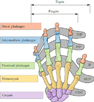
Figure 3.1: Diagram naming the bones in the human hand and wrist. [60] ... 36
Figure 3.2: X-ray showing the three bones that make up the finger. [61] ... 37
x
Figure 3.4: The index finger of the designed hand. Simplified having only
two major parts. ... 38
Figure 3.5: Left, skeleton of the hand. Right, thumb of the hand ... 39
Figure 3.6: The simplified thumb ... 40
Figure 3.7: Left: The skeleton of the human hand [62]. Right: the palm of the human hand ... 41
Figure 3.8: The palm of the designed hand. Left: top of the palm. Right: bottom of the palm. ... 41
Figure 3.9: Some common grasps used.[17] ... 43
Figure 3.10: Assembly of the designed hands fingers ... 45
Figure 3.11: Assembly of the designed hands thumb ... 46
Figure 3.12: Assembly of the palm and knuckles of the hand. ... 47
Figure 3.13: Drive link assembly ... 47
Figure 3.14: Assembly of the thumb and palm of the hand. ... 48
Figure 3.15: Assembly of the servo motors on the top of the palm. ... 49
Figure 3.16: Assembly of the servo motors on the bottom of the palm. ... 50
Figure 3.17: Complete assembly of the hand. ... 51
Figure 3.18: Complete assembly of the hand. Top view. ... 52
Figure 3.19: Diagram assigning reference frames for the D-H convention. [20] ... 53
Figure 3.20: Two link planar manipulator of the designed hand. ... 55
Figure 3.21: Fingertip trajectories in the y-z plane. With the palm being perpendicular to the page and facing towards the bottom of the page. ... 57
Figure 3.22: Fingertip trajectories and the overlapping of the thumb trajectory. ... 58
Figure 3.23: 3D plot showing the trajectories of the thumb and fingertips ... 59
Figure 4.1: Screenshot of the Mindwave mobile core program showing an elevated reading of attention. ... 64
Figure 4.2: Screenshot showing an elevated state of meditation. ... 64
xi
Figure 4.4: The role of the Mindwave mobile in prosthesis control ... 66
Figure 4.5: Simple circuit diagram schematic of the physical set up... 68
Figure 4.6: The process of gripping an object... 69
Figure 4.7: Force sensors on the designed hand ... 70
Figure 4.8: Diagram labelling the bones and joints of the human hand. [70] ... 72
Figure 4.9: Index finger as a two link planar manipulator ... 73
Figure 4.10: Execution of ball grip by designed hand. ... 76
Figure 4.11: Execution of index point by designed hand... 77
Figure 4.12: Execution of pinch by designed hand. ... 77
Figure 4.13: Execution of power grip by designed hand. ... 78
Figure 4.14: Execution of key grip by designed hand. ... 79
Figure 5.1: 3D model of designed hand and dimensions ... 84
Figure 5.2: simplified hand, Palmer view ... 85
Figure 5.3: Simplified hand, top view ... 86
Figure 5.4: Joints and force transferral throughout the finger ... 89
Figure 5.5: Stress plot of proximal phalange index finger ... 92
1
1
Chapter One
1.1
Introduction
The aim of the project is to develop a brain controlled prosthetic hand which can perform the basic functions of a human natural hand. An integrated design approach between mechanics and electronic control, applied to an under-actuated anthropomorphic artificial hand for prosthetic applications will be presented.
Estimates suggest that ten million people on the earth at any one point in time suffer from the effects of a missing limb or body part [1]. Thirty percent of these people are arm amputees that suffer from the loss of either their whole arm or parts of it. Until recent years the development of prosthetic devices that return function and confidence to these upper limb amputees has been very limited. Over the last decade research and development in prosthetics has opened the door to a new age of prosthetics. Never before have we been able to mimic the aesthetics, function and performance of a human hand as we can today.
The mechanical design and electronic control of an artificial anthropomorphic hand requires interdisciplinary research in the fields of electrical engineering, mechanical engineering, computer science, economics and mathematics.
In New Zealand there is a serious gap in the knowledge required for the design and control of anthropomorphic robotic prosthetic hands. This knowledge will only be gained by the research, design and development of these devices in the south pacific.
2
1.2
Motivation
The major contribution of this research is to support the rehabilitation of amputees. A study suggest that three million people on the earth at any one point in time suffer from the loss of an arm or parts of it [1]. One of the major issues for an amputee using a prosthetic limb is the “sense of belonging”. A successful prosthetic gives amputees the feeling that it belongs to them and it becomes an intimate extension of their body. If there exists a “sense of belonging” from the amputee it is more likely that the prosthetic will be successful [2]. The pressing of buttons or performance of a specific posture to get a prosthetic to perform a task makes the amputee feel that the prosthetic hand does not belong to them. Using brain signals to control a prosthetic device will raise the sense of belonging. The research will increase the availability of neural prosthetic devices and encourage the development of functional, dextrous and useful prosthetic devices for upper extremity amputees.
3
1.3
Objectives
The key objectives of this project include the evaluation, design and selection of a prosthetic hand that is controlled by the brain. The research will focus on the electronic control and mechanical design of the proposed hand. To achieve these objectives chapter one introduces the thesis aims, motives and objectives. Chapter two is the literature review which has been separated into two sections based on the ideas introduced in chapter one, which are: prosthetics and robotics. In light of chapters one and two, chapter three explains the mechanical design of the hand. Chapter four discusses the control system of the hand and the development of controlling the prosthetic. Chapter five discusses the performance and aesthetics of the hand and in chapter six conclusions are drawn.
4
1.4
Scope
The scope of this paper is limited to off-the-shelf electrical components due to restrictions in budget, simplicity and availability. These factors justify the need for a simple, inexpensive and easy-to-program prosthetic device. This research is to act as a platform for the development of brain controlled prosthetics at the University of Waikato.
The research will use force sensors to provide simple feedback to the controller. Force sensors are included in the scope of the work because of its direct relation to function and the potential to increase the “sense of belonging” between amputee and prosthetic device.
The mechanical design of the hand will be achieved by the computer aided design program “SolidWorks”. The hand will be based on the skeletal structure of the human hand.
Material choices are limited to the three dimensional printing materials available at the University of Waikato. Limitations associated with the material used for production will be addressed but no effort will be made to minimise the effects of it.
Consideration of other or all types of prosthetics would avail no useful information due to the broad range of amputees and potential pathways towards recovery. The research, analyses, the performance, aesthetics and function of the designed prosthetic hand. The hand has four fingers and an opposable thumb.
The methods used to evaluate the hand will be limited to what is already found in literature. Some of these methods include: trajectory planning, kinematics, velocity kinematics, force evaluation and workspace planning. No new testing methods will be created in the testing of the developed hand. Rather a combination of current testing methods will be employed to analyse the hand in three specific but different areas: Performance, function and aesthetics.
5
2
Chapter Two
The literature relevant to the thesis aim falls into two fields: Prosthetics and Robotics. These two fields are enormous. Therefore the scope of this review is limited to areas of research that are considered relevant to the thesis aim. In the first section the history and challenges associated with prosthetic development are reviewed. In the second section research into the development and control of robots and electromechanical hands is revised. The review is concluded by highlighting the areas of prosthetics and robotics that can be combined to produce and develop a sufficiently dexterous prosthetic hand that can be controlled by the brain.
2.1
Prosthetics
The world around us is built upon the premise that it can be manipulated and changed by the human hand. Everyday activities inevitably involve the use of hand operated tools, devices and utensils. The loss of a limb or parts of it can have a dramatic effect on the quality of life and the emotional stability of individuals.
In the field of medicine a prosthesis is a man-made device that replaces a missing body part. Other sources define prosthesis as devices that are either external or implanted, that substitutes for or supplements a missing or defective part of the body. Throughout literature there is a common theme that prosthetics are devices which aid, give function or restore function to body parts that are missing, not functional or partly functional.[3]
6
Figure 2.1: A render of a futuristic artificial arm [4]
Limb loss most commonly originates from, trauma, disease, congenital condition and injuries suffered through warfare. Prosthetic devices are designed and assembled according to the need of the amputee. Amputee needs vary widely and may be met in multiple ways according to the patients varying need for function. The future of prosthetics is bright. Advances in technology are opening doors to new and superior prosthetics. Figure 2.1 shows an artists prediction of where prosthetics are heading.
2.1.1
History of Prosthetics
Prosthetics in this day are able to mimic the function of a human natural limb more now than in any other time in history. Improvements in technology and understanding of mechanical systems and computer control have opened the door to an exciting age of human like prosthetic devices.
Artificial limbs and prosthetic devices were first realised and used in ancient Egypt where fibre was used to fill the empty cavity of missing limbs.[5] In these times the prosthetic was used purely aesthetically with the intention of making the amputee ‘whole’ or ‘natural looking’. Figure 2.2 shows an artificial toe made from wood. A Prosthetic device dating to around 300 B.C. was found in Italy in 1858. The device was made of bronze, iron and wood and was made for a below knee amputee. There is also an account of a Roman general in the second Punic war (around 218-210 B.C.) who had an arm amputated but returned to war using an iron hand fashioned to hold his shield.
7
Figure 2.2: An early prosthetic toe fashioned from wood. [6]
Little improvement or progression in the field of prosthetics was realised in the dark ages. Most prosthetics at the time were used to hide deformity. Functioning prosthetics were simple and consisted of a hook or peg leg. The use of functioning prosthetics did not progress until the early 1500’s where reports of prosthetic hands claimed that mechanical spring systems were able to manipulate the grip and force exerted by the prosthetic hand.
Prosthetic devices since this time have advanced in many aspects. Prosthetics from the 1500’s till now have employed lighter and stronger materials like plastic, titanium, aluminium and composite materials: each iteration being more effective. In addition to lighter and more durable devices the advent of microprocessors, computer chips and robotic systems is returning higher levels of function to amputees than ever before. Today’s state-of-the-art prosthetic devices combine the latest technology in robotics with multi degree of freedom mechanical systems.
2.1.2
Types of Prosthetics
There are many types of prosthetics used for both function and appearance. Prosthetics are typically divided into four different categories: Joint Prosthetics, Arm Prosthesis, Leg Prosthesis and Cosmetic Prosthesis. An explanation of each type of prosthetic will be given in the following text.
8
2.1.2.1 Joint Prosthetics
Cartilage is a part of the human body that provides padding between bones. When this cartilage becomes worn the bones rub directly on to each other and limit movement. Prosthetics can be suitable replacements for these joints. The most commonly replaced joints are hips, knees and shoulders. Figure 2.3 shows a typical knee replacement.
Figure 2.3: Prosthetic replacement for lower limb amputee above the knee. [7]
2.1.2.2 Arm Prosthetics
Arm prosthetics commonly referred to as upper limb prosthetics are used to replace parts of the arm or the whole arm in some cases. The main types of arm prosthesis are Trans-radial and Trans-humeral. Trans-radial prosthetics are attached below the elbow, while Trans-humeral prosthetics attach to the upper arm (when the elbow joint is missing). Nigel Ackland (Figure 2.4) shown below has a trans-radial prosthetic attached to his arm.
9
Figure 2.4: Nigel Ackland demonstrating the use of his Bebionic prosthetic limb. [8]
2.1.2.3 Leg Prosthetics
There are two types of leg prosthetics (also termed lower limb prosthetics). Trans-tibial prosthetics are used to replace limb loss below the knee and Trans-femoral prosthetics are attached to the upper leg and include the knee joint. Leg prosthetics attempt to return function (ambulation) to amputees by customisation of the prosthetic to the amputees’ needs, finance and health. Figure 2.5 shows a foot prosthetic.
10
Figure 2.5: Prosthetic foot replacement and its aesthetic covering. [9]
2.1.2.4 Cosmetic Prosthesis
These type of prosthetics do not improve function. These are only used to improve appearance. Some common cosmetic prosthetics are artificial eyes, feet, toes, fingers, hands, dentures and dental replacements. These prosthetics are often used to correct facial deformities, disease and trauma. Figure 2.6 shows an array of finger, hand and arm prosthetics that have only cosmetic applications.
11
2.1.3
Complexity versus Function
The complexity of any prosthetic device is interwoven with its ability to function well. A balance between function and prosthetic device complexity is of great importance when developing prosthetic devices. This section introduces ideas applicable to all prosthetic devices, but due to the aim of the thesis, the scope of this section will focus on the limitations associated with prosthetic hands.
“The human hand is a masterpiece of mechanical complexity”[11]. An ongoing challenge for scientists and engineers is imitating the complexity, function and aesthetics of the human hand. The human hand is a complex system [12] capable of accomplishing a wide range of movement with function covering small and precise control (grasping a pen, figure 2.7) to the wielding and grasping of heavy objects with considerable force. The wide range of possible movement the human hand is capable of is not realised in any prosthetic or mechanical device to this day. Finding a balance between complexity and function is the aim of all prosthetic and mechanical hand designers.
12
2.1.4
Degrees of Freedom
Successful prosthetics are often measured according to its ability to use tools in an unmodified human environment. References [14] and [15] suggest that other predictors of prosthetic success are ease of application, function and method of control. In mechanics the degrees of freedom (DoF) of a system is “the number of independent parameters that define its configuration. It is the number of parameters that determine the state of a physical system and is important in the analysis of systems of bodies in mechanical engineering.”[16]. The DoF in a mechanical hand relates directly to its functionality. An increase in DoF for a finger means that the three dimensional workspace of the finger also increases. A relationship exists between the amount of DoF and the physical limitations of the mechanical system being used. The following section describes the limitations of physical workspace with respect to the maximisation of DoF within a hand design.
Reference [17] Claims to obtain a hand that accurately represents the posture and movement of a human hand. It uses a twenty four DoF hand model to measure the required balance between complexity and realism. Figure 2.8 describes the joints of the human hand, these joints account for a single degree of freedom.
13
Figure 2.8: Bones of the human hand act as the basis for most prosthetic kinematic set ups.
Reference [18] Uses the human skeleton (Figure 2.8) of a hand as the basis for a twenty six DoF hand while [19] uses the same structure to model a DoF hand. Reference [14] suggests that the hand can be modelled effectively in twenty two DoF. There is a collective concern that these models cannot be represented as workable physical models due to the limitations of current technology [20]. A major limitation arises with actuator size. In order to model the above mentioned hands an actuator is required per degree of freedom. Twenty six DoF would require twenty six actuators. It is difficult to find actuators that are small and powerful enough to move the fingers and thumb of a prosthetic hand.
The models above are only feasible as computer generated simulations and are not yet representative of a real, self-contained working model of the human hand. Reference [21] explains that current prosthetic fingers have single joint actuators for independent actuation: in these cases the bulky driving mechanisms are an impractical choice for prosthetics due to space limitations. Most self-contained hands have the capacity to hold only a few actuators within the workable space of the hand. Table 1 shows the relationship between the amount of DoF with respect to under-actuation and self-containment. Self-contained in this case means the
14
actuators are mounted within the device workspace and are not driving the fingers from an external position. Table 2.1 lists fourteen electro mechanical prosthetic hands and their respective DoF with relation to amount of actuators and under actuation. The far right column states whether the hand is self-contained or not.
Table 2.1: Comparison of current electro mechanical hands
Hand DOF Actuators
Under-actuated
Self-contained
I-limb 6 DC motor yes Yes
Bebionic 5 DC motor yes yes
Dextrous 6 DC motor yes yes
Robonaut 12 - yes yes
Shadow 20 Air muscle no no
Utah/MIT 15 pneumatic no no
Hitachi 12 Shape Memory
Alloy no no
Rugters 20 Shape Memory
Alloy no no
Belgrade 4 DC motor yes no
Stanford 9 DC motor yes no
NTU 17 Micro-motor no yes
DLR 16 DC motor no yes
Michaelangelo 2 - yes yes
Azzurra 11 DC motor yes yes (Appendix 3 contains an evaluation of the hands presented in this table)
15
In 2002 reference [12] claimed that prosthetic devices in its day were very limited due to the following factors:
- Low grasping capability due to most digits on any hand being individually actuated by one motor.
- Unnatural appearance of grasping movements because of the low number of DoF.
- The lack of sensory information given to the user.
- The lack of intuitive and natural command interfaces that are non-fatiguing and practical to use over a long period of time.
Suggestions to improve in these areas are given by reference [12] and explored by references ([18],[17] and[19]). Reference [22] expresses the following as the key contributors to limitations in prosthetic devices.
- The availability of bidirectional neural interfaces. - Light powerful actuators.
An interesting point is raised with respect to complexity versus function when considering the control of robotic prosthetic hands. Literature in general supports the notion of gaining functionality by increasing the amount of DoF in any prosthetic device; however a rise in DoF increases the complexity of controlling the device. Therefore a balance of complexity and function is required, one cannot be dominant at the expense of the other as they are both essential.
In 2006 participants at the state-of-the-science meeting in prosthetics and orthotics identified a wide range of research priority areas that would ultimately improve the success rate of prosthetic wear. Reference [15] Suggests that control inputs and product development were of the greatest importance at that time. This justifies claims from references [22],[12]and [21] that the control requirements of prosthetic devices failed to adequately meet the mechanical requirements of operation at that time. Since 2006 the control of mechanical hand devices has improved: meaning that the need for mechanical actuators that are light, small and powerful has increased.
16
2.1.5
Abandonment and Success
In response to the aim of this paper to support the rehabilitation of amputees it is vital to understand the reasons for prosthetic abandonment and prosthetic success. The success of prosthetic devices hinges upon the relationship between the designer and the end user. A successful prosthetic becomes an intimate extension of an amputee and as such must qualify and adhere to a high standard of function, quality and aesthetics.
In 2007 reference [23] claimed to have identified some of the factors relating to the abandonment of prosthetics. These factors included: control, age, environment of prosthetic use, cosmetic appearance, functionality, social acceptance, fitting time, lifestyle, gender and hand dominance.
A 1989 survey of upper extremity amputees and prosthetic device success rate claimed the following factors as invalid reasons for prosthetic abandonment: Age, loss of dominant hand, loss of elbow, marital status, use of rehabilitation services, use of a temporary prosthesis and training [24].
Another review of prosthetic success was conducted in 2002 by reference [25]. The review focussed on the limitations of the rehabilitation procedure with respect to electric powered prosthetic devices. The unique approach of the review revealed important factors relating to design theory. Design theory includes the following areas of prosthetic rehabilitation: Comfort, range of motion, component consideration, stabilization, anatomical contouring, cosmetics and suspension. The review concluded that the knowledge of these concepts increases the effectiveness of the rehabilitation and help selecting appropriate control systems, interfaces and componentry for every amputee.
The review of literature in this area is inconsistent. As such it is not easy to claim to have designed a prosthetic device that will be accepted by all. “It remains difficult to sketch a truly reflective picture of the general state of upper limb prosthesis use and abandonment based on the available literature”. [23].
17
2.1.6
Conclusion
This section has reviewed the current limitations, types, complexity and reasons for success of prosthetic devices. There is no simple solution that caters for all amputees. The aim of the paper suggests that a prosthetic hand that is brain controlled will increase the success of prosthetic devices. The following section will review current technology in robotics that can be used in conjunction with the ideas expressed in this section.
18
2.2
Robotics
The previous section has reviewed prosthetics and its relationship with the aim of this paper to develop a brain controlled prosthetic hand. The following section builds upon this knowledge and looks over robotic ideas and principles that can be related to the thesis aim. The ideas expressed in this section are used in combination with the ideas reviewed in the previous section.
“Robotics is a relatively young field in modern technology that crosses traditional Engineering boundaries. Understanding the complexity of robots and their applications requires knowledge of electrical engineering, mechanical engineering, systems and industrial engineering, computer science, economics and mathematics.”[26]
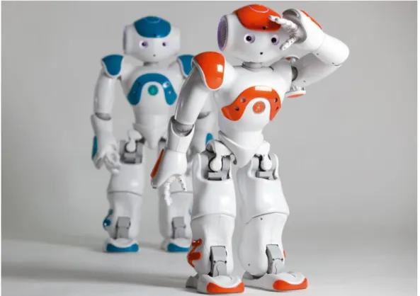
“Robotics is the branch of technology that deals with the design, construction, operation and application of robots” [27]. Robots are mechanical or virtual artificial agents that are usually an electro-mechanical machine that is controlled by a computer program or electronic circuitry. Robots have a wide range of autonomy and in some cases are given human-like characteristics to convey a sense of intelligence or use of agency as shown in figure 2.9.
19
Figure 2.9: Nao the programmable humanoid robot by Aldebaran robotics in France. [28]
The field of Robotics is large and includes many areas that will not be represented in this text. The material covered in this review is only a small amount of a much larger discipline.
2.2.1
History of Robotics
Robotics is a term derived from the word robot which was first used in a play written in the early 19th century by a Czech writer named Karel Capek. His play named “Rossum’s Universal Robots” begins with a factory that produces artificial people. The Slavic word robota is used to describe the artificial creatures. Robota translated into English means labour. Although Capek used the word he named his brother Josef as the words originator. The word robotics was then used in text by Isaac Asimov in an original publication named “Liar!” and is generally cited as where the word originates.[29].
20
2.2.2
Structure and Classification of Robots
Robot mechanisms and manipulators are classified by different criteria. Some of these criteria include their power source, actuation of joints, geometry, kinematic structure and method of control [26]. The classification of robots is useful in determining the correct application for a specific robot. The following section describes the typical structure and classifications of the majority of robots on the market.
2.2.3
Power source
Robots are generally powered electrically, hydraulically or pneumatically. Each power source is an asset in some instances but has its limitations in other circumstances. For example a DC motor is a good fit for small, quiet and cheap applications such as a toy car, whereas a hydraulically powered system would be too loud and unclean. In the case of foundry robots the most sensible choice would be to use hydraulics because of its ability to lift heavy loads. Pneumatically powered robots are cheap but not well suited to precision applications without the help of control systems to control the energy of the system. Figure 2.9 shows an electrically powered cheetah.
21
2.2.4
Application Area
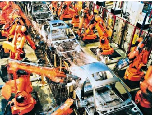
It is common to classify robots into assembly and non-assembly robots. This classification is accepted generally due to the increased need for factory and assembly robots. The area of application is dependent upon the robots power source and its intended use. Figure 2.11 gives an example of multiple assembly robot arms used to produce vehicles.
Figure 2.11: An assembly line using assembly robots to complete the welding of car chassis. [31].
2.2.5
Method of Control
Robots are generally classified as servo or non-servo robots. Non-servo robots are limited to predetermined mechanical stops while servo robots are more complex and involve controlling the method in which the end effector is manipulated in real space. The simplest servo robot in this class is called a point-to-pointrobot. These robots are limited to a discrete set of points. The pathway of the end effector between the taught points cannot be controlled and therefore the applications for such robots are very limited. ‘Continuous path’robots control the path of the end effector from start to finish. There is however a more complex control unit needed to control a ‘continuous path’ robot. It is most desirable to have a continuous path robot in many instances due to the wide range of applications and the ability of the robot to be taught new tasks.
22
2.2.6
Geometry
Most assembly and non-assembly robots have less than six DoF. These robots can usually be defined by one of five kinematic configurations. The configurations are: Articulate (RRR), Spherical (RRP), SCARA (RRP), Cylindrical (RPP) and Cartesian (PPP).
2.2.7
Quantification of Prosthetic Hand Performance
The human hand can be used in a variety of ways to manipulate the physical world. In order to quantify the complex hand configuration and movement of a human hand there first needs to be a common definition of a human grasp. After an in depth analysis of grasp taxonomy reference [20] claims that the lack of a general definition of human hand grasp stems, from the mingling of multiple disciplines defining the human grasp as something that fits conveniently into their field of expertise. The following text explains this giving specific examples. Reference [22] defines an acceptable grasp as a hand that can exert 35 N of force upon grasping whereas reference [11] focuses on finger placement as the definition of a successful grasp. Each approach is correct in their respective fields of engineering and computation however each field lacks important elements of grasping.
In consideration of hand performance the following sources [32-36] each defined a list of human hand grasps as a reference for comparison. Prosthetic hands were rated on how well they mimicked the human hand grasps in their reference. In each article different references were used and therefore a myriad of results were produced, even for the same artificial hands. Methods of comparison also varied greatly. Reference [33] identified multiple methods of comparison when quantifying the performance of artificial hands. Some of these comparison methods are: shape matching, calculation of end effector trajectories, dimensionality reduction and control algorithms.
In the case of this paper grasping will be “every static hand posture with which an object can be held securely with one hand, irrespective of the hand orientation”[20]. This review will only consider one handed grasps and will not include gravity dependant grasps. In cases where hand orientation is limited by the contents of an object (for example a glass of water) the definition still applies.
23
In 2013 reference [37] set forth a detailed analysis of anthropomorphic prosthetic hands. Their report analysed the mechanical characteristics of the following hands: iLimb, iLimb Pulse, Bebionic, Bebionic v2 and the Michelangelo hand. The factors considered in the review included: finger design, kinematics, joint coupling, actuation methods, weight, size, DoF and developer differences. The review compared quantifiable factors common throughout each hand and ranked each hand according to its effectiveness in that particular area.
Throughout literature there are viable methods of quantifying individual areas of artificial hand performance but there is no standard at which to compare prosthetic hands in general. In review of [37-50] it is apparent that each hand is designed to be functional and aesthetically pleasing, however, there is no way of adequately ranking the general performance of one hand to another because of the vast differences in: developer aims/goals, intended use of hand and consumer needs. To this point in time there is no literature claiming to have found any decisive factors that fully contribute to prosthetic device success with the exception of age and the presence of additional physical limitations in amputees.
2.2.8
Analysing Methods
The methods of analysing the functionality, performance and aesthetics of prosthetic hands are wide ranging and in most cases use complex mathematic algorithms, equations and processes. A few of these methods will be described and analysed.
2.2.8.1 Kinematics
Kinematics is part of the mechanical study of motion it helps describe the motion of points, bodies and systems of bodies. Kinematics does not consider the cause of motion, rather it describes the possible motion of kinematic chains given certain parameters [51]. A kinematic chain is a series of rigid bodies connected by joints. Understanding kinematic chains are vital because a human hand can be represented as a number of separate kinematic chains supported on the palm of the hand [20]. Each finger can potentially be a single kinematic chain with the joints of the hand being the joints of the chain.
24
Forward kinematics is the process where kinematic equations are used to describe the position of an end effector with the knowledge of joint angles and linkage lengths. Reverse kinematics operates in the reverse order where end effector position is given to find joint angles and linkage lengths.
The Denavit-Hartenberg formalism is used to simplify the process of predicting the position of links in the kinematic chain with reference to a frame chosen to reduce the amount parameters needed to describe the chain.
2.2.8.2 Velocity Kinematics
In the previous section the kinematic equations were used to determine end effector trajectories and positions under given conditions. In this section the end effector or any part of the manipulator is related to the joint velocities. The velocity analysis of the hand will be examined by use of the Jacobian manipulator and the grasp matrix. [26] Describes the Jacobian as a matrix valued function that is involved with determining the following in robot manipulators and mechanical devices.
- Planning and executions of smooth trajectories - Derivation of the dynamic equations of motion - Execution of coordinated anthropomorphic motion
- Transformation of forces and torques from the end effector to the manipulator joints
2.2.8.3 Jacobian Manipulator
The Jacobian manipulator also called the Jacobian is used to relate the linear and angular velocities of the end effector of a robot manipulator to the joint velocities of the said manipulator. The forward kinematics describe a function between the space of Cartesian positions and orientations with the space of joint positions [26]. The Jacobian of this function then determines the velocity relationship between joints, positions and orientations. The Jacobian is represented by the letter J and is a matrix valued function. Comprehensive detailing of the processes involved in this method can be found in. [26]
Suppose there is 𝑚 equations for end effectors and each has an 𝑛 amount of degrees of freedom. We can write.
25 𝑥1 ⋮ 𝑥𝑚 = 𝑥1(𝛼1,…,𝛼𝑛) ⋮ 𝑥1(𝛼1,…,𝛼𝑛) ( 1 0 )
Deriving the above equation yields.
𝑑𝑥1 𝑑𝑡 ⋮ 𝑑𝑥𝑚 𝑑𝑡 = 𝛿𝑥1 𝑑𝛼1 𝑑𝛼1 𝑑𝑡 + ⋯ + 𝛿𝑥1 𝛿𝛼𝑛 𝑑𝛼𝑛 𝑑𝑡 ⋮ 𝛿𝑥𝑚 𝛿𝛼1 𝑑𝛼1 𝑑𝑡 + ⋯ + 𝛿𝑥𝑚 𝛿𝛼𝑛 𝑑𝛼𝑛 𝑑𝑡 ( 1 1 )
Re-writing in vector form gives.
𝑣 = 𝐽𝑑𝑎
𝑑𝑡 ( 1 2 )
The Jacobian is now seen as
𝐽 = [ 𝛿𝑥1 𝑑𝛼1 ⋯ 𝛿𝑥1 𝛿𝛼𝑛 ⋮ ⋱ ⋮ 𝛿𝑥𝑚 𝛿𝛼1 ⋯ 𝛿𝑥𝑚 𝛿𝛼𝑛] ( 1 3 )
The Jacobian of a two link planar manipulator is shown below
Here the Jacobian is.
𝐽 = [−𝑙1 𝑠𝑖𝑛 ∝1− 𝑙2 𝑠𝑖𝑛(∝1+∝2) − 𝑙2 𝑠𝑖𝑛(∝1+∝2)
𝑙1 𝑐𝑜𝑠 ∝1 + 𝑙2 cos (∝1+∝2) 𝑙2 cos (∝1+∝2) ] ( 1 4 )
26
2.2.8.4 Trajectory Planning/Shape Matching
In order to mimic the human hand the movement of an artificial hand must look natural and move in a way that does not draw attention to itself. Trajectory planning is an analysis method used to compare the trajectory of an artificial finger with the movement of a human finger. In order to execute trajectory planning successfully there are multiple factors that need to be considered. These factors are: joint velocity, joint acceleration, torque (in the case of revolute joints) and position. Successful trajectories match the shape and form of human hand movement and are quantified by shape overlap.
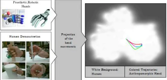
2.2.8.5 Dimensionality Reduction
Dimensionality reduction explained in reference [33] is the process in which prosthetic device performance is quantified by recording human hand movements and projecting them onto a two dimensional space (figure 2.12) using a linear reduction algorithm. The movements of an artificial hand are then projected onto the same space, the overlap is used as the basis for comparison.
Figure 2.12: Projection of prosthetic hand workspace in comparison to a human hands natural workspace. [33]
27
Figure 2.13: Action manifolds of a human in comparison with two robots. [33]
[20] Defines “action manifold” (Figure 2.13) as the postures a hand can reach. The action manifold can represent all the postures a hand can reach or any subset of those postures. The action manifold varies widely as the kinematic setup of the artificial hands change. Once sufficient action manifolds have been recorded and reduced to two dimensions it can be represented as a two dimensional shape with associated area. Artificial hands are then considered anthropomorphic if the two dimensional shape produced from its action manifold considerably overlaps the human action manifold. In the figure above “Robot 1” has a larger action manifold, however it is considered less anthropomorphic than “Robot 2” because its overlapped area with the “Human” action manifold is smaller. “Robot 1” could have a larger area because: it has more DoF, of a larger amount of individual actuators or a larger amount of available configurations. Each of these reasons increase dimensionality.
There are benefits to using dimensionality reduction. In each case a configuration of the human hand is used as reference, this reference configuration can be representative of the performance of the whole hand or an accurate reflection of an individual configuration. An artificial hand that is capable of fine movements may be highly anthropomorphic when referencing to an action manifold of fine human motor skills but score poorly when subjected to a reference that only considers gross motor skill. Dimensionality reduction can take into account the general performance of an artificial hand as well as the task specific orientations needed for individual tasks.
28
2.2.9
Latest Technology
2.2.9.1 Neural Interface
The field of biotechnology is growing at a rate where new areas of study are constantly created. One such area is neural engineering. Neural engineering combines the disciplines of neurophysiology, electronic engineering and mechanical engineering [52]. Neural engineering is the key to linking brain activity to man-made machines and devices with the intention of restoring sensory and motor function to amputees and patients with neural disorders.
A neural interface (figure 2.14) is used to record brain activity with the intention of using it to control a mechanical device or computer simulation. Brain activity produces signals which are detectable on the surface of the scalp [53]. These signals are translated into a useable signal that can be used to communicate a user intention without the use of natural communication methods such as peripheral nerves and muscular interactions.
29
“Brain controlled interfaces (BCI) are devices that capture brain transmissions involved in a subject’s intention to act, with potential to restore communication and movement to those who are immobilized.”[52].Neural prosthetics are devices that are used to associate transmitted brain signals with physical movements.
Reference [53] suggests two main types of brain controlled interfaces: invasive and non-invasive. As the names suggests non-invasive BCI are inclusive of headsets and external devices that can pick up emitted signals from the brain. Current non-invasive BCI use electroencephalography. Invasive BCI are directly linked to the brain by implantation, surgery and other similar methods.
Reference [52] recognizes the four main types of methods used to acquire useful brain signals.
- Electroencephalography (EEG) - Electrocorticography (ECoG) - Local field potentials (LFPs)
- Single-Neuron action potential recordings.(single units)
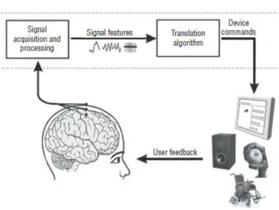
Whatever method is employed the processing of brain signal remains constant. Emitted brain signals are acquired through a BCI, the signal is then translated into a useable command signal. The command signal is then used to control a mechanical device. The user then processes the information and changes input signal according to the current state of the mechanical device being controlled. The following section will briefly touch on the basic ideas involved with electroencephalography. The research only looks at this method of acquiring brain signals due to time limitations and project scope.
2.2.9.2 Electroencephalography
Electroencephalography is the recording of electrical activity non-intrusively along the scalp. The process involves monitoring an individual cell in the brain called a neuron for action potential. An action potential is an electrical impulse produced from the neuron and is what neurons use to communicate with each other. The electrical impulses represent information. Recording neuronal interaction produces signals that can be compartmentalised to represent a specific desire of the person who is subject to the recording. Figure 16 conveys how a common spike in the
30
generated signal can be interpreted as the subjects desire to turn left. (Figure 2.15) A lack of these spikes could also be used as a signal from the user to turn right.
Figure 2.15: data analysis of a potential "turn left" signal [55]
Recording more neurons increases the amount of information that can be analysed and interpreted. Figure 2.16 conveys the process of acquiring and using brain signals to control mechanical devices.
Figure 2.16: Common method of acquiring and using brain signals to control a mechanical device. [53]
Reference [53] identifies some of the limitations of invasive BCI. These limitations are substantial technical difficulties, the risks of surgery, no guarantee the device will function well for extended periods of time and brain damage. Successful
non-31
invasive studies include the controlling of emitted brainwaves to move a robotic arm, move a computer mouse and select programs in a two dimensional frame and moving a mouse in a three dimensional frame.
2.2.9.3 Sensory Feedback
An ongoing challenge for scientists and engineers is to copy the sensory motor function of the human hand. Reference[12]claims prosthetic hands in our modern day exhibit common limitations in sensory motor functions due to mechanical, aesthetic and sensory feedback limitations. Until recently sensory feedback to amputees has been limited to visual observation and sounds emitted from prosthetic devices.
Reference [56] explains the processing of sensory information as a cyclic procedure rather than a linear sequence. “Although it is customary to think of behaviour as a linear sequence of sensing, analysing, and acting, this is not the case. When animals are in motion, they are constantly probing the environment, sensing changes and using the information to generate the next action. This is a continuous cycle rather than a linear sequence, with sensation directing output and altering sensory input.”
There are four stages of receiving sensory information (Figure 2.17) and four sensory receptors used to detect the type of energy input to the system or body. The four stages are: reception, transduction, transmission and perception. The types of sensory receptors used in receiving sensory information are: mechanoreceptors, chemoreceptors, electromagnetic receptors, thermos-receptors and pain receptors. [56]
32
Figure 2.17: Display of the four receptors found in the human skin. [57]
The cyclic procedure of obtaining and using sensory feedback has been examined by reference [12] concluding that technological advances in recognising the perceived changes in the peripheral nervous system will open pathways of returning sensory information to the user. In 2013 reference [58] identifies two methods of providing amputees with sensory feedback: modality matched feedback and sensory substitution. Experimentation found that modality matched feedback was achievable; however they were too big, expensive and consumed a lot of power. Sensory substitution is low cost, low power and easy to integrate, it is however a substitute and the “sensation” or “feeling” created by touching is eliminated. Responsibility for these issues has been accredited to the limitation of technology in neural interfaces and the timing of the feedback. [59]
33
2.2.10
Conclusion
An effective and successful prosthetic hand involves the combination of prosthetic knowledge and applications with the automation and technical capabilities of robotics. This chapter has addressed important aspects of robotics that can be directly used in the world of prosthetics. The chapter has been focussed on upper extremity amputees with the intent of responding to the thesis aim of developing a brain controlled prosthetic hand. Understanding the limitations of current technology and the physical limitations of actuation methods in robotics is essential in the mechanical design of a functional prosthetic hand. A successful prosthetic must have a good balance between complexity and function. In the following chapter the mechanical design of the hand will be addressed with relation to the ideas expressed in this chapter. A functional hand is fundamental and necessary to the design of a brain controlled prosthetic hand. Sufficient time and consideration has been given to the mechanical design of the hand.
35
3
Chapter Three
The previous chapter has reviewed current theory and considered the latest knowledge in the design and development of brain controlled prosthetics. A large portion of this research has been dedicated to the development of a functional and dexterous mechanical hand. The physical design of the hand is expressed in this chapter. The hand expressed in this chapter is controlled by signals emitted from the brain. The method of control is explained in chapter four.
3.1
Mechanical Design
In light of chapter two the mechanical design of a prosthetic hand will be discussed. This chapter will explain the design method used to design a functional prosthetic hand. Important ideas that will be discussed are:
- The design simplifications - The degree of under actuation - The driving mechanism of the hand - The mechanical assembly of the hand
- The kinematics and path planning of the fingers.
The hand is capable of five grasps/gestures and will be analysed on its ability to perform the grasps and gesture in a timely manner and with sufficient force.
36
3.2
Skeletal simplifications
Reference [19] Explains the anatomical model of the hand (including the wrist) as consisting of forty five muscles acting to engage twenty joints in the hand. The joint geometry defines a need for twenty DoF to mimic the movement of the natural human hand. Reference [20] presents the human hand to be made up of twenty seven bones as shown in figure 3.1.
Figure 3.1: Diagram naming the bones in the human hand and wrist. [60]
The natural complexity of the human hand necessitates simplification when attempting to mechanically replicate functions of the human hand.
The following simplifications will decrease complexity in design and increase the effective movement/control of the designed hand.
37
- The metacarpal bones (excluding the thumb metacarpal) and the entire set of carpals will be combined to make up one part in the designed hand representing the palm.
- The middle and distal phalanges on each finger will become one part representing the end of the finger.
- Proximal phalanges on each finger will be driven by individual actuators and the end of the finger will be coupled by a rigid link.
- The thumb Metacarpal will be driven by a single actuator and the remaining bones in the thumb will be actuated by another individual actuator.
Mechanical simplicity facilitates the electronic control of the hand but it can decrease the hand dexterity. Finding a balance between simplification and dexterity is of great importance and should be considered in the design of all prosthetic hands.
The mechanical replication of the human hand necessitates simplification. In this section the relationship between the designed hand and the natural human hand will be explained. The fingers, thumb and palm have been simplified.
(Additional drawings of the hand can be found in appendix 2)
3.2.1
Fingers
The human fingers consist of three bones: the proximal phalange, the intermediate phalange and the distal phalange. These bones can be seen clearly in figure 3.2 In order to simplify the finger of the human hand the middle and distal phalanges on each finger are one part representing the end of the finger. Figure 3.3 shows a picture of the index finger.
38
Figure 3.3: The human index finger consisting of three main parts
As seen in figure 3.4 the proximal phalange exists as the main driver of the finger while the distal and intermediate phalanges are rigidly connected. A link between the servo motor and middle phalange drives the middle and distal phalanges while the proximal phalange is directly driven by the actuator. This coupled mechanism imitates the natural grasping motion of the human hand well.
Each finger is simplified in this manner as shown in figure 3.4. The function of the designed hand is not significantly affected by this simplification and the ability of the hand to grasp is adequate for the scope of this work.
Figure 3.4: The index finger of the designed hand. Simplified having only two major parts.
39
3.2.2
Thumb
The thumb is an important appendage to the hand. It is capable of high levels of
function including fine motor control for precision grips and gross motor control
for power grips. The mechanical design of a prosthetic thumb is complex. The
thumb is designed to have the most function of any part of the designed hand and
as such is driven by two servo motors. The thumb is capable of flexion, extension,
adduction and abduction. The thumb will be simplified by taking away its ability to
radially abduct and adduct. This simplification allows space in the palm of the hand
for servo motors. The thumb consists of three bones: the metacarpal, the proximal
phalange and the distal phalange as shown in figure 3.5.
40
From figure 3.6 it can be seen that there is a mechanical part representing each bone
in the thumb. The simplification of this appendage arises from space limitations in
the palm of the hand. This simplification means radial adduction and radial
abduction movements are excluded from the hands motion. The thumb Metacarpal
will be driven by a single actuator in the palm (not shown in figure 3.6) and the
remaining bones in the thumb will be actuated by another individual actuator based
in the metacarpal part of the thumb.
Figure 3.6: The simplified thumb
3.2.3
Palm
The palm of the human hand naturally has thirteen bones inclusive of all carpal and metacarpal bones. The palm serves as a base for the fingers and thumbs. Figure 3.5 shows an x-ray of the human hand and the palm of the human hand.
41
Figure 3.7: Left: The skeleton of the human hand [62]. Right: the palm of the human hand
The metacarpal bones (excluding the thumb metacarpal) and the entire set of carpals will be combined to make up one part in the designed hand representing the palm. The palm is designed as a rigid base to support the fingers and thumb.
On the top of the palm four recesses (figure 3.6) are used to mount the servo motors used to actuate each finger. The bottom of the palm is designed to hold the fifth servo motor and the wires from all the motors. The sixth motor is mounted to the corresponding metacarpal part. A cover protecting the bottom of the palm has been designed. Servo motors on the top of the hand are unprotected and visible.
Figure 3.8: The palm of the designed hand. Left: top of the palm. Right: bottom of the palm.
42
3.3
Under actuation
Under actuation in mechanical devices is a circumstance where the number of actuators in the mechanism is less than the number of total DoF [63]. In the case of robotic anthropomorphic hands the likelihood of being under actuated is very high. From the research of twelve robotic hands [37-50] only four had an equal amount of actuators as DoF. In these cases space for mounting actuators became a challenge and some actuators have to be external to the hand meaning the device was no longer self-contained. In the eight remaining cases each hand varied in degree of under actuation. Under actuation simplifies control and maximises the use of available space.
3.4
Grasping
The tasks of grasping, gripping and holding are studied by many. From one hundred and forty seven sources [32] suggests that human grasps can only be simplified to seventeen different grasp types. Each of the seventeen grasps can be further separated into two different classes relating to two thumb positions: adducted and abducted. [35] Considers five main prehensile grasp types: cylindrical, fingertip, palmar, spherical and lateral where each grip is named relative to the type of object being grasped. Other sources [32-34, 36] approach grasp classification in alternate manners. Figure 3.7 shows some examples of common grasps.
43 Figure 3.9: Some common grasps used.[17]
This project will study five grasps/gestures. These grasps are: key grip, power grasp, pinch, ball grip and index point. These five grasps/gestures only represent a small amount of the possible grasps types but are sufficient to test the designed hands feasibility of being a successful prosthetic.
Material choice is limited to a material named “Vero White” which can be described as a rigid opaque photopolymer. The material properties can be found in reference [64]. This choice of material is based upon project costs, available 3D printed materials and time constraints.
44
3.5
Driving Mechanism
A simple driving mechanism will be employed to actuate the fingers and thumb of the hand. Reference [65] tests the feasibility of using shape memory alloys as an actuator for a prosthetic hand. After study the shape memory alloys proved successful however the process is highly dependent on temperature and a specially designed power amplifier had to be designed to ensure proper actuation. Project time restraints did not accommodate further investigation of this actuation method. Other actuators considered include: Piezoelectric actuators[66], pneumatic actuators [67] and DC motors.
Servo motors were selected as the actuator for the designed hand. The Futaba S3114 micro servo provides the torque required for the hand to operate. Useable force is transferred through to the fingertip by rigid links. The driving mechanism converts linear motion to rotational motion through a series of couplings.
3.6
Assembly
The hand consists of twenty six 3D printed parts and various electronic components. This section describes the assembly of the fingers, thumb, palm, knuckles, electronics and hand in its entirety. Each of the mechanical 3D printed parts require water-blasting, cleaning and removal of excess support material before assembly.
3.6.1
Fingers
Each finger of the hand is based on the design of the index finger. The directions for the assembly of the index finger will be displayed here. The remaining fingers can be assembled in the same manner.
The fingers consist of four mechanical 3D printed parts, two link pins and one M3 bolt and one M3 nut. Figure 3.8 shows the assembly of the fingers.
- The base of the proximal phalange is inserted into the knuckle by “snap” fit. - The index link is placed inside the proximal phalange and one link pin is
45
- The inter-distal phalange is separated and placed on each side of the top end of the proximal phalange.
- The other link pin is inserted through the inter-distal phalange, proximal phalange and the top end of the link.
- The assembly is completed by the bolting together of the inter-distal phalange through the bolt hole situated where the distal interphalangeal joint would be.
Figure 3.10: Assembly of the designed hands fingers
3.6.2
Thumb
The thumb is made up of four 3D printed parts and four M2 bolts and nuts. Figure 3.9 shows the assembly of the thumb.
- The metacarpal part serves as a base for the thumb.
- The base of the proximal phalange is mounted to the metacarpal part through the provided bolt holes and tightened.
- The thumb link is placed through the proximal phalange and fixed to the back of the metacarpal part by another bolt and nut.
46
- The distal phalange is bolted to the top of the proximal phalange and the top of the thumb link through two different bolt holes and tightened.
47
3.6.3
Palm and knuckles
The palm of the hand is designed as a base for the fingers and thumb. On the top side of the palm are four identical areas designed to fit the finger assembly. As shown in figure 3.12 the full assembly of the fingers fit into the areas provided leaving room for the mounting of the servo motors. Figure 3.13 shows the assembly of the drive link assembly.
Figure 3.12: Assembly of the palm and knuckles of the hand.
48
3.6.4
Thumb and palm
Once the thumb is assembled it can be mounted to the bottom of the palm. Figure 3.14 shows the assembly of the thumb and palm.
- The top of the metacarpal part of the thumb is placed in the recess in the palm where the gear can fit just below the knuckle of the index finger.
- The bottom of the metacarpal part is placed in the semi-circular recess where the wrist bones would connect to the palm.
- The palm cover is placed over the bottom of the palm and fitted firmly into place.
49
3.6.5
Electronic Assembly
The assembly of the electronics is completed in two parts: assembly of the finger servo motors and assembly of the thumb servo motors. This section will only convey the assembly of the servo motors used to actuate the fingers and thumb of the hand. Figure 3.15 shows the electronic assembly.
When the palm and knuckle are assembled there are small compartments designed for the mounting of servo motors in the top of the palm. The assembly of the finger servo motors is simple.
- The motors are placed in the compartments provided and bolted down with the servo horn end placed farthest from the fingers.
- Wires are placed through the bottom of the hand by the holes opening directly through the palm.
Figure 3.15: Assembly of the servo motors on the top of the palm.
50
3.6.6
Thumb Servo Motors
The thumb requires two servo motors to be functional. The first motor is responsible for the adduction and abduction movement of the thumb, the second motor is used to put the thumb in extension and flexion. Figure 3.16 shows the assembly of the thumb servo motors.
- The first motor is place in the bottom side of the palm with the bolt arms of the servo fitting into the purpose built recess below the middle finger. - The second motor is mounted to the metacarpal part of the thumb and bolted
directly to the part.
(bolting of this second motor must be done before the thumb assembly is mounted to the palm.)
Figure 3.16: Assembly of the servo motors on the bottom of the palm.
The wiring from each of the servo motors are gathered and placed in the cavity produced between the palm cover and th
![Figure 2.1: A render of a futuristic artificial arm [4]](https://thumb-us.123doks.com/thumbv2/123dok_us/504607.2559531/21.892.193.657.94.348/figure-render-futuristic-artificial-arm.webp)
![Figure 2.4: Nigel Ackland demonstrating the use of his Bebionic prosthetic limb. [8]](https://thumb-us.123doks.com/thumbv2/123dok_us/504607.2559531/24.892.331.604.89.499/figure-nigel-ackland-demonstrating-use-bebionic-prosthetic-limb.webp)
![Figure 2.17: Display of the four receptors found in the human skin. [57]](https://thumb-us.123doks.com/thumbv2/123dok_us/504607.2559531/47.892.181.671.95.429/figure-display-receptors-human-skin.webp)
![Figure 3.1: Diagram naming the bones in the human hand and wrist. [60]](https://thumb-us.123doks.com/thumbv2/123dok_us/504607.2559531/51.892.167.679.336.898/figure-diagram-naming-bones-human-hand-wrist.webp)
![Figure 3.2: X-ray showing the three bones that make up the finger. [61]](https://thumb-us.123doks.com/thumbv2/123dok_us/504607.2559531/52.892.175.780.872.1060/figure-x-ray-showing-bones-make-finger.webp)
