®
EMULEX
3545 Harbor Boulevard
MDOI
(MEDALIST) DISK CONTROLLER TECHNICAL MARUAL
Costa Mesa, California 92626 (714) 662-5600 TWX 910-595-2521
energy, and if not installed and used in accordance with the technical manual, may cause interference to radio communications.
It has been tested and found to comply with the limits for a Class B computing device pursuant to Subpart J of Part 15 of the
Federal Communications Commission (FCC) Rules, which are designed to provide reasonable protection against such interference when operating in a residential installation. However, there is no guarantee that interference will not occur in a particular installation.
Copyright (C) 1984 Emulex Corporation
The information in this manual is for information purposes and is subject to change without notice.
Emulex Corporation assumes no responsibility for any erro'rs which may appear in the manual.
TABLE OF CONTENTS
Section
ONE GENERAL DESCRIPTION
1.1 1.1.1 1.1.2 1.2 1.3 1.3.1 1.4 1.4.1 1.4.2 1.4.3 1.4.4 1.4.5
INTRODU CT ION • II • • • • 0 II • • • 0 0 • • • • 0 • • • 0 • 0 • • 0 0 0 • • 0 • • • • • • • • 0
RELATED DOCUMENTS • 0 0 Q Q • • • 0 " • • • • • • • • • 0 • • • • • • • 0 • • • • • •
TECHNICAL MANUAL CONVENTIONS .•••••••.••••.•..•••.•. PHYS I CAL DESCRIPTION •••••••••••••••••••.•...•.•.•...•
FUNCTIONAL OVERVIEW •• 0 0 0 " • • • • 0 0 0 • • • 0 0 • • • 0 • II • • • • • 0 • 0 0 •
FEA T{J RES 0 0 0 0 0 • 0 0 II • • 0 • • II 0 • • 0 • • 0 • 0 It • 0 • 0 • • 0 0 • • • • • 0 • • 0 0 CO M PA T I B I L I TY C I . . . 0 • • 0 • 0 • • 0 • • • • • • • • • • • • • • • • • • • • 0 • • • • 0 •
SCSI BUS HARDWARE COMPATIBILITy .•.••••..•.••.••.•.. SCSI BUS PROTOCOL AND COMMAND COMPATIBILITY ••••••.•
SCSI COMMAND SET •• 0 0 • • • • 0 • • • • • • • • • • • • • • • • • • • • • • • • • •
DEVIATIONS FROM SCSI STANDARD •.••.•••••.•.•••••.... ST506 DISK DRIVE INTERFACE COMPATIBILITY •••••••..•.
TWO MDOI CONTROLLER SPECIFICATIONS
2.1 2.2 2.3
OVERV lEW 0 0 • • 0 0 0 • • • • 0 0 • • • • • • • 0 • 0 • • • • • • • • • II • • • • • • • • • • • •
GENERAL AND ELECTRICAL SPECIFICATIONS ••••.•.••..••.•. PHYS I CAL SPECIFI CATIONS ••••••••••••••..•••••••.••••.•
THREE INSTALLATION
3.1 3.1.1 3.2 3.3 3.3.1 3.3.2 3.3.3 3.3.4 3.3.5 3.3.6 3.3.7 3.3.8 3.3.9 3.4 3.5
aVE RV lEW 0 0 0 0 • 0 0 0 0 0 0 0 0 • • • • • • • o· 0 0 • • 0 0 0 0 0 0 0 0 • • 0 • • • • • 0 0 • 0
DIP SW ITCH TY PE S 0 0 0 0 • • 0 0 0 0 0 • 0 • • • 0 • • • • 0 • • • • • • • • • • • • •
INS PE CT I 0 ~l 0 \) 0 • 0 0 0 0 0 0 0 0 0 • • 0 • 0 0 • • " • • 0 Ii • • • • 0 0 • • • 0 • • • 0 • • •
MDOI SCSI CONTROLLER SETUP •••••.••••••••••••••.•.•••• ENCODED DR IVE TY PE •••••••••••••••••••••••••••••••••
S ECTO R S I Z E • 0 0 0 0 0 0 0 " • 0 0 0 0 0 • • 0 0 • • • • 0 • 0 • • • 0 • • • • • • • • • •
c
P{J S PE ED 0 0 0 • • • 0 a 0 • • 0 • 0 • • • " • • • 0 • • • • • • 0 • • • • • • 0 • • • • • •SCSI DEVICE ADDRESS SELECTION ••.•••••••••••••••••••
EPROM SELECTION 0 0 • • • 0 . 0 • • • • • • • ~ • • • • • • • • • • • • 0 • o • • • 0 .
NUMBER OF SPARE SECTORS PER TRACK .••••••.•••••••••• BUFFERED STEP OPTION ••..•••••••••••••••••••••... DRIVE CONFIGURATION SOURCE .•••.•••••••.•••..•••••.• SCS I TERMINATION OPTION •••.••••.•••.••.•••.••.•.•.. MDOI SCSI CONTROLLER INSTALLATION ..•••••••••.••••.•••
FCC COMPL IAN'CE 0 " 0 0 • • • 0 • • 0 0 • 0 0 • • 0 • • 0 • 0 • • • • • • • • 0 • • 0 • • 0 •
FOUR TROUBLESHOOTING
4.1 4 .1.1 4.2 4.3
OVERV lEW ••• 0 • 0 0 0 0 0 • 0 0 0 • 0 0 0 • • • • 0 • • • 0 • 0 • • • • • • 0 • • • • • 0 • 0 •
SERV ICE . 0 0 0 I» 0 • 0 . . . 0 • • • • • • • • 0 •
POWER-UP SELF-TEST ••• 0 0 • o. 0 • • 0 • • If • • • • • • • • • • • • 0 • • If • 0 • •
ON-LINE DIAGNOSTIC SUBCOMMANDS ...•.••••.•.•.•••.•..
5.2 5.2.1 5.2.2 5.2.3 5.3 5.3.1 5.3.2
MD01 CONTROLLER ARCHITECTURE 8031 MICROPROCESSOR ••••• DISK FORMATTER •••••••••• BUFFER CONTROLLER
. .
.
.
.
.
.
.
.
. .
. .
. .
.
. . .
.
.
.
.
. .
.
. .
.
.
. .
.
.
.
••
DISK OPERATIONS ••••••••
·
.
.
.
.
.
.
.
.
. .
.
.
.
.
. .
. .
.
.
TRACK FORMAT OPERATIONS ••••BAD SECTOR FORMAT OPERATIONS
·
· .
.
.
.
. .
.
.
.
.
.
. .
.
. .
.
. .
. .
.
.
.
.
.
.
SIX INTERFACES6.1 6.2 6.2 •. 1 6.2.1.1 6.2.1.2 6.2.2 6.2.2.1 6.2.3 6.2.3.1 j.2.3.2 6.3 6.4 SEVEN 7.1 7.2 7.3
OVERVIEW
.
.
.
.
. .
.
.
.
.
. .
. .
.
. . . .
.
. . . .
. .
. .
.
.
. .
.
. . .
.
.
.
.
.
.
. .
.
SCSI BUS INTERFACE. .
.
.
.
. .
. . .
. .
. . . .
.
. .
.
.
.
.
.
.
.
.
.
. .
. .
.
SCSI BUS INTERFACE PHYSICAL DESCRIPTION Cable Requirements •••••••••••••••••
Shielded Cable Requirements ••••••••
...
SCSI INTERFACE ELECTRICAL DESCRIPTION ••••••••••••••Terminator Power (Optional) ••
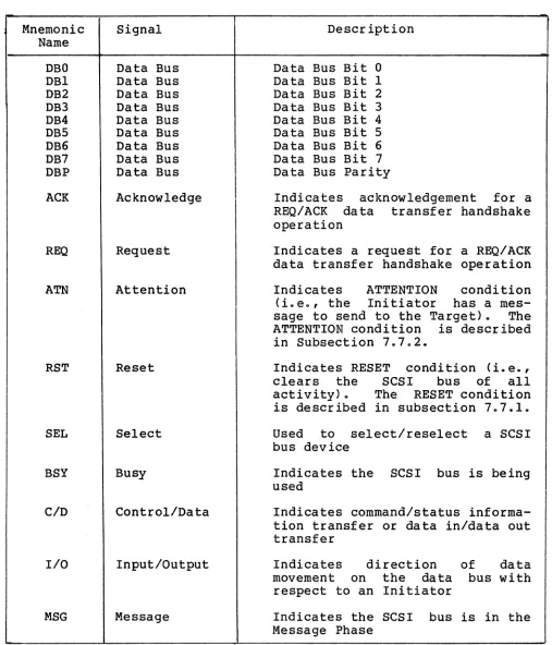
SCSI BUS SIGNALS AND TIMING ••••••
...
·
.
.
.
.
.
.
.
. .
SCSI Bus SignalsSCSI Bus Timings
. . .
.
. .
.
.
.
.
. .
.
. .
. .
.
. .
.
.
. .
.
.
. . .
. .
. .
.
.
. . .
.
.
. .
.
.
. .
. . .
.
.
. .
. . .
.
.
.
. .
. .
.
MD01 CONTROLLER USER'S PANEL CONNECTION •••••••••••••• ST506 DISK DRIVE INTERFACE.
. .
. .
. .
. .
.
.
. . . .
.
. . .
. .
.
.
.
.
.
.
SCSI BUS PROTOCOL
OVERVIEW ••••••••••••
.
. .
.
. . .
.
.
.
.
.
.
.
.
.
. .
.
SCSI BUS DESCRIPTIONSCS I BUS PHASES
.
.
.
.
. .
. .
.
.
.
.
.
.
.
.
.
.
.
.
. .
. . .
.
. . .
.
.
. . .
.
.
. .
ARBITRATION PHASE •••••••••••••••••.
.
.
.
.
.
.
.
.
.
SELECTION AND RESELECTION PHASES ••••••••••••••••••• INFORMATION TRANSFER PHASES • • •·
... ·
.
Command Phase ••••••••••••••• • ••••••••••••• Da ta Phase ••.•.•••.•••••••.•••••••••••• • ••••••• status Phase •.••••.••••••••••••••••••••• • •••• Status Byte Format ••••••••••••••••••••••••••• Me ssa ge Phase .••••••••••••• • • • • • • • • • • • • • •••• 7.3.1 7.3.2 7.3.3 7.3.3.1 7.3.3.2 7.3.3.3 7.3.3.3.1 7.3.3.4
7.4 SCSI BUS PHASE SEQUENCING •••••••••••••••••••••••••••• 7.5 SCSI MEMORY ADDRESS POINTERS ••••••••••••
· ... . ...
7.6
7.7 7.7.1 7.7.2
SCSI COMMAND QUEUING •••••••• SCSI BUS CONDITIONS
RESET
ATTENTION
.
.
EIGHT MDOI SCSI COMMAND SET
8.1 OVERVIEW ••••••••••••••••••••••••••••••••••• 0 • • • • • • • • •
8.2 8.3 8.3.1 8.3.1.1
SCSI COMMAND DESCRIPTOR BLOCK STRUCTURE •••••••••••••• SCSI GROUP CODE 0 COMMAND DESCRIPTIONS •••••••••••••••
8.3.1.2 8.3.1.3 8.3.4.1 8.3.1.4.1 8.3.1.4.2 8.3.1.4.3 8.3.2 8.3.2.1 8.3.3 8.3.3.1 8.3.4 8.3.4.1 8.3.4.2 8.3.5 8.3.5.1 8.3.5.2 8.3.5.3 8.3.6 8.3.7 8.3.7.1 8.3.8 8.3.9 8.3.10 8.3.10.1 8.3.10.2 8.3.10.3 8.3.11 8.3.12 8.3.13 8.3.14 8.3.14.1 8.3.14.2 8.3.14.3 8.3.14.3.1 8.3.14.4 8.3.14.5 8.3.15 8.3.16
COpy •••••••••••••••••••••••••••••••••••••••••• D • • • •
Random-to-Sequentia1 Access and Sequential-to-Random Access Copy Operations •••••••••••••••••• Random-to-Random Access Copy Operations ••••••••• Sequentia1-to-Sequentia1 Access Copy
Operations . o o • • • • • • • • • • • • • • • • • • • • • • • • • • • • • • • • • q
Error and Other Conditions During a Copy
Ope r a ti on •••••••••••••••••••••••• 18 • • • • • • • • • • • " •
End-of-Media Condition •••••••••••••••••••••••• File Mark Condition ••••••••••••••••••••.•••••• Incomplete Condition •••••••••••••••••••.•••••• FOR!JIAT UNIT ••••••••••••••••••••••••••••••••••••••• Format Unit Data Format ••••••••••••••••••••••••• INQUIRY ••••• a • • • • • • • • • • • • • • • • • • • • 0 • • • • • • • • • • • 0 • • • •
Inquiry Data Format ••••••••••••••••••••••••••••• MODE SELECT • . 0 . • • • • • • • • • • • • • • • • a 0 • • • • • • • • • • • • • • • • 0
Mode Select Parameter List for ESDI Disk
Drives ... 0 • • • • • • • • • • • • • • • • • • • • • • • • • • • • • • • • • • • • •
Mode Select Parameter List for ST506 Disk
Drives . . . .
MODE SENSE • 0 • • • • • • • • • 0 • • 0 • • • • • • 0 0 • • • • • 0 a • • • • • • • • • •
Mode Mode Mode Sense Sense Sense Data Data Data Format Format Format
• • • • • 0 0 • • • • • • 0 • • • • • • • • • • • •
for ESDI Disk Drives ••••• for ST506 Disk Drives •••• READ •••••••••••••• 0 . . . 0 • •
RE-ASSIGN BLOCK ••••••••••••••••••••••••••• ,. . . . .
Re-assign Block Data Format ••••••••••••••••••••• RECEIVE DIAGNOSTIC ••••••••••••••••••••••••••••••••
REL EAS E UN IT. • • • • • • • • • • • • • • • • • • • • • • • • • 0 • • • • • • • • • 0 •
REQUEST SENSE •••• 0 • 0 0 • • • • • • • • • • • • • • • • • • • • • • • • • • • • •
Standard Sense Byte Format •••••••••••••••••••••• Extended Sense Byte Format •••••••••••••.•••••••• Vendor-Unique Extended Sense Byte Format •••••••• RESERVE UNIT •••••••••••••••••••••••••••••••••••••• REZ ERO UNIT ••••••••••••••••••••.••••••••••••••••••
SEEK ••••••••••••••••••••• 0 • • • • • • • • • • • • 0 • • " • • • • 0 • • •
SEND DIAG NOSTIC ••••••••••••••••••••••••••••••••••• PERFORM DRIVE DIAGNOSTIC •••••••••••••••••••••••• READ BAD SECTOR FILE ••••••••..•••••••••••••••••• READ DISK PARTITION ••••••••••••••••••••••••••••• READ DISK PARTITION Data Format •••••••••••••.• READ LONG •••••••••• 0 • • • • • • • • 0 • • • • • • • • • • • • • 0 • • • • 0
WRITE LONG •••••••••••••••••••••••••••• 0 • • • • • • • • •
TEST UNIT READY • 0 • • • • 0 • • • 0 • • • • 0 • • • • • • 0 • • • • • • • • • • • •
WRI TE ••••••••• 0 • • • 0 • • • • • • • • • • • • • • • • • • • • • • • • • • • • • • •
8.4 SCSI GROUP CODE 1 COMMAND DESCRIPTIONS •••••••••••••• 8.4.1
8.4.1.1
READ CAPACITY ••••••••••••••••••••••••••••••••••••• Read Capacity Data Format •••••••••••••••••••••••
Table 1-1 2-1 2-2 3-1 3-2 3-3 3-4 3-5 4-1 4-2 6-1 6-2 6-3 6-4 7-1 7-2 8-1 8-2 8-3 8-4 8-5 8-6 8-7 Figure 1-1 1-2 3-1 3-2 3-3 3-4 4-1 5-1 5-2 6-1 6-2 6-3 6-4
LIST OF TABLES
Title
00001 SCSI Command Set ••••••••.•••••••••••••••••••••• General and Electrical Specifications ••••••••••••••• Physical Specifications ••••••.••.•.••••••••••••••••• DIP Switch Settings, 00001 SCSI Controller .•••..•.•.• Disk Drive Configuration Table Entries •••••••••••••• Parameters for Entries in Disk Drive Configuration
Table G O O Q 0 0 0 a 0 0 • 0 0 0 0 . 0 0 • 0 0 • a 0 • • • • • • 0 0 • • • • • • It • • • • • • •
SCSI Device Address Selection Switches •.•••••••••... Number of Spare Sectors/Track •••••••••••••••••.••.•• LEO Test Code Oescriptions D • • • • • • • • • • • • • • • • • • • • • • • • •
00001 Controller Diagnostic Subcommands ••••.••••••••• SCSI Bus Signals ••••••••.••••••••••.•••••••••••••••• Pin/Signal Assignments at SCSI Bus Interface •.•••••. SCS I Bus Timings 0 • • • • • 0 • • • • • • • • • • • • • • • • • • • • • • • • • • • • •
External LEDs Connector Pin Description ••••••••••••• S tat us Co de s 0 0 • 0 • 0 0 • 0 0 • 0 0 0 • 0 • • 0 0 • 0 0 0 • 0 • • • 0 0 • • • • 0 0 0 • •
00001 SCSI Messages •••••••••••••••••••••••••••••••••• COpy Command Function Codes •••••.•••••••.••••••••••• MDOI Controller Format Modes ••••••••••.•••.•••••••.. Spare Sector s/Tr ack Bits •••••••••••••••••••••••••••• READ Command Error Conditions .••.•••••.•••.••••••••• Standard Sense Error Classes ••.•.••••••••••••••••••• Standard Sense Byte Error Codes •••••••.•••.••••••••. Sense Key Error Codes •••••••••••••••••••••••••.•••.•
LIST OF FIGURES
Title
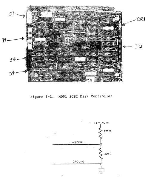
00001 (Medalist) Disk Controller •••..••••••.••.•••••• Sample SCSI Bus System Configuration ••••.••••••••••• 00001 Switch and Jumper Locations •••••••••••••••••••• Installing MDOI Controller on Mounting Bracket •••••• Connecting Disk Drive Data and Control Cables to
00001 Controller ••.••••••••••••••••.••••....•.•••••• Connecting SCSI Bus to 00001 Controller ••••..•.•.•••. Location of LEDs on MOOI Controller •••.••.•••••.•••. 00001 SCSI Controller Block Diagram •••.•.•...•••..••• 00001 Controller Disk Header Format •..••••••••••..••• 00001 SCSI Disk Controller ••••..••••••..•••.••••.••.• SCSI Bus Signals Termination •..•..•.••••••••••...•.. SCSI Bus Timing Diagram •••••.•••••..•.•.••..•.•..•.• Control Pin/Signal Assignments at ST506 Disk
Drive Interface ••••.•••••••.•••.••••.•.•••.•....•.• 6-5 Data Pin/Signal Assignments at Disk Orive
7-1
7-2 8-1 8-2
In t e r face
0... 0 . 0 . . .
Sample SCSI Bus Configurations •••••••••••.•.••••••.• SCSI Bus Phase Sequences ••••••••.••••••••••••••••••• Sample Group 0 Command Descriptor Block •••••••••.•.• Sample Group 1 Command Descriptor Block ••••.•.•••••.
CONTROLLER WARRANTY: Emulex warrants for a period of twelve (12) months from the date of shipment that each Emulex Controller Product supplied shall be free from defects in material and workmanship.
During this period, if the customer experiences difficulties with an Emulex controller and is unable to resolve the problem via the phone with Emulex Technical Support, a Return Authorization will be issued. Following receipt of a Return Authorization, the customer is respon-sible for returning the product to Emulex, freight prepaid. Emulex, upon verification of warranty will, at its option, repair or replace the controller in question, and return to the customer freight prepaid.
CABLE WARRANTY: All Emulex provided cables, not included as part of a subsystem, are warranted for ninety (90) days from the time of shipment. Questionable cables should be returned to Emulex, freight prepaid, where they will be repaired or replaced by Emulex at its option and returned to the customer freight prepaid.
The above warranties shall not apply to expendable components such as fuses, bulbs, and the like, nor to connectors and other items not a part of the basic product. Emulex shall have no obligation to make repairs or to cause replacement required through normal wear and tear or necessitated in whole or in part by catastrophe, fault or negli-gence of the user, improper or unauthorized use of the Product, or use of the Product in such a manner for which it was not designed, or by causes external to the Product, such as but not limited to, power failure or air conditioning. Emulex's sole obligation hereunder shall be to repair or replace items covered in the above warranties. Purchaser shall provide for removal of the defective Product, ship-ping charges for return to Emulex and installation of its ieplacement.
RETURNED MATERIAL: Warranty claims must be received by Emulex within the applicable warranty period. A replaced product, or part thereof, shall become the property of Emulex and shall be returned to Emulex at Purchaser's expense. All returned material must be accompanied by a RETURN AUTHORIZATION number assigned by Emulex.
section 1 GENERAL DESCRIPTION
The MDOI SCSI Disk Controller, called the Medalist, was designed by
Emu~ex Corporation to interface Small Computer System Interface
(SCSI) hosts and controllers to one or two ST506 5 1/4-inch Winchester disk drives. (The SCSI bus can interface with up to eight host adapters and/or related microcontroller devices.) This manual is designed to help you install the MDOI Controller and to provide information about buffering, signal translation capabili-ties, and applications. The contents of the eight sections are described briefly below.
Section I General Description: This section contains an overview of the MDOI Controller.
Section 2 MDOI Controller Specifications: This section contains specifications for the major components of the MDOI Controller.
section 3 Installation: This section contains the information nec-essary to install the MDOI Controller in your system. Section 4 Troubleshooting: This section describes diagnostic
procedures that can be used to pinpoint problem areas on the MDOI Controller.
Section 5 Functional Description: This section describes the architecture and disk operations of the MDOI Controller. Section 6 Interfaces: This section describes the SCSI bus and
ST506 disk drive interfaces.
Section 7 SCSI Bus Protocol: This section describes the SCSI bus protocol, including signals, phases, and timing.
For reference convenience, Section 1 is divided into four subsections, as listed in the following table:
Subsection Title
1.1 Introduction
1.2 Physical Description 1.3 Functional Overview 1.4 Compatibility
1.1.1 RELATED DOCUMENTS
This manual is designed to be used by system programmers who are writing operating system drivers and support utilities. Familiarity with the SCSI standard and the ST506 disk drive interface specification are assumed.
The SCSI command set for the MDOI Controller is based on the ANSI X3T9.2/82-2 Rev. 14 (24 April 84) SCSI Specification. As the SCSI standard is currently changing, this ANSI specification is subject to change without notice. It is the intent of Emulex to maintain SCSI compatibility as the standard evolves.
The ST506 interface standard for 5 1/4-inch Winchester disk drives is described in standard #XXXXXXXXXX.
1.1.2 TECHNICAL MANUAL CONVENTIONS
To avoid possible confusion with other uses of the same words, throughout this manual we use the following conventions~
• All SCSI commands (such as READ, MODE SELECT, and INQUIRY) and diagnostic subcommands (such as READ BAD SECTOR FILE and
WRITE LONG) are printed in uppercase boldface.
• All SCSI status and error messages (such as CHECK CONDITION and DRIVE NOT READY) are printed in uppercase.
• All SCSI bus phases and conditions (such as Arbitration Phase) and SCSI Command Descriptor Block names (such as Extended Sense Byte) are printed in initial caps.
Physical Description
102 PHYSICAL DESCRI~TION
The MDOI Controller, shown in Figure 1-1, is assembled on a single board (approximately 5 3/4-inches by 8-inches) and is installed directly on a mounting bracket located in the subsystem that contains an ST506 5 1/4-inch Winchester disk drive. The MDOI Controller contains two Emulex custom Very Large Scale Integration
(VLSI) chips; one is a Buffer Controller and one is a Disk Formatter. It also contains an 8031 microprocessor chip, a 16-kilobyte Electrically Programmable Read Only Memory (EPROM), and a l6-kilobyte Random Access Memory (RAM) which provides 10 kilobytes of data buffering.
[image:11.618.168.485.339.590.2]1.3 FUNCTIONAL OVERVIEW
In combination with an independent host adapter, the SCSI bus allows a wide variety of computers to interface with the MDOI Con-troller. Compatible computers include DEC systems that use the Q-bus and UniQ-bus, IBM Personal Computer systems like the IBM PC/XT, and Intel Multibus-based computers. Up to eight bus devices, in any combination of host systems and intelligent controllers, can be supported by the SCSI bus. The MDOI Controller, in combination with one or two ST506 5 1/4-inch Winchester disk drives, provides a low-cost, compact, storage subsystem in a microcomputer environment.
The MDOI Controller's architecture and supported SCSI features make i t an ideal building block for use by O.E.M.s and system integrators. The MDOI Controller supports a powerful set of SCSI commands. By using those commands, an efficient Multi-Initiator configuration can be constructed with the support of the Disconnect function. (The Disconnect function allows the MDOI Controller, when it is performing a time-consuming task, to release the SCSI bus temporarily and reconnect at a later time when the task is complete.) The MDOI Controller may be considered a SCSI extended-bus device because all standard and extended SCSI commands are used.
Emulex currently offers two additional SCSI bus microcontrollers that can be used with SCSI bus subsystems: the Titleist and the Champion. The Titleist Tape Controller interfaces the SCSI bus to Cipher 540 Cartridge Tape Drives. The Champion Disk Controller interfaces Enhanced Small Disk Interface (ESDI) 5 1/4-inch disk drives to the SCSI bus.
In addition to basic stand-alone controller products, Emulex also offers complete SCSI bus disk and tape packaged subsystems for microcomputer applications.
A sample configuration of a SCSI system is shown in Figure 1-2.
HOST HOST
CPU ADAPTER
i3
ST506CII..----"
ESCI
Compatibility
1.3.1 FEATURES
The MDOI Controller features are summarized below. More details on these features are given in subsequent sections.
• SCSI Implementation based on ANSI X3T9.2/ 82-2 Rev 14 (24 April 84) Specification
• Support of standard 5 1/4-inch Winchester Disk Drives with ST506 interfaces
• Powerful SCSI command set including: -Common Commands
-Random Access Device Commands
-COpy Command
-Linked Command Support
• Support of Disconnect/Reconnect Function • Command Queuing from multiple Initiators • Hard Reset
• Buffered operation to optimize performances • Extensive self-test and diagnostic facilities
• Compatible with Emulex's ESDI disk controller and Cipher 540 tape controller
There are two Dual In-Line Package (DIP) switch packs on the MDOl Controller. Both switch SWI and switch SW2 are eight-pole general control switches used for configuring various disk parameters. For configuration details, see Section 3 (Installation).
1.4 COMPATIBILITY
Compatibility of the MDOI Controller with ST506 disk drives and SCSI host adapter systems and related microcontrollers is described in the following subsections.
1.4.1 SCSI BUS HARDWARE COMPATIBILITY
The MDOI Controller supports the SCSI single-ended bus option. The
overall length of the cable that connects the SCSI host adapters
and controllers in a daisy-chained manner can extend to 6 meters.
All SCSI signals in the cable are terminated at each end by
terminating resistors of 220 Ohms to +5 Vdc, and 330 Ohms to
ground. Terminators are optionally installed, and depend on the
physical profile of the SCSI bus (e.g., they would be installed if
the MDOI Controller is used in an environment that includes an
Emulex subsystem as the last device attached to the SCSI bus
cable). The MDOI Controller complies with the FCC limits for a
Class B computing device (see subsection 3.5).
1.4.2 SCSI BUS PROTOCOL AND COMMAND COMPATIBILITY
The MDOI Controller contains an on-board SCSI protocol
control-ler that controls SCSI protocol and the SCSI bus. The MDOI
Controller supports the SCSI arbitration and reselection
capabilities, and data bus parity. The MDOI Controller
supports all standard SCSI commands described in the ANSI
X3T9.2 SCSI specification. For more information on commands
supported by the MDOI Controller, see Section 8.
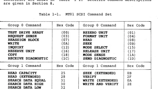
1.4.3 SCSI COMMAND SET
The hexadecimal codes for the SCSI
Controller are shown in Table 1-1.
are given in Section 8.
commands supported by the MDOI Detailed command descriptions
Table 1-1. MTOl SCSI Command Set
Group 0 Command Hex Code Group 0 Command Hex Code
TEST DRIVE READY ( 00) REZERO UNIT ( 01)
REQUEST SENSE (03) FORMAT UNIT (04)
REASSIGN BLOCK (07) READ (08)
WRITE ( OA) SEEK ( OB)
INQUIRY ( 12) MODE SELECT (15 )
RESERVE UNIT ( 16) RELEASE UNIT (17)
COpy (18) MODE SENSE ( lA)
RECEIVE DIAGNOSTIC (lC) SEND DIAGNOSTIC (lD)
Group 1 Command Hex Code Group 1 Command Hex Code
READ CAPACITY 25 SEEK (EXTENDED) OB
READ (EXTENDED) 28 VERIFY 2F
SEARCH DATA EQUAL 31 WRITE (EXTENDED) OA
SEARCH DATA HIGH 30 WRITE AND VERIFY 2E
[image:14.623.27.552.409.705.2]Compatibility
1.4.4 DEVIATIONS FROM SCSI STANDARD
When the MDOI Controller performs the COpy command, it does not
support Copy operations where both the source and destination
Logical Units (LUNs) are on different controllers; however, it does support the third-party reservation needed for the Copy operation.
Since the Copy operation may only be used between LUNs with
compatible block sizes, the MDOI Controller supports block sizes of 256 or 512 byte blocks for external devices.
Commands from several Initiators are queued within the MDOI
Controller. These commands may include the RESERVE UNIT command
(see Table 1-1). If a second command is received from the same
Initiator, and is directed towards the same LUN, the MDOI
Controller returns a BUSY completion status.
1.4.5 ST506 DISK DRIVE INTERFACE COMPATIBILITY
The MDOI Controller can be connected to any ST506 5 1/4-inch
Winchester disk drive via a 34-pin IDC connector reference
designated PIon the MDOI Controller, and one or two 20-pin IDC
male connector reference designators J3 and J4 on the MDOI
Controller. The MDOI Controller was designed specifically for use
2.1 OVERVIEW
Section 2 MOOl SCSI CONTROLLER SPECIFICATIONS
This section contains the general, electrical, and physical specif-ications for the components on the MDOI Controller. A general des9ription of each component is included under FUNCTIONAL in the General and Electrical Specifications table. For a detailed description of the MDOl Controller's function as a whole, see Section 5, Functional Description. The general, electrical, and physical specifications for the MDOI Controller are described in separate subsections as listed in the following table.
Subsection Title
Overview 2.1
2.2 2.3
General and Electrical Specifications Physical Specifications
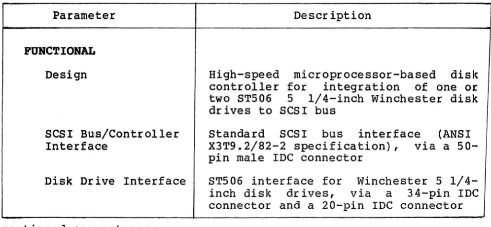
2.2 GENERAL AND ELECTRICAL SPECIFICATIONS
Table 2-1 lists and describes the general and electrical specifica-tions for the MDOl Controller.
Table 2-1. General and Electrical Specifications
Pafameter Description
FUNCTIONAL Design
SCSI Bus/Controller Interface
Disk Drive Interface
continued on next page
High-speed microprocessor-based disk controller for integration of one or two ST506 5 1/4-inch Winchester disk drives to SCSI bus
Standard SCSI bus interface (ANSI X3T9.2/82-2 specification), via a 50-pin male IDC connector
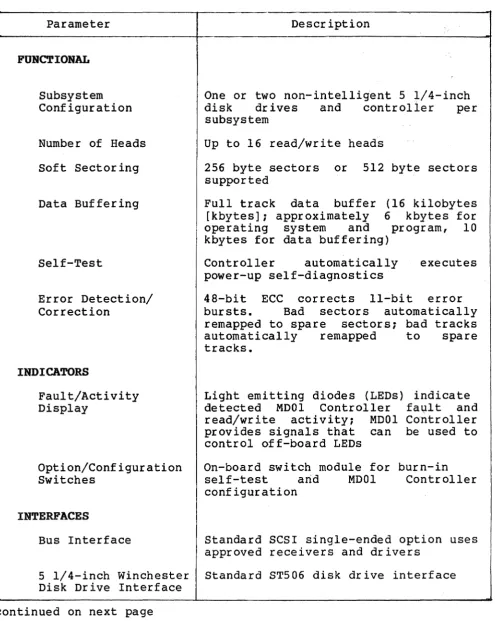
[image:17.613.63.561.465.695.2]Table 2-1. General and Electrical Specifications (continued)
Parameter Description
FUNCTIONAL
Subsystem Configuration
Number of Heads Soft Sectoring
Data Buffering
Self-Test
Error Detection/ Correction
INDICATORS
Fault/Activity Display
Option/Configuration Switches
INTERFACES
One or two non-intelligent 5 1/4-inch disk drives and controller per subsystem
Up to 16 read/write heads
256 byte sectors or 512 byte sectors supported
Full track data buffer (16 kilobytes [kbytes]; approximately 6 kbytes for operating system and program, 10 kbytes for data buffering)
Controller automatically executes power-up self-diagnostics
48-bit ECC corrects II-bit error bursts. Bad sectors automatically remapped to spare sectors; bad tracks automatically remapped to spare tracks.
Light emitting diodes (LEOs) indicate detected MODI Controller fa~lt and read/write activity; MODI Controller provides signals that can be used to control off-board LEOs
On-board switch module for burn-in self-test arid MODI Controller configuration
Bus Interface Standard SCSI single-ended option uses approved receivers and drivers
5 1/4-inch Winchester Standard ST506 disk drive interface Disk Drive Interface
[image:18.615.41.537.103.725.2]Physical Specifications
Table 2-1. General and Electrical Specifications (continued)
Parameter Description
ELECTRICAL
Power +S Volts direct current (Vdc) , ± S%, 1.S Amperes (A) nominal
2.3 PHYSICAL SPECIFICATIONS
Table 2-2 lists and describes the phYSical specifications for the MODI Controller.
Table 2-2. PhYSical Specifications
Parameter Description
Packaging Single board, S 1/4-inch footprint, S 3/4-inch by a-3/4-inch
Cabling Single 20-conductor, radial data cable and daisy chained 34-conductor control cable Mounting Mounts on a mounting bracket contained in
3.1 OVERVIEW
Section 3 INSTALLATION
This section describes the step-by-step procedure for installing
the MDOl Controller, including switch setting data and physical
installation instructions. This installation procedure is divided
into five subsections, as listed in the following table:
Subsection Title
3.1 Overview
3.2 Inspection
3.3 MD01 Controller Setup
3.4 MD01 Controller Installation
3.5 FCC Compliance
If you are unfamiliar
procedure, we recommend beginning.
3.1.1 DIP SWITCH TYPES
with the MD01 Controller installation
reading this Installation Section before
DIP switches used in this product may be either of two types:
Slide SWitch:
To place a slide switch in the ON position, slide the switch in the direction marked ON
or CLOSED. To place a slide switch in the
OFF position, slide the switch in the
direction marked OFF or OPEN.
Piano Switch:
To place a piano switch in the ON position,
move the switch toward the ON or CLOSED
position. To place a piano switch. in the
OFF position, move the switch toward the
OFF or OPEN position.
Switch-setting tables in this manual use numeral one (1) to
3.2 INSPECTION
Emulex products are shipped in special containers designed to provide full protection under normal transit conditions. Immediately upon receipt, the shipping container should be inspected for evidence of possible damage incurred in transit. Any obvious damage to the container, or indications of actual or probable equipment damage, should be reported to the carrier company in accordance with instructions on the form included in the container.
Unpack the MDOI Controller and verify that all components listed on the shipping invoice are present. Verify that the model or part number (PiN) designation, revision level, and serial numbers agree with those on the shipping invoice. These verifications are important to confirm warranty. If evidence of physical damage or identity mismatch is found, notify an Emulex representative immediately.
A visual inspection of the MDOI Controller is recommended after unpacking. Specific checks should be made for such items as bent or broken connector pins, damaged components or any other visual evidence of physical damage. Carefully examine all socketed components to ensure they are firmly and completely seated.
3.3 MDOl SCSI CONTROLLER SETUP
MOOI SCSI Controller Setup
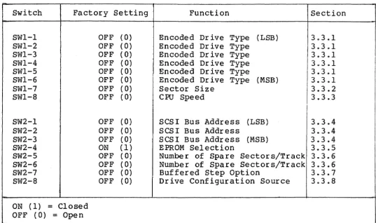
Table 3-1. DIP Switch Settings, MDOI SCSI Controller
Switch Factory Setting SWl-l SWl-2 SWl-3 SWl-4 SWl-5 SWl-6 SWl-7 SWl-8 SW2-1 SW2-2 SW2-3 SW2-4 SW2-5 SW2-6 SW2-7 SW2-8
ON (1) = Closed OFF (0)
=
OpenOFF (0) OFF (0)
OFF (0)
OFF (0)
OFF (0)
OFF (0)
OFF (0)
OFF (0)
OFF OFF OFF ON OFF OFF OFF OFF ( 0) ( 0) (0 ) (1) ( 0) ( 0) ( 0) ( 0) Function
Encoded Drive Type (LSB) Encoded Drive Type
Encoded Drive Type Encoded Drive Type Encoded Drive Type
Encoded Drive Type (MSB) Sector Size
CPU Speed
SCSI Bus Address (LSB) SCSI Bus Address
SCSI Bus Address (MSB) EPROM Selection
Number of Spare Sectors/Track Number of Spare Sectors/Track Buffered Step Option
Drive Configuration Source
Section 3.3.1 3.3.1 3.3.1 3.3.1 3.3.1 3.3.1 3.3.2 3.3.3 3.3.4 3.3.4 3.3.4 3.3.5 3.3.6 3.3.6 3.3.7 3.3.8
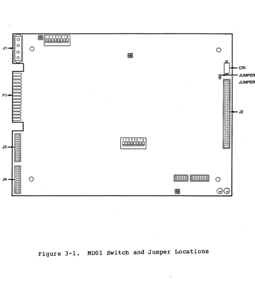
Figure 3-1 shows the locations of the configuration switches, connectors, and jumpers referenced in the subsections below. The configuration switches should be set before the MDOI Controller and the disk drive are installed in a subsystem because the switches may not be accessible after the MDOI Controller/disk drive unit is
[image:23.615.53.590.117.435.2]0 0
~
..
CRI
JUMPER J
JUMPER K
P1
..
..
..
..
J2..
..
..
.
.
. .
.. .. .. .. ..
~
..
..
..
..
..
..
..
J3
.. ..
..
..
..
..
~
J4
..
0/I· .... ·n u
...
... n
....
0.. ..
~..
GG
[image:24.629.42.539.148.697.2]~IDOI SCSI Controller Setup
3.3.1 ENCODED DRIVE TYPE (SWl-l:SWl-6)
If switch SW2-8 is ON (closed), switches SWl-l through SWl-6 are
used to specify disk drive parameters. The switch settings specify
a location in a table located in the firmware on the MDOI
Control-ler. This table, called the Disk Drive Configuration Table,
contains a list of all the disk drives currently supported by the
MDOI Controller. Each disk drive entry in the table is associated
with definitions of five parameters for that disk drive. The five
parameters (and their corresponding mnemonic representation) are
listed below.
• Last Sector Number/Track (LSN) This parameter specifies
the last sector number on the track. Since the sectors are
numbered starting at zero, the last sector number/track
parameter is equal to the total number of sectors/track less one.
• Last Track Address (LTA) - This parameter specifies the last
track address on the disk drive. Since the heads on the
disk drive are numbered starting at zero, the last track
address parameter is equal to the total number of heads on
the disk drive less one.
• Last Cylinder Address (LeA) This parameter specifies the
last cylinder address on the disk drive. Since the
cylinders on the disk drive are numbered starting at zero,
the last cylinder address parameter is equal to the total
number of cylinders on the disk drive less one.
• write Precompensation Cylinder Number (WPC) - This parameter
specifies the number of the cylinder at which the disk drive
will write data to disk using a time-precompensated form.
The time-precompensated form is necessary for Write
operations to inner cylinders (cylinders located near the
center of the disk) where data is stored at a higher density
than the density at outer cylinders. At inner cylinders, a
magnetic effect (called peak shifting) occurs which is
caused by the tendency of closely spaced flux reversal
domains to migrate physically away from each other into
areas of lower density. In the time-precompensated form,
flux reversals that would tend to be shifted late due to
magnetic interference are written early, and those that
• Reduced Write Current Cylinder Number (RWCl - This parameter specifies the number of the cylinder at which the disk drive will supply a different amount of current to the head during a Write operation. The write current supplied to a selected head is not the same for all cylinder locations. More current is supplied for a Write operation on an outer cylinder than is supplied for an Write operation on an inner cylinder. If the write current is not reduced when writing on inner cylinders, flux saturation occurs. This action reduces frequency response and increases data interference
(called crosstalk).
The disk drive entries (that specify those disk drive types supported by the MDOI Controller) contained in the Disk Drive Configuration Table are listed in Table 3-2.
Table 3-2. Disk Drive Configuration Table Entries
Switch
SWl-6 SWl-5 SWl-4 SWl-3 SWl-2 SWl-l Disk Drive Type Config.
MSB LSB Entry t
0 0 0 0 0 0 Maxtor xt-lOOO 1
(256 byte sectors)
0 0 0 0 0 1 Maxtor xt-lOOO 2
(512 byte sectors)
Conf ig. Entry t
=
Disk Drive Configuration Table Entry Numbero
=
OFF (OPEN) 1=
ON (CLOSED)MDOI SCSI Controller Setup
Table 3-3. Parameters for Entries in Disk Drive Configuration Table
Configuration Table
Entry Number LSN LTA LCA WPC RWC
1 31 6 2S4H l40H l40H
2 15 6 2S4H l40H l40H
LSN
=
Last Sector Number/Track LTA=
Last Track AddressWPC
=
Write Precompensation Cylinder Number RWC=
Reduced Write Current Cylinder Number H=
hexadecimal value3.3.2 SECTOR SIZE (SWl-7)
The setting on switch SWl-7 indicates the size of the sector on the disk drive. Setting this switch to ON (closed) indicates the sector size on~the disk drive is 256 bytes. Setting this switch to OFF (open) indicates the sector size is 512 bytes.
The sector size is selected by switch SWl-7. Normally, switch SWl-7 is set to OFF, as shown in the following table:
Switch OFF ON Factory
SWl-7 512 bytes 256 bytes OFF 3.3.3 CPU SPEED (SWl-S)
The setting on switch SWl-S indicates the CPU speed of the on-board S03l Microprocessor. Setting this switch to ON (closed) indicates the CPU speed is 12 Megahertz. Setting this switch to OFF (open) indicates the CPU speed is 10 Megahertz.
The CPU speed is selected by switch SWl-S. Normally, switch SWl-S is set to OFF, as shown in the following table:
Switch OFF ON Factory
3.3.4 SCSI DEVICE ADDRESS SELECTION (SW2-l:SW2-3)
Switches SW2-l, SW2-2, and SW2-3 are used to select anyone of
eight possible SCSI bus addresses. This address establishes the
SCSI bus identity of the MDOI Controller in the system. An
Initiator must specify this address to select the MOOI Controller
as a Target device. Switch settings for the eight possible MDOI
Controller Device Address identities are listed in Table 3-4. Make
sure you do not assign the same SCSI Device Address to two separate host adapters or controllers.
Table 3-4. SCSI Device Address Selection Switches
Switch
SW2-3 SW2-2 SW2-l SCSI Device Address
(MSB) (LSB)
0 0 0 00
0 0 1 01
0 1 0 02
0 1 1 03
1 0 0 04
1 0 1 05
1 1 0 06
1 1 1 07
0
=
OFF (OPEN) 1=
ON (CLOSED)3.3.5 EPROM SELECTION (SW2-4)
The setting on switch SW2-4 specifies the memory size of the EPROM
installed on the MOOI Controller. Setting this switch to ON
(closed) indicates the MDOI Controller EPROM has a memory size of
256 kilobytes. Setting this switch to OFF (open) indicates the
MDOI Controller EPROM has a memory size of 128 kilobytes.
The memory size of the on-board EPROM is indicated by switch SW2-4. Normally, SW2-4 is set to ON, as shown in the following table:
Switch OFF ON Factory
~IDOI SCSI Controller Setup
3.3.6 NUMBER OF SPARE SECTORS PER TRACK (SW2-5:SW2-6)
The setting on switches SW2-5 and SW2-6 specify the number of spare sectors per track available on the disk drive. Switch settings for the number of spare sectors per track are listed in Table 3-5.
Table 3-5. Number of Spare Sectors/Track Selection Switches
Switch
SW2-5 SW2-6 Number of Spare Sectors/Track
0 0 0 spares
0 1 1 spares
1 0 2 spares
1 1 3 spares
3.3.7 BUFFERED STEP OPTION (SW2-7)
The setting on switch SW2-7 indicates if the disk drive Step operation (involving the time intervals in which Step signal pulses occur) is or is not to be buffered. Setting this switch to ON
(closed) indicates the Step operation is to be buffered. Setting this switch to OFF (open) indicates the Step operation is is not to be buffered.
The Buffered Step option is selected by switch SW2-7. Normally, switch SW2-7 is set to OFF, as shown in the following table:
Switch OFF ON Factory
SW2-7 Nonbuffered Buffered OFF 3.3.8 DRIVE CONFIGURATION SOURCE (SW2-8)
The Orive Configuration Normally, switch SW2-B is table:
Switch OFF
SW2-B
Source is determined by switch SW2-B. set to OFF, as shown in the following
ON Factory
Switches SWl-l MODE SELECT
command through SWl-7, sw itches SW2-5 OFF through SW2-B
ROTE
If two different types of disk drives (i.e., they do not have the same parameters such as sector size, brand-type, number of sectors/track, etc.) are connected to the same MOOI Controller, the disk drive parameters specified by switches SWl-l through SWl-7 and SW2-5 through SW2-B are not valid.
3.3.9 SCSI TERMINATION OPTION
The SCSI Termination option allows the MOOI Controller to supply +5 Vdc power to the terminators. If the SCSI Termination option is
required, install a #IN5B20 diode at reference designator CRI on the MOOI Controller printed circuit board (PCBA). Also connect a wire-wrap jumper between jumper posts J and K on the MOOI Controller (see Figure 3-1) to supply +5 Vdc for the SCSI bus termination.
If diode leads are diode is in wrong properly.
CAUTION
reversed so that anode of the hole, system does not function
MODI SCSI Controller Installation
3.4 MDOI SCSI CONTROLLER INSTALLATION
To install the MOOI Controller in the disk drive chassis, see
Figures 3-2 through 3-4 and use the following procedure:
1. Configure MOOI Controller. This action involves setting the
switches on switch packs SWI and SW2 before installing the
MOOI Controller on the mounting bracket in the subsystem
that contains the disk drive(s). All switches have been set
at factory; however, you may need to reset certain switches
to satisfy your specific needs.
2. Place disk drive subsystem on flat surface.
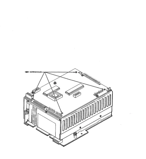
3. Place MOOI Controller (component side up) on top of mounting
bracket. Align four screw holes on MOOI Controller with
four screw holes on mounting bracket (see Figure 3-2).
Secure MOOI Controller in place with four 4-40 x 1/4-inch
screws.
4. Connect control cable from disk drive to 34-pin IDC
connector PIon MDOI Controller (see Figure 3-3).
5. Connect data cable from disk drive to 20-pin IOC connector
J3 and/or J4 on MOOI Controller (see Figure 3-3) •
6. Connect cable from power supply to power connector JI on
MDOI Controller (see Figure 3-3).
7. Connect SCSI bus cable to SCSI bus connector J2 on MOOI
MDOI SCSI Controller Installation
8T506 INTERFACE DATA CABLE
Figure 3-3. connecting Disk Drive Data and Control Cables to MDOI Controller
Figure 3-4. Connecting SCSI bus to MDOI Controller
3 .5 FCC COMPLIANCE
The Federal Communications Commission (FCC) has established techni-cal standards regarding radiation of electromagnetic interference
(EMI) emitted by computing devices. The MOOI Controller has been type tested and found to comply with the EMI emission limits for a Class B compu~ing device in accordance with the specifications in Subpart J of Part 15 of FCC Rules. However, there is no guarantee that interference will not occur in a particular installation.
The M~Ol Controller was tested for FCC compliance in a compliant
subsystem that was properly shielded (enclosed so that no electro-magnetic radiation escapes). The subsystem was connected to other SCSI port devices via a shielded SCSI cable. Emulex offers shielded cables, compatible with the MOOI Controller, that are available in various lengths. For information on SCSI bus cable and connector requirements, see sUbsection 6.2.1.
4.1 OVERVIEW
Section 4 TROUBLESHOOTING
This section describes the several diagnostic features with which the MDOI Controller is equLpped. The MDOI Controller diagnostic procedures include power-up (and reset) self-test, and on-line host-initiated diagnostic routines. The principal purpose for these tests is to determine MDOI Controller functional integrity and to distinguish between MDOI Controller failures and disk drive failures. This section is divided into three subsections, as listed in the following table:
Subsection 4.1
4.2 4.3
4.1.1 SERVICE
Title Overview
Power-Up Self-Test
On-Line Diagnostic Commands
The components of your Emulex MDOI Controller have been designed to give years of trouble-free service, and they were thoroughly tested before leaving the factory.
If one of the diagnostic procedures described in this section indicates a component is not working properly, the MDOI Controller must be returned to the factory, or to an Emulex authorized repair center, for service. Emulex products are not designed to be repaired in the field.
Before returning the component to Emulex, whether the product is or is not under warranty, contact Emulex Customer Support, or your nearest Emulex representative, for instructions and a Return Materials Authorization (RMA) number.
DO NOT RETURN AN MD01 CONTROLLER TO EMULEX wITHOUT AUTHORIZATION. An MDOI Controller returned for service without an authorization will be returned to the owner at the owner's expense.
In the continental United States, Alaska, and Hawaii contact: Emulex Customer Support
3545 Harbor Boulevard Costa Mesa, CA 92626
(714) 662-5600 TWX 910-595-2521
After you have received an RMA number, package the MDOI Controller
(preferably by using the original packing material) and send the
MDOI Controller POSTAGE PAID to the address provided by Emulex or
your Emulex representative. The sender should also insure the
package.
4.2 POWER-UP SELF-TEST
When power-up or reset conditions occur, the MDOI Controller
performs a self-test to determine if its interface circuits,
memory, and on-board microprocessor are operative. The self-test
consists of several individual tests that exercise separate
components of the MDOI Controller. These tests are performed
sequentially; successful completion of one test enables the next
test to be executed. If any individual test fails, the MDOI
Controller self-test stops all self-test activities on the MDOI Controller.
Before the Self-Test procedure begins, a Power-up Reset Clear code
is output to the two on-board LEOs to indicate the MDOI Controller
is ready to perform a self-test. If the MDOI Controller Self-Test
procedure su~ceeds, a Self-Test Pass code is output to the on-board
LEOs. The LED locations on the MOOI Controller are shown in Figure
4-1, and LED Test Code descriptions are listed in Table 4-1.
a
U::::::II U:::::::::II a
~
LED 3 LED 4
On-Line Diagnostic Subcommands
Table 4-1. LED Test Code Descriptions
LED4 LED3 Test Description 0 0 Power-up Reset Clear
1 1 Power-Up Self-Test Pass Code 0
=
OFF (not lit) 1=
ON (lit)After the Self-Test procedure is successfully completed, the MDOI Controller continues with the Initialization routine. If the SCSI interface circuits and the 8031 Microprocessor are functioning, the MDOI Controller enters the On-Line mode and is available to the Initiator. At this time, the Power-Up Self-Test Pass Code (see Table 4-1) is displayed by the on-board LEDs. Failures in the Disk Formatter and/or disk drive result in a CHECK CONDITION status code on the TEST UNIT READY command (see subsection 8.3.15) or on Data Transfer commands (such as READ, WRITE, etc.). Further analysis of these failures can be made by using the SEND DIAGNOSTIC command
(see subsection 8.3.14).
NOTE If the MDOI Controller line, the host-supplied Controller context must MDOI Controller by using
(see subsection 8.3.4).
self-test is invoked on-context is lost. MDOI be re-submitted to the
the MODE SELECT command
4.3 ON-LINE DIAGNOSTIC SOB COMMANDS
The MDOI Controller supports a set of on-line diagnostic subcommands, which are used to further delineate peripheral or MDOI Controller failures. These diagnostic subcommands are specified by the RECErvE DIAGNOSTIC command and executed by the SEND DIAGNOSTIC command. The diagnostic subcommands are listed in Table 4-2 and described in subsection 8.3.14. The host may detect the diagnostic subcommand execution has been completed if the MDOI Controller responds to other commands after i t has been Reset. If a failure occurs, the MDOI Controller halts. The host can issue a SCSI bus Reset instruction to cause a retry of the diagnostic procedures.
NOTE
Table 4-2. MDOl Controller Diagnostic Subcommands
Diagnostic Subcommand
PERFORM DRIVE DIAGNOSTICS
READ BAD SECTOR FILE
READ DISK PARTITIONS
READ LONG
WRITE LONG
Description
Causes MDOl Controller to perform
Write and Verify operations on
each surface of the diagnostic
cylinder of the specified disk
drive cylinder.
Causes MDOl Controller to transfer
the contents of the Bad Sector
File to the Initiator.
Causes MDOl Controller to transfer
the physical addresses related to
the logical partitions on the
specified disk drive to the
Initiator.
Causes MDOl Controller to perform
a Read operation of one data
block, starting at the specified block address.
Causes MDOl Controller to perform
a Write operation of one data
block, starting at the specified
5.1 OVERVIEW
section 5 FUNCTIONAL DESCRIPTION
This section describes MDOI Controller architecture and disk operation. For reference convenience, this section is divided into three subsections, as listed in the following table:
Subsection Title
5.1 Overview
5.2 MDOI Controller Architecture 5.3 Disk Operations
5.2 MOOI CONTROLLER ARCHITECTURE
Figure 5-1 is a block diagram that shows the major functional elements of the MDOI Controller. The MDOI Controller is organized around the 8031 Microprocessor and the Disk Formatter and Buffer Controller custom VLSI chips designed by Emulex.
Two buses are used in the MDOI Controller: the Data Bus and the Microprocessor Bus.
The Data Bus is connected directly to the Disk Formatter, Buffer Memory, and Buffer Controller. The Buffer Controller is connected directly to the Buffer Memory and the Microprocessor Bus. Therefore, the Data Bus and Buffer Controller provide a data path between the registers in the Disk Formatter, the Buffer Memory, and the 8031 Microprocessor.
The Microprocessor Bus provides a path for transmission of control and status information. This information may he passed between the 8031 Microprocessor, the EPROM, the Buffer Controller, and the Disk Interface.
5.2.1 8031 MICROPROCESSOR
~"1'SQ'p S '/4-i~ .. ",
- "
-
--W.~;"-bl~{ b1'i~
i
..
1>\& \c..,
: . FORMATTERDATA BUS
,..t l?'s
~NTERFACE
BUFFER MEMORY ~~~
! -
~tN-",;;:;it;
..
It 6oA.sPROM
~4----+
BUFFERCONTROLLER
MICROPROCESSOR
8031 BUS
Lt
MICROPROCESSOR ~'II ~
SCSI CONTROLLER
SCSI BUS
"I; ~
--~ /---~
I ,
,
,
,
SCSI II HOST ADAPTER
,
I
{
I
-
-
-.,-.... , ' -5.2.2 DISK FORMATTER
The Disk Formatter is a 40-pin with CMOS gate array technology. the 8031 Microprocessor, handles the disk drives.
5.2.3 BUFFER CONTROLLER
MDOIDISK Operations
VLSI integrated circuit fabricated This circuit, in conjunction with the Read and Write operations of
The Buffer Controller is a 68-pin VLSI integrated circuit fabri-cated with CMOS gate array technology. The circuit is basically a three-channel DMA controller. The Buffer Controller controls data movement into or out of a dynamic buffer memory and provides the connection between the Microprocessor bus and the Data bus. _
The Buffer Controller circuit provides the address and control for multiple MDOI Controller activities accessing a dynamic buffer memory. The Buffer Controller does the following:
• handles addressing and control operations for the Disk Formatter.
• handles dynamic memory timing and refresh.
• performs parity checking and generation for the Buffer Memory.
• copnects the Microprocessor bus to the Data bus.
• decodes the microprocessor address for the buffer memory and the internal MDOI Controller I/O space.
• determines priority of buffer memory access.
5.3 DISK OPERATIONS
The following subsections describe MDOI Controller functions during disk operations.
5.3.1 TRACK FORMAT OPERATIONS
When a data track develops multiple error conditions which cannot be resolved by the use of spare sectors, the MDOI Controller reformats that data track as a flawed track. A defective data track is reformatted with the track address of the allocated alternate track in the header of each sector. Each header has the Defective Track bit set. The MDOI Controller does not consider the interleave factor when it formats a defective track.
An alternate track is a track in the reserved controller storage area on the disk drive. An alternate track remains unformatted until allocated as a data storage track. When an alternate track is allocated, it is formatted with the sector address of the defective track. The MDOI Controller considers the interleave factor when it formats an alternate track.
where: DT
---1 x'FC' ---1 MSB cyl# J
---1 LSB cylinder #
J DT J sp 1 sector #1
---o
1 0 1 head #---indicates defective track (will be set in each header of the track)
sp - indicates spare sector on the track