Two techniques for improving corrosion resistance in magnesium alloys were combined, coating with high purity magnesium and treating with fluoride. The specimens used were commercial AZ31B alloy. A vapor deposition technique was applied for the coating. Temperatures of an evaporation source were varied in the range of 823 to 973 K, while a temperature of the substrate, the specimen, was kept at 523 K. Then the specimen was immersed into molten NaBF4kept at 693 K for various durations. The corrosion resistance of the specimen was evaluated by
immersion testing using a 0.02N HCl solution and also by salt spray tests. Fluoride-treated specimens coated with high purity magnesium showed superior corrosion resistance, even in the acidic solution. The fluoride films formed on the substrate were extracted and observed with a TEM. The films were composed of small grains about 0.5 to 1mmin diameter, and no defects, voids, cleavages, or cracks were observed. Most of the diffraction patterns were indexed as an MgF2phase, although the fluoride layer is composed of MgF2and NaMgF3layers.
[doi:10.2320/matertrans.MC200704]
(Received October 5, 2007; Accepted December 17, 2007; Published April 25, 2008)
Keywords: magnesium alloy, corrosion resistance, deposition coating, fluoride treatment, salt spray test, transmission electron microscopy
1. Introduction
The main problem with magnesium alloys is poor corrosion resistance. Direct observations of corrosion reac-tions in magnesium alloys showed that inhomogeneity in microstructures, such as inclusions, grain boundaries and twin boundaries, provided origins for corrosion reactions.1,2) The vapor deposition technique developed by the authors3) can cover such corrosion origins with a high purity magnesium layer resulting in improved corrosion resistance. Another technique for protection has also developed by the authors, the fluoride treatment,4) in which specimens of magnesium alloys are dipped into molten NaBF4 to form magnesium fluorides layers on the surfaces. The fluoride surface layer showed corrosion resistance even in acidic solutions.5,6)The fluoride treatment was also affected by the inhomogeneity in microstructures. An intermetallic com-pound was still observed at the corrosion origin but the time to initiation of corrosion reaction was longer after fluoride treatment.6)Combining these two techniques, fluoride treat-ment and deposition coating, confers improved corrosion resistance.6)
Detailed analyses of microstructures in the fluoride layer and corrosion behavior in the salt spray test were carried out in the present study.
2. Experimental Procedures
Commercial AZ31B alloy sheets were used, the chemical composition of which is listed in Table 1. The specimens were about25252:5mm. The surface to be treated with fluoride was finished by mechanical polishing using #2000 emery paper. Details of the techniques and apparatus for the vapor deposition of magnesium were reported in the previous paper.7)In the present study, temperatures for the evaporation
source, 3N-Mg, was varied in the range of 823 to 973 K, while the temperature of the substrate, the specimen, was kept at 523 K for 1.8 ks. The thicknesses of the deposited magnesium layer formed under these conditions, reported previously,7)were about 5, 7, 15 and 26mm at evaporation temperatures of 823, 873, 923 and 973 K, respectively. Surface morphologies of the deposited layers are also shown in the same paper:7) the grain sizes of the deposited magnesium increased with the evaporation temperature from about 1 to 10mm. Relatively smooth surfaces were formed at lower evaporation temperatures, while the surface was roughened at higher temperatures due to growth of the deposited magnesium grains. The purity of the deposited magnesium was about 5N-grade.8)
Specimens with or without the deposited magnesium layer were dipped into molten NaBF4 kept at 693 K for various durations, up to 173 ks. A crucible made with a mild steel was used for melting NaBF4.
The corrosion properties of the specimens were evaluated by the immersion test in a 0.02N HCl solution and also by the salt spray test using a 5% NaCl solution following JIS Z2371 for 259 ks.
The fluoride layers were extracted by dissolving the magnesium alloy substrate with HCl:CH3OH¼1 : 2 solu-tion, and then moved on a copper mesh followed by carbon coating for transmission electron microscopic (TEM) obser-vations.
3. Results
[image:1.595.302.553.347.375.2]Direct observations of corrosion on the fluoride-treated specimens immersed in 0.02N HCl solution were carried out
Table 1 Chemical composition of the alloy (mass%).
Al Zn Mn Si Cu Ni Fe Mg
3.01 0.91 0.41 0.006 0.002 <0:001 0.002 bal.
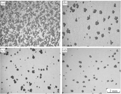
using a laser microscope. There was less evolution of hydrogen bubbles due to corrosion reactions1) at the early stage of the immersion test. The bubbles began to evolve continuously after an incubation period, then the fluoride layers were broken due to the bubble formation reactions. Specimens after immersion for 7.2 ks are shown in Fig. 1. These specimens were directly treated with fluoride, at 693 K for 0.6, 1.8, 7.2 and 10.8 ks, (a), (b), (c) and (d), respectively without the deposited magnesium layer. Dark contrasts indicate the corroded regions, which were significantly decreased when the duration of fluoride treatment was increased from 0.6 to 1.8 ks, then gradually decreased with the duration of fluoride treatment.
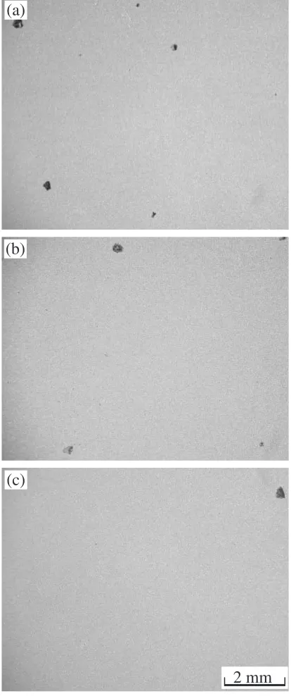
Fluoride treatment with the same conditions as those for Fig. 1(d), 693 K for 10.8 ks, was applied to the specimens with magnesium deposited layers. The results of the immersion tests with these specimens in the same acidic solution for 7.2 ks are shown in Fig. 2. The deposited layers were formed at 873, 923 and 973 K for 1.8 ks, (a), (b) and (c), respectively. Comparison with Fig. 1(d) shows that the corroded regions were obviously decreased by the deposited magnesium layer.
Results of the salt spray tests using a 5% NaCl solution for 259 ks are shown in Fig. 3. A raw specimen without any treatment (a) was severely damaged by corrosion. The conditions of the fluoride treatment for the specimens in (b) to (f) were the same, 693 K for 10.8 ks, while the specimens in (b) were treated directly with fluoride without the
deposited magnesium layer, and the specimens in (c) to (f) were fluoride-treated on the deposited magnesium layers formed at 823, 873, 923 and 973 K for 1.8 ks, respectively. Exfoliations of the fluoride layer are observed in the regions indicated by the arrows. Differences in the corrosion resistance of the fluoride treated specimens with and without the deposited magnesium layer is not as obvious the immersion tests in the acidic solution (Figs. 1 and 2).
The appearance of the cross-cut specimens after salt spray tests for 259 ks are shown in Fig. 4. The fluoride treatment duration for specimens (b) to (f) was prolonged to 173 ks in order to form thicker fluoride layers, because the cross-cut specimens were expected to suffer from severe corrosion. Other conditions were the same as those for the specimens shown in Fig. 3(a) to (f), respectively. The specimen fluoride-treated on the deposited magnesium layer formed at 873 K for 1.8 ks (d) showed the best corrosion resistance: few scratches are observed except in the circumferential areas. Conversely, the scratches seem predominantly corrod-ed in the specimen fluoride-treatcorrod-ed without the depositcorrod-ed magnesium layer (b). The dark contrast in (b) to (f) is not due to exfoliation of the fluoride layers but to the brown color of the surface. Energy dispersive X-ray analyses showed that Fe was contained in the surface fluoride layer. The browning would be due to contamination from the mild steel crucible used for the fluoride-treatments.
It was reported in the previous paper,5,6)that the fluoride layer was composed of two phases, NaMgF3 and MgF2,
(a)
(b)
(c)
(d)
2 mm
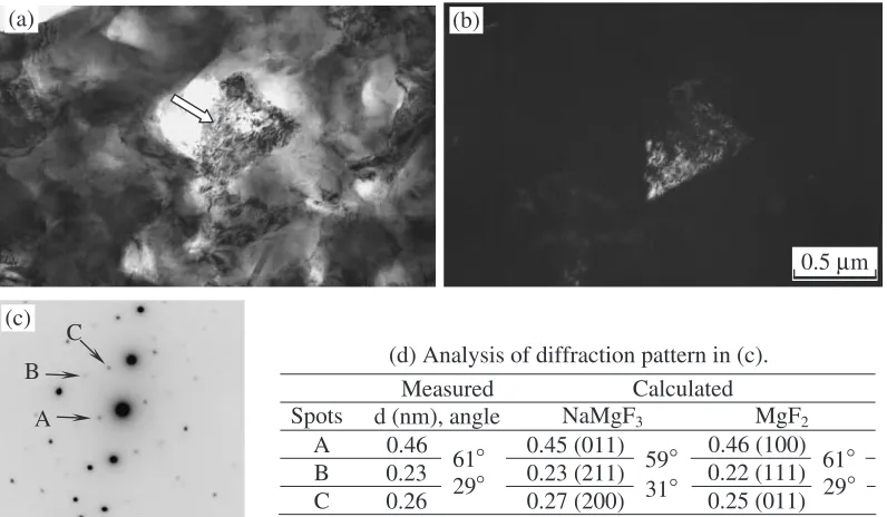
[image:2.595.89.507.71.394.2]based on synchrotron radiation (SR) diffraction measure-ments. However, the microstructures of the layer were not clarified, whether those phases are mixed or layered. Figure 5 shows the extracted fluoride layer directly formed at 693 K for 10.8 ks on the specimen without the deposited magnesium layer. The layer is composed of fine grains about 0.5mmin diameter. Bright contrasts are not due to holes in the specimen but rather to diffraction contrast and to the thickness, which was confirmed by tilting experiments. Defects such as cracks or voids were not observed. A selected area diffraction pattern was taken at the grain indicated by the arrow in Fig. 6(a), and is shown in (c). The
However, the values for MgF2 are close to the measured values.
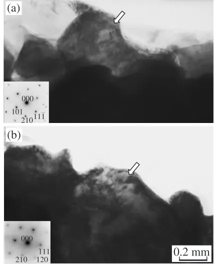
Microstructures in the fluoride layer formed on the deposited magnesium layer are shown in Fig. 7. Conditions for the fluoride-treatment are the same as for the specimen shown in Fig. 5. Magnesium deposition was carried out with the evaporation temperature of 823 K for 1.8 ks. There are no significant differences in microstructures of the fluoride layers formed with or without the deposited magnesium layer. Both of them are composed of fine grains, and did not contain cracks or voids. One of the grains with bright contrast is shown in Fig. 8. Image (a) seems to be a typical dark field image, but is a bright field image. The diffraction pattern taken at the grain is shown in (c) which is indexed as an MgF2 phase. The lattice spacings of indexed spots A, B and C in (c) are 0.33, 0.25 and 0.25 nm, respectively. Those values are close to 0.34, 0.26 and 0.27 nm for the (111), (0112) and (11221) planes in the NaMgF3 phase, respectively. However, the mirror planes indicated in (c) were not explained based on these planes. Diffraction patterns in Figs. 6 and 8 were taken at relatively thin grains with bright contrasts. Figure 9 shows the results of diffraction analyses on relatively thick grains with dark contrast. The diffraction patterns in (a) and (b) were taken at the grains indicated by the arrows. Both patterns can be indexed as the MgF2phase.
4. Discussion
Cross-sectional observations on the fluoride-treated speci-mens show that the fluoride layers with thickness of about 105) and 15mm4) were formed at 673 K for 22 ks5) and at 723 K for 86.4 ks,4)respectively. In the present study, 693 K for 10.8 ks, the formation of fluoride layers with thicknesses of about 2 to 3mmwas observed. It should be mentioned that the foil specimens with such thicknesses can not be observed by TEM under an accelerating voltage of 200 kV. In Figs. 5 and 7, microstructures of the layers were observable and only the MgF2phase was identified, while the NaMgF3and MgF2 phases were detected by SR diffraction measurements.5,6) The fluoride layer was composed of NaMgF3 and MgF2 layers, and the NaMgF3 layer was dissolved in the HCl: CH3OH¼1 : 2 solution, leaving the MgF2 layer during the extraction procedure. The corrosion resistance in the acidic solution of the NaMgF3 layer is inferior to that of the MgF2 layer.
The molar fraction of magnesium in the MgF2 phase is higher than that in the NaMgF3phase, which implies that the MgF2 layer is formed on the magnesium substrate and the NaMgF3layer is formed on the MgF2layer. In the case of the fluoride treatment on the deposited magnesium layer, the
(b)
2 mm
(c)
[image:3.595.65.272.75.569.2]substrate was covered with the three layers of pure magnesium, MgF2 and NaMgF3, from the substrate to the surface.
The MgF2layer is formed by chemical reactions between magnesium and fluorine in the molten NaBF4, so it can not be formed on inclusions which do not include magnesium. While deposition of magnesium is capable of covering such inclusions to form homogeneous microstructures, in metal-lographic and electrochemical terms, the homogeneous deposited magnesium layer leads to formation of a homoge-neous MgF2 layer which accounts for the difference in corrosion resistance of the specimens fluoride-treated with or without the deposited magnesium layer in the acidic solution (Fig. 2, and Fig. 1(d)).
For the salt solution, the NaMgF3layer showed a superior corrosion resistance as shown in Fig. 3. Poor corrosion resistance in the specimen with the deposited magnesium layer formed at the higher temperature evaporation source (Fig. 3(f)) is considered to be due to coarsening of magne-sium grains7)and roughening of the surface of the deposited magnesium layer.
Scratching the surface to prepare the cross-cut specimens
would result in grooves deeper than the thickness of the magnesium layers. Therefore, the substrate, AZ31B alloy, and pure magnesium are suffered from a salt spray in the case of cross-cut testing. Pure magnesium shows superior corro-sion resistance,4) because the corrosion proceeds with maintaining smooth corroded surfaces.9) Moreover, high purity magnesium is less noble than low impurity magne-sium;3)therefore, the deposited magnesium layer serves to protect the substrate magnesium alloy from corrosion. The difference in appearance of the specimens shown in Fig. 4 is due to these corrosion properties of the deposited magne-sium.
5. Summary
Two techniques, deposition of pure magnesium on the magnesium alloy, and fluoride treatment in which the magnesium alloy is dipped into molten NaBF4 have been combined to improve the corrosion resistance of magnesium alloy. The fluoride-treated specimens with the deposited magnesium interlayer showed superior corrosion resistance in an immersion test using a 0.02N HCl solution, and in a salt
(a)
(e)
(b)
(c)
(d)
5 mm
(f)
[image:4.595.135.462.69.457.2](c)
(d)
(e)
10 mm
(f)
Fig. 4 Results of salt spray test using a 5% NaCl solution for 259 ks on the cross-cut specimens. (a) Raw specimen without deposition coating or fluoride treatment. (b) to (f) Fluoride treatment at 693 K for 173 ks: without deposition coating (b), and on deposited magnesium layers formed at 823, 873, 923 and 973 K for 1.8 ks, (c), (d), (e) and (f), respectively.
A B
C (c)
(a) (b)
0.5 µm
(d) Analysis of diffraction pattern in (c). Measured
Spots A B C
61° 29°
61° 29° 59°
31° Calculated
d (nm), angle NaMgF3 MgF2
0.46 0.45 (011) 0.46 (100)
0.23 0.26
0.23 (211) 0.27 (200)
0.22 (111) 0.25 (011)
Fig. 6 Phase identification by TEM observation. Bright field image (a), dark field image (b) taken with the spot A shown in (c), and diffraction pattern analysis (d).
0.5 µ m
Fig. 5 Extracted fluoride layer formed at 693 K for 10.8 ks on the specimen without the deposited magnesium layer.
0.5 mµ
[image:5.595.48.290.70.434.2] [image:5.595.305.549.73.231.2] [image:5.595.306.548.290.449.2] [image:5.595.100.498.522.754.2]spray test using a 5% NaCl solution. Salt spray tests on the cross-cut specimens showed that the deposited magnesium interlayer improves the corrosion resistance at scratches.
Microstructural analyses by TEM observations revealed
that the fluoride layer was composed of two layers, MgF2and NaMgF3. The fact that the MgF2 layer remained after extraction procedures using an acidic solution shows the high corrosion resistance of this layer.
REFERENCES
1) A. Yamamoto, A. Watanabe, K. Sugahara, S. Fukumoto and H. Tsubakino: Mater. Trans.42(2001) 1243–1248.
2) H. Tsubakino, A. Yamamoto, S. Fukumoto, A. Watanabe, K. Sugahara and H. Inoue: Mater. Trans.44(2003) 504–510.
3) A. Yamamoto, A. Watanabe, K. Sugahara, H. Tsubakino and S. Fukumoto: Scripta Mater.44(2001) 1039–1042.
4) A. Yamamoto, T. Ohse and H. Tsubakino: Mater. Sci. Forum475–479 (2005) 505–508.
5) A. Yamamoto, H. Inaoka and H. Tsubakino: JJILM57(2007) 57–61. 6) T. Terawaki, A. Yamamoto and H. Tsubakino: JJILM57(2007) 269–
273.
7) R. Tamai, A. Yamamoto and H. Tsubakino: JJILM56(2006) 538–542. 8) M. Jotoku, A. Yamamoto and H. Tsubakino: JJILM56(2006) 711–715.
(a)
(b)
0.2 m
µ
m
m
110
MgF2011
MgF2100
MgF2(c)
A B
C
Fig. 8 Phase identification by TEM observation. (a) Bright field image, (b) dark field image taken with the 110 spot shown in (c), and (c) diffraction pattern superimposed with indices and mirror planes.
(a)
101 210111 000
0.2 mm
(b)
210 120 000
111
[image:6.595.59.279.72.501.2] [image:6.595.318.532.73.337.2]