BUILDING COMPLEX SYSTEMS BASED ON
SIMPLE MOLECULAR ARCHITECTURES
Craig Collumbine Robertson
A Thesis Submitted for the Degree of PhD
at the
University of St Andrews
2011
Full metadata for this item is available in
St Andrews Research Repository
at:
http://research-repository.st-andrews.ac.uk/
Please use this identifier to cite or link to this item:
http://hdl.handle.net/10023/2573
Building Complex Systems Based on
Simple Molecular Architectures
By
Craig Collumbine Robertson
A Thesis Presented for the Degree of
Doctor of Philosophy
in the
School of Chemistry
University of St Andrews
1. Candidateʼs declarations:
I, Craig Collumbine Robertson, hereby certify that this thesis, which is approximately 85,000 words in length, has been written by me, that it is the record of work carried out by me and that it has not been submitted in any previous application for a higher degree.
I was admitted as a research student in September 2006 and as a candidate for the degree of Ph.D. in September 2007; the higher study for which this is a record was carried out in the University of St Andrews between 2006 and 2010.
2. Supervisorʼs declaration:
I hereby certify that the candidate has fulfilled the conditions of the Resolution and Regulations appropriate for the degree of Ph.D. in the University of St Andrews and that the candidate is qualified to submit this thesis in application for that degree.
Date . . . signature of supervisor . . . .
3.Permission for electronic publication: (to be signed by both candidate and supervisor)
In submitting this thesis to the University of St Andrews I understand that I am giving permission for it to be made available for use in accordance with the regulations of the University Library for the time being in force, subject to any copyright vested in the work not being affected thereby. I also understand that the title and the abstract will be published, and that a copy of the work may be made and supplied to any bona fide library or research worker, that my thesis will be electronically accessible for personal or research use unless exempt by award of an embargo as requested below, and that the library has the right to migrate my thesis into new electronic forms as required to ensure continued access to the thesis. I have obtained any third-party copyright permissions that may be required in order to allow such access and migration, or have requested the appropriate embargo below.
The following is an agreed request by candidate and supervisor regarding the electronic publication of this thesis:
(iii) Embargo on both [all] of printed copy and electronic copy for the same fixed period of 1 year (maximum five) on the following ground(s):
Publication would preclude future publication;
Table of Contents...
Abstract...
Acknowledgements...
Abbreviations...
Chapter One - Introduction...
1.1 ! Introduction
1.2 ! Non–Covalent Molecular Recognition 1.2.1!Hydrogen Bonding Molecular Recognition 1.2.2 !Secondary Interactions and the Jørgensen Model 1.2.3 !Two Hydrogen Bond Motifs
1.2.4 !Three Hydrogen Bond Motifs 1.2.5 !Four Hydrogen Bond Motifs 1.3 ! Enzyme Catalysis
1.3.1 !Effective Molarity
1.3.2 !Intramolecular Reaction Rate Acceleration 1.4 ! Templates
1.4.1 !Template Directed Synthesis 1.4.2 !Interweaving Template 1.4.3 !Linear Templates
1.5 ! Minimal Model of Self–Replication 1.5.1 !Self–Replication and the Origins of Life 1.5.2 !Self–Replicating Systems Based on DNA 1.5.3 !Self–Replicating Systems Based on Polypeptides 1.5.4 !Self–Replicating Systems Based on RNA 1.5.5 !Synthetic Minimal Replicators
1.6 ! Systems Chemistry
1.6.1!Multiple Replicator Systems
1.6.2!Combining Replication Strategies With Dynamic Chemistry 1.7! Crystallisation as Method of Selectivity From a Dynamic Library 1.7.1!Mechanosensitive Self–Replication
1.8 ! Extended Systems and Molecular Logic 1.8.1! DNA Logic
1.8.2 !Extended Systems and Molecular Logic with Self–Replicators
Chapter Two - Directing Systems of Multiple Replicators...
2.1 ! Complex Systems
2.1.1 !Computational Network Experiment
v–ix
xi
xiii–xv
xvii-xviii
1-95
1 2 3 6 7 8 8 12 15 15 20 22 23 24 30 32 36 40 44 46 63 64 70 82 84 87 89 92
97-188
2.1.2 ! Two Replicators In One System – OR Gate 2.2 ! Aims of Project
2.2.1 ! Synthesis of para–Nitrone 52
2.2.2 ! Synthesis of meta–Nitone 58
2.2.3 ! Synthesis of Maleimides 29 and 60
2.3! Characterisation of Self–Replicating Systems
2.3.1 ! Analysis of the reaction of Maleimide 29 with meta–Nitrone 58
2.3.2 ! Analysis of the reaction of Maleimide 29 with para–Nitrone 52
2.3.3 ! Isolated Replicator Conclusions 2.3.4 ! Cross–Catalysis Investigations 2.4 ! Competitive Two Replicator System 2.4.1! Template Instruction of System
2.5 ! Coupling the Two Replicator System to a Dynamic Process 2.5.1 ! Template Direction of a Dynamic Reagent Pool
2.6 ! Summary of two replicator systems 2.7 ! Change of Maleimide
2.7.1 ! Analysis of the reaction of maleimide 72 with p–nitrone 52
2.7.2 ! Analysis of the reaction of maleimide 72 with m–nitrone 68
2.7.3 ! Investigation for Cross–Catalysis 2.8 ! Two Replicator Kinetic System
2.8.1 ! Template Instruction of Two Replicator System
2.9 ! Coupling Two Replicator System to a Dynamic Process 2.9.1 ! Template Direction of Dynamic Two Replicator System 2.10 ! Direction of a Mixture of Simple Components
2.11 ! Extended System of Dynamic Reagents 2.12! Summary of Two Replicator Systems
2.13 ! Design and Characterisation of a Third Self–Replicating System 2.13.1! Synthesis of Biphenyl Nitrone 82
2.13.2! Synthesis of Long Nitrone 83
2.13.3! Analysis of the Reaction of l–Nitrone 83 with Maleimide 72
2.14! Expanding the Replicator Network - Three Replicator System 2.14.1 ! Template Direction of Three Replicator System
2.15! Coupling Three Replicator System to a Dynamic Pool of Reagents
2.15.1 ! Template Direction of Three Replicator System with Dynamic Reagent Pool 2.16 ! Three Replicator System From Simple Components
2.16.1! Template Direction of Simple Components 2.17 ! Overall Conclusions
Chapter Three - An Orthogonal Reciprocal Replicating System...
3..1 !Replication and the Origin of Life 3.1.1 !Reciprocal Replication
3.1.2 !Synthetic Reciprocal Template Effects
3.2 ! Design of an Orthogonal Reciprocal Replicator 3.2.1!Molecular Modelling
3.2.2 !Synthesis of Nitrones 91 and 92
3.2.3 !Synthesis of Maleimides 34 and 72
3.2.4 !Synthesis of Aniline 88
3.2.5 !Synthesis of Aldehydes 89 and 90
3.2.6 !Synthesis of Imines 97 and 98
3.2.7 !Amine Synthesis
3.3 ! Template Effects in a Reciprocal System
3.3.1 !Phenylacetic Nitrone 92 and Phenylacetic Maleimide 34
3.3.2!Carboxy Nitrone 91 and Phenylacetic Maleimide 34
3.3.3 !Phenylacetic Nitrone 92 and Carboxy Maleimide 72 3.3.4 !Carboxy Nitrone 91 and Carboxy Maleimide 72
3.4 ! Investigation of the Origin of Cis Selectivity
3.5 ! Acceleration of the Reaction of m–Nitrone 91 with m–Maleimide 72 by an Imine Template 3.5.1 !Reciprocal Template Effect
3.6 ! Four Component Reciprocal Replicator 3.6.1 !Template Instruction of Reciprocal System 3.7 ! Evolution of Reciprocal System
3.7.1 !Synthesis of Nitrone 113
3.7.2 !Reactivity of Nitrone 113 towards Maleimide 72
3.8 ! Reciprocal Replicating System
3.8.1 !Template Instruction of Reciprocal Replicating System 3.9! Environmental Dependence of Replication Mechanism 3.10 !Conclusions
Chapter Four - Rational Design of a Bifunctional Replicator...
4.1 ! Introduction
4.2! Combining [A•B] Complex Channel and Autocatalysis. A Fresh Perspective 4.3 ! Design of the Bifunctional System
4.4 ! Designing an [A•B] Complex Pathway 4.4.1!Opening Recognition Sites on AB Template 4.4.2 !Synthesis of Nitrone 121
4.4.3 !Synthesis of Nitrone 52
189–240
189 191 194 198 201 202 203 203 204 204 205 205 207 208 209 210 212 216 223 225 229 230 231 232 233 236 237 239
241–295
4.4.4 ! Kinetic Behaviour of [A•B] System
4.5 ! Kinetic Behaviour of the Self–Replicating System
4.6 ! Synthesis of Bifunctional Nitrone 120
4.6.1 ! Kinetic Analysis of the Reaction of Nitrone 120 with Maleimide 34
4.7 ! Relative Efficiencies of the Three Recognition Mediated Systems
4.8 ! ! Cross–Catalytic Doping Reactions
4.9 ! ! Increasing the Solubility of Reagents in Non–Polar Solvents
4.10 ! ! Determination of Association Constant
4.11 ! ! Kinetic behaviour of [A•B] system
4.12 ! ! Kinetic behaviour of self–replicating system
4.13 ! ! Kinetic Behaviour of the Bifunctional System
4.13.1 ! Further Investigations and Characterisation of Origins of Bifunctional Behaviour
4.14 ! ! Comparison of Efficiencies of Functionalities
4.15! ! Cross–Catalytic doping Reactions
4.16 ! ! Conclusions From Bifunctional System
4.17 ! ! Future Work: Adding Bifunctionality to Existing Replicators.
4.18 ! ! Overall conclusions
Chapter Five - Autocatalytic Supramolecular Polymer Synthesis...
5.1 ! ! Nanoscale Construction – Engineering with Replication
5.1.1 ! ! Conventional Covalent Polymers
5.2 ! ! Supramolecular Polymers
5.2.1 ! ! Applying Self–Replication to Supramolecular Polymer Synthesis
5.3 ! ! First Generation Monomer Design
5.4 ! ! Second Generation Monomer Design
5.5 ! ! Third Generation Monomer Design
5.5.1 ! Model Compound for Analysis: mono Nitrone
5.5.2 ! Kinetic Analysis of the Reaction of mono Nitrone 155 with Maleimide 34
5.5.3 ! Kinetic Analysis of Bisnitrone 152 with Maleimide 34
5.5.4 ! Cross Doping Reactions
5.5.5 ! ! Conclusions From Kinetic Analysis
5.6 ! ! Properties of Bistemplate – Evidence for Supramolecular Polymerisation
5.7 ! ! Concentration Dependence on Polymer Length
5.7.1 ! ! Diffusion Ordered Spectroscopy
5.7.2 ! ! Results of DOSY Experiments
5.7.3 ! ! Extension of Linker
5.8 ! ! Physical Properties of Supramolecular Polymer
5.9 ! ! Conclusions
254
258
261
261
267
269
272
275
277
279
282
285
287
288
290
291
294
297–340
297
300
301
303
305
308
309
311
312
315
321
323
323
327
329
332
334
337
Chapter Six – Overall Conclusions...
6.1 ! Overall Conclusions
Chapter Seven – General Experimental and Characterisation of...
! !! Compounds
7.1 ! General Experimental Procedures
7.2 ! Preparation and Analysis of Two or Three Replicator Experiments in Chapter 2 7.3 ! Preparation and Analysis of Two or Three Replicators Coupled to a Dynamic
! Process Experiments in Chapter 2
7.4 ! Preparation and Analysis of Two or Three Replicators from Simple Components
! Experiments in Chapter 2
7.5 ! Preparation and Kinetic Monitoring of Experiments by 1H NMR spectroscopy and ! Deconvolution of Data used in Chapter 2, 3, 4 and 5.
7.6 ! Preparation and Kinetic Monitoring of Experiments by 19F NMR
! spectroscopy and Deconvolution of Data used in Chapters 2, 3, 4 and 5. 7.7! Kinetic Simulation and FItting
7.8 ! Characterisation of Compounds
Chapter Eight – References...
8.1 ! References
Chapter Nine – Appendix...
A1. ! Typical SimFit input file for a Bimolecular control reaction with explanation of commands A2. ! Typical SimFit input file for a Self–Replicating reaction
A3. ! Four Product System Simulation SimFit Input File (All Rate Equal) A4. ! Four Product System Simulation SimFit Input File (AB Rate Enhanced) A5. ! Publications
341–343
341
345–410
345 348 349
350
351
354
354 355
411–418
411
A1–A5
Abstract
Over the past twenty years molecules capable of templating their own synthesis, so
called self–replicating molecules have gained prominence in the literature. We show
herein that mixing the reagents for replicating molecules can produce a network of
self–replicators which coexist and that the networks can be instructed by the addition
of preformed template upon initiation of the reaction.
Whist self–replicating molecules offer the simplest form of replication, nature has
evolved to utilise not minimal self–replication but reciprocal replication where one
strand templates the formation of not an identical copy of itself but a reciprocal
strand. Efforts thus far at producing a synthetic reciprocal replicating system are
discussed and an alternative strategy to address the problems encountered is
proposed and successfully implemented.
The kinetic behaviour of a self–replicating reaction bears two distinctive time periods.
Upon initiation, the reaction proceeds slowly as no template exists to catalyse the
reaction. Upon production of the template, the reaction proceeds more rapidly via
template direction. During this slow reaction period, the system is prone to mistakes
as the reaction is slow and unselective. The creation of an [A•B] binary complex through non–covalent recognition of reagents allows for the reaction to proceed at an
accelerated rate upon initiation however products of such a reaction are usually
catalytically inert and do not promote further template directed reaction. A strategy to
combine the desired behaviour of an [A•B] binary complex with the further template directed autocatalytic self–replicating reaction is described and implemented.
Supramolecular polymers consist of repeating monomers which are held together by
non–covalent interactions. The strong association of a self–replicating template dimer
is comparable to that of supramolecular polymers reported thus far in the literature
which are produced by cumbersome standard linear synthetic procedures. Herein the
application of self–replication to the field of supramolecular polymer synthesis is
discussed. As the autocatalytic reaction to produce the template monomers occurs
under the same conditions as required to allow polymerisation to proceed, the
polymer is able to spontaneously form in situ by self–replicating supramolecular
Acknowledgements
I would firstly like to thank my supervisor Prof. Douglas Philp for accepting me into his research group, letting me loose in his lab and for all of his enthusiasm, encouragement and guidance during my time in St. Andrews which has made this thesis not only possible but enjoyable to prepare.
I would also like to thank all the members of the Philp research group, past and present, which whom I have enjoyed gazing out of the lab window over the wonderful view of The Old Course, West Sands and the Grampian Mountains. The very knowledgeable postdocs Dr Simon Turega, who helped get me started in the lab and introduced me to Wagamama noodles, and Dr Vicente del Amo who make lab work look easy and whose dedication to Real Madrid and waterpolo could not be faltered! (Dr) Jürgen Huck, güten morgen to you, thank you for too much to mention. You have been a great friend in and out of the lab. It has been a pleasure and a privilege to work with you. Best of luck for your golf in the future, I shall miss you dearly. (Dr) Izzaty Hussan, it has been a pleasure to have met and worked with you. I wish you all the best of luck for your future when you return home to Malaysia. Dr Ilaria Bottero for shining some light (excuse the chemistry pun!) into the lab! Thank you Dr Jan Sadownik for always being fun to work with and Dr Annick Viddone for showing me how to do everything properly! I must also thank the project students who helped make the lab a wonderful place to work for so many years.
Thank you Dr Neil Keddie, not only for your help and knowledge in the lab, but for being a great friend, dog sitter and chilli chef! I enjoyed many walks on many beaches with yourself, Katy and Sanna. I do dearly miss them now we have moved although I very much look forwards to joining you again sometime soon with your new addition Joshua Jack Keddie. Many congratulations.
Over the many years I have lived in St. Andrews, I have had the good fortune to make many good friends as an undergraduate, as part of the Ents crew in the union, and as a postgraduate. Dr Craig Campbell and Neil McDowell are two very special friends who did a wonderful job suffering my friendship and a wonderful job as best men at my wedding. I am eternally indebted to them both.
My thanks must also go to my wonderful wife Jennifer, who is actually asleep on my shoulder as I typed this, for being very tolerant and helpful during the lost weekends and evenings she has endured during the preparation of this thesis. I promise to make them up to you. Thank you for all your love and support through this process and for the all the time since we met. You are my best friend and a wonderful wife and I look forwards to the rest of our lives together. Thank you for introducing me to your lovely yellow lab Saffron who definitely made me a dog lover. Saffy sadly has now passed away but she is not forgotten and we are now lovingly tormented by one of her relatives, a black lab called Bella whom I enjoy exploring with just as much.
Abbreviations
A! Adenosine
A! Hydrogen Bond Acceptor
C! Cytosine
CBPQT! Cyclobis(paraquat–p–phenylene)
D ! Hydrogen Bond Donar
D ! Diffusion Coefficient
DAN! 2,7–Diamino[1,8]naphthyridine DCC! Dicyclohexyldiimide
DCC! Dynamic Covalent Chemistry DCL! Dynamic Combinatorial Library DBU! 1,8-Diazabicycloundec-7-ene DFT! Density Field Theory
DMAP! p–Dimethylaminopyridine DMSO! Dimethylsulfoxide
DNA! Deoxyribonucleic Acid
DNP! Dioxynaphthalene
DOSY! Diffusion Ordered Spectroscopy DP! Degree of Polymerisation
E–coli! Escherichia coli
EDC! 1-Ethyl-3-(3-dimethylaminopropyl)carbodiimide EDTA! Ethylenediaminetetraacetic acid
ee! Enatiomeric excess
EM! Effective Molarity
EtOAc ! Ethyl Acetate
G! Guanidine!
HMDS! Hexamethyldisilazane HMTA! Hexamethylenetetraamine
HPLC! High Performance Liquid Chromatography HRMS! High Resolution Mass Spectrometry
Ka! Association Constant
Kd! Dissociation Constant
MALDI! Matrix–Assisted Laser Desorption/Ionisation
Abbreviations
MS! Mass Spectrometry MTM ! Thiomethyl
NAC! Near Attack Conformation NMR! Nuclear Magnetic Resonance PCR! Polymerase Chain Reaction Pd/C! Palladium on Activated Carbon
p–TSA! p–Toluenesulfonic acid
Rh/C! Rhodium on Activated Carbon RNA! Ribonucleic Acid
RT! Room Temperature (25 ˚C)
T! Thymine
TFA! Trifluoroacetic Acid THF! Tetrahydrofuran
TLC! Thin Layer Chromatography TOF! Time of flight
TTF! Tetrathiofulvalene
U! Uracil!
UG! Urea guanine
1
Introduction
1.1 Preamble
The modern day synthesis of complex organic molecules for the purposes of
biomedical research, such as in the drug discovery industry, is centred around the
exploitation of covalent transformations brought about by centuries of systematic
research. Nowadays, complex compounds such as those isolated from nature, for
example taxol, can be produced and modified by a wholly synthetic method.1,2 Whilst
the purpose for creating these compounds is biological in nature, their synthesis does
not exploit the wealth of knowledge accumulated by biological systems which have
had millions of years to evolve into complex and highly efficient machines for
catalysis and information storage.
One field of chemistry that is taking inspiration from processes observed in nature is
the field of supramolecular chemistry which is described3-6 as chemistry beyond the
molecule. Much like nature uses non–covalent interactions to organise the structure
of proteins and the storage of genetic information in DNA, supramolecular chemistry
is concerned with the assembly of structures, often from discrete units, associated by
non–covalent interactions. The structures produced vary widely in nature with
mechanically interlocked molecules,7 molecular sensors8,9 and artificial enzymes10-13
perhaps the most well documented examples. The non-covalent interactions used
vary in strength but are usually transient in nature which means they can be
conveniently controlled by outside interference or by internal processes.
The study of non–covalent interactions is crucial to the understanding of self–
organisation responsible for all cellular processes and life itself. The lessons learned
from this understanding also has lead to the development of many novel materials
1.2 Non–CovalentMolecular Recognition
For over a century, organic chemists have investigated covalent chemical reactions
in such a way that a wealth of synthetic methodologies are available for countless
organic transformations. The covalent bonds formed by such reactions are high in
energy with typical carbon–carbon bond strengths of ~340 kJmol–1 produced.14,15
Table 1.1: ! Typical values of covalent and non–covalent interactions between molecules/atoms. Compiled
! from references 14 and 15.
Interaction Bond Strength
(kJmol–1)
Covalent C–C bond Typically 340
Hydrogen Bonding Most commonly 1–20 (up to 160) Salt Bridge 1–12
ᴨ–ᴨ < 4
Molecules are also able to transiently interact with each other by comparatively low
energy, non–covalent interactions such as hydrogen bonds,16-23 Van der Waals
forces24,25 or hydrophobic forces.22,26 Molecules recognise each other on account of
the favourable interactions formed from associating with each other as opposed to
the bulk solution. The importance of non–covalent interactions for life to exist cannot
be over emphasised. These interactions are critical in countless biological processes
for example hydrogen bonding between base pairs is utilised to store and transfer
genetic information in DNA and give rise to the iconic double helix structure.
Enzymes responsible for the regulation of cellular activities use hydrogen bonding,
ion pairing and ᴨ– ᴨ forces in concert to exert their exquisite substrate specificity.
The importance of molecular recognition began to intrigue scientists after the
accidental discovery of crown ethers (Figure 1.1) by Pedersen27,28 which lead to
subsequent work on synthetic receptors for charged cations and neutral molecules
by Cram29 and Lehn.30 The three were later awarded a Nobel prize for their work
O O O O
12–Crown–4 15–Crown–5 18–Crown–6
O O
O O
O O
O O
O O
O
Li Na K
Figure 1.1: ! Variety of crown ethers of different ring sizes. The identity of the cation which is bound is
! determined by the cavity size of the ring.
A complete discussion of the wide variety of molecular recognition is beyond the
scope of this thesis and indeed many journal reviews. As such only the molecular
recognition which arises from hydrogen bonding, which is the basis for the work to be
described, will be discussed briefly.
1.2.1 Hydrogen Bonding Molecular Recognition
The directionality and relative strength of hydrogen bonds make them the most useful
of all non–covalent recognition motifs in self–assembly.15 A hydrogen bond is formed
between molecules containing a polar X–H bond and the non–bonding electron pairs
on atom Y. As demonstrated in Figure 1.2, the X–H bond is referred to as the
hydrogen bond donor (D) and Y the hydrogen bond acceptor (A) with the hydrogen
bond itself denoted by dashed lines. The relative strength of hydrogen bonds is
determined by the magnitude of the dipole moment between D and H. Thus with
atoms of high electronegativity such as oxygen, nitrogen and fluorine, larger dipoles
and hence stronger hydrogen bonds are produced.
D H
A
δ δ δ
Figure 1.2:! Schematic of a hydrogen bond between a hydrogen atom attached to an electronegative donor
! atom D and the non bonding electron pair of an acceptor atom A.
There are a number of functionalities that by the definition given above are able to
dimerise through a single hydrogen bond for example phenols and amines. These
single hydrogen bonded structures are short lived and consequently of little use for
host–guest chemistry. When two or more hydrogen bonds are employed as
molecular recognition, straightforwardly thinking the complex should form with a
strength equal to the sum of the two hydrogen bonds. In reality, the complex will form
with a strength stronger, or weaker than the two hydrogen bonds combined in a
A1 A2
A1 A2 A1 A2 A1 A2
A1 A2
A1 A2
D1 D2
D2 D1
D2 D1 D2 D1 D2 D1
D1 D2
ΔG˚ = ΔG1 + ΔG2 – ΔGs
ΔG1 ΔG2
D (i)
(ii)
A A
A A
D
D D
ΔG˚ = –RTlnKA
[A•D] [A•D] +
KA
Scheme 1.1: !(i) Reversible association of hydrogen bond donors with two unconnected acceptors. Each
! association has an unique free energy of association ΔG°. (ii) Reversible association of two
! connected hydrogen bond donors with two connected acceptors. Each association once again has
! an unique energy of association ΔGn with the total energy of binding the two acceptors determined
! by summing the free energy of each binding interaction and subtracting the connection free energy
! ΔGs. Figure adapted from reference 31.
If we consider a reversible association of a hydrogen bond donor with a
complementary acceptor (Scheme 1.1 (i)), the binding has a free energy of ΔG°.
Chelate cooperativity arises when two or more donors and acceptors are connected
together (Scheme 1.1 (ii)) and the the total energy of binding now includes a term to
describe the connection free energy, ΔGs.
(1)
!
G˚
=
!
G
1+
!
G
2–
!
G
s(2)
!
G
s=
!
G
1+
!
G
2–
!
G˚
Equation 1.1: ! (1) Equation of free energy from binding the guest to the host with two hydrogen bonds. Each of
! the two bonds has a unique strength represent for D1–A1 by ΔG1 and for D2–A2 by ΔG2. ΔGs
! denotes the connection free energy. (2) Equation rearranged to determine ΔGs.
In a positively cooperative system, after the association of the first donor and
acceptor, the connection orientates the second acceptor in a spacial arrangement
be greater then the sum of the two isolated associations meaning ΔGs is +ve,
Equation 1.1 (1). This value represents that after associating the first hydrogen bond,
it is easier to associate the second hydrogen bond in comparison to it being
unconnected to the first.
Conversely, the first association of donor with an acceptor may make the second
association unfavourable, most trivially because of poor orientation of the second
association site with respect to the donor. In this case it is less favourable for second
association to occur therefore in comparison to if it were unconnected to the first and
ΔGs would be –ve. Instead of forming the chelated macrocycle, the
thermodynamically more favourable polymer chain will form.
(1) Ka=[Host•Guest]
[Host][Guest]
(2) !GS=RT ln(K[Host•Guest] KD1A1KD2A2 )
Equation 1.2: ! (1)Equation to determine the association constant of the host–guest complex (2) Gibbs free
! energy equation to determine ΔGs.
The association constant (Ka) can be determined experimentally,14 Equation 1.2 (1),
and from these results, and the equilibrium constants of individual hydrogen bonding
interactions (which can be obtained from experimental determination with control
compounds), the connection free energy, ΔGS can be determined, Equation 1.2 (2).
It is worth noting at this point that the strength of hydrogen bonds is highly dependent
on their environment. For example, a host and guest dissolved in a non–polar solvent
such as chloroform will not experience competition for the hydrogen bonding site and
a high Ka could be observed. If that same complex were dissolved in DMSO, a highly
polar solvent, the hydrogen bond acceptors on DMSO would compete for those on
the host or guest and thus disrupt the desired association. The observed Ka in this
case will be significantly lower. Likewise increasing the temperature of a solution will
lower the Ka of a host guest complex, lowering the temperature will increase the Ka.
Therefore strictly speaking the magnitude of a hydrogen bond is useless unless
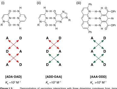
1.2.2 Secondary Interactions and the Jørgensen Model
In 1967 Rich and co workers32 produced triple hydrogen bonding dimeric complexes
and discovered that different motifs had surprisingly different association constants
which ranged from ~102 to 105 M–1 in CHCl3 at room temperature. As each structure
had three hydrogen bonds, obviously more than just the number of hydrogen bonds
were responsible for the stabilities of complexes. This observation inspired
Jørgensen and co workers to investigate and more than 20 years later they
showed33,34 that the difference is stability correspond to attractive or repulsive
secondary interactions. When there are two or more hydrogen bonds adjacent to
each other, a secondary interaction arises which can either strengthen or weaken the
primary hydrogen bond. Stabilisation arises from electrostatic interactions between
positively and negatively polarised atoms on adjacent hydrogen bonds and will
strengthen the hydrogen bond. Destabilisation arises from repulsive electrostatic
interactions between two positively or two negatively polarised atoms on adjacent
hydrogen bonds and will weaken the hydrogen bond.
A D D D A A N N N N R O N H H H N H O N R N H N N N Ph Ph N N N H H H H H Ar OPr O OPr O A D A D A D N N N H H H N H O N R O H A A A D D D [ADA•DAD] Ka ~102 M–1
[ADD•DAA] Ka ~104 M–1
[AAA•DDD] Ka >105 M–1
(i) (ii) (iii)
Figure 1.3: ! Demonstration of secondary interactions with three dimerising complexes from Jørgensen (i)
! and (ii) and Zimmerman (iii). (i) [1–methyluracil•2,6–diaminopridine](ii) [1–
! methylcytosine•9–methylguanine] and (iii) [pyrido[2,3–b][1,8]naphthyridine•1,4–
[image:25.595.75.462.402.698.2]Jørgensen used molecular dynamics calculations to demonstrate that [ADD•DAA]
complex (ii) (Figure 1.3) was 10.7 kcalmol-1 (45 kJmol–1) lower in energy than
[ADA•DAD] complex (i) (Figure 1.3). These results concurred with the experimental
data that showed complex (ii) to be more stable than complex (i). The model predicts
that the strongest complexes should be formed from [AAA•DDD] complexes which
maximise positive secondary interaction.
The next year, Murray and Zimmerman produced35 a library of triple hydrogen bond
complexes to investigate Jørgensenʼs model including a [AAA•DDD] complex (Figure
1.3 (iii)). The association constants for [ADA•DAD], [DAA•ADD] and [AAA•DDD]
complexes were found to be in the order 102 M–1, 103–104 M–1 and 105 M–1 in CHCl3
at 25 ˚C respectively, thus concurring with Jørgensenʼs model. Schneider devised an
empirical free energy relationship for the prediction of multiple hydrogen bonded
complexes in CHCl3.36 Primary hydrogen bonds were assigned a value of –8 kJmol–1
with secondary interactions given –2.9 kJmol–1 or +2.9 kJmol–1 for attractive or
repulsive interactions respectively.
1.2.3 Two Hydrogen Bond Motifs
Common organic functional groups such as carboxylic acids are able to dimerise
through two hydrogen bonds (Figure 1.4 (i)). Nature utilises a two hydrogen bond
motif as well in the adenine–thymine base pair (Figure 1.4 (ii)).
O O
H O O H
N N N N R
N H H
N N O H
R O
(i) (ii)
Figure 1.4: ! (i) Benzoic acid dimerises by two hydrogen bonds. (ii) The base pair of adenine and thymine
! associates with two hydrogen bonds.
Isolated synthetic two hydrogen bonding complexes are generally considered to be
weak. The enthaplic gain of associating two molecules is generally outweighed by
entropic loss and thus higher concentrations (>10 mM) are required to form high
concentrations of the complex. The relative stability of [AA•DD] motifs is calculated
and experimentally demonstrated23 by Zimmerman et al to be be stronger than the
however, examples of non–covalent assemblies constructed based on a pair of two
hydrogen bonding units connected together which will be discussed later in the four
hydrogen bond motif Section 1.2.5.
1.2.4 Three Hydrogen Bond Motifs
The base pair of cytosine to guanine is natures greatest example of a triple hydrogen
bonding complex (Figure 1.5 (i)). It is interesting to note that in each case, the base
pairs to do not maximise the number of positive secondary interactions to achieve the
strongest possible binding strength. Perhaps nature has evolved this way to avoid
base pairs which are too strong and thus unable to dissociate for cellular functions.
N N N
N
N N
H
H H H
H
O OEt O
OEt NO2
N N N
N
N N
H
H H H
H
N N O
N H H N
O N R
N H
N N H
H
R'
Ka ~102 M-1 K
a 2 × 10
7 M-1 K
a 3 × 10 10 M-1
(i) (ii) (iii)
Figure 1.5: ! Triple hydrogen bonding complexes. (i) natural base pair of cytosine to guanine [C•G]. (ii) Very
! strong neutral triple hydrogen bond complex produced37 by Leigh et al. (iii) Cationic triple
! hydrogen bond complex described19 by Leigh etal forms a very strong duplex.
As mentioned previously, the work of Jørgensen and Zimmerman independently
produced an array of triple hydrogen bond complexes. Zimmerman demonstrated at
that time the strongest [AAA•DDD] complex had a Ka of ~105 M–1. More recently,
Leigh etal have produced very strong neutral37 (Ka 2 ⨉ 107 M–1) (Figure 1.5 (ii)), and
cationic19 (Ka 3 ⨉ 1010 M–1) (Figure 1.5 (iii)), triple hydrogen bond complexes.
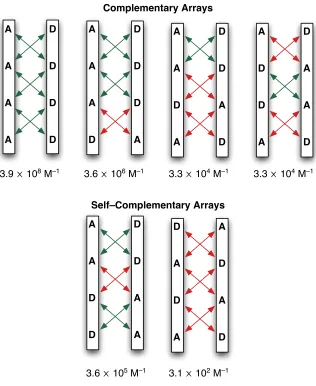
1.2.5 Four Hydrogen Bond Motifs
Apart from the obvious expected increase in strength by adding a further hydrogen
bonding interaction between host and guest, the even number of D and A atoms in a
4-hydrogen bond array means that structures which are self–complementary are able
complementary arrays and two self–complementary arrays38 (Figure 1.6). These self–
complementary structures provided the basis for work on supramolecular polymers
by Meijer etal and indeed for the design of self-replicating templates produced in our
laboratory which will discussed later.
A
A
A
A
D
D
D
D
A
A
A
D
D
D
D
A
A
A
D
A
D
D
A
D
A
D
D
A
D
A
A
D
A
A
D
D
D
D
A
A
D
A
D
A
A
D
A
D Complementary Arrays
Self–Complementary Arrays
3.9 ⨉ 108 M–1 3.6 ⨉ 106 M–1 3.3 ⨉ 104 M–1 3.3 ⨉ 104 M–1
[image:28.595.153.469.169.555.2]3.6 ⨉ 105 M–1 3.1 ⨉ 102 M–1
Figure 1.6:! All six arrangements of D and A sites in a four hydrogen bonding complex. The top four
! arrangements are complementary and thus require two different molecules. The bottom two are
! self–complementary and can be achieved by identical molecules. Secondary interactions are
! shown by red or green arrows as before. Association constants of complexes are theoretically
! determined by Schneiderʼs rule36 discussed above. Figure adapted from reference 38.
Meijer and co workers demonstrated16,17 a four hydrogen bonding array of 2–ureido–
4(1H)–pyrimidinone (UPy) derivatives. The ability of UPy derivatives to undergo
tautomerisation between two self–complementary motifs, [DADA•ADAD] and
[AADD•DDAA], complicates their analysis however strong Kas of 3.6 ⨉ 105 M–1 and
The difference in strength, as expected from Schneiderʼs model, for the
[DADA•ADAD] tautomer was attributed to the preorganisation of the hydrogen
bonding array by the formation of intramolecular hydrogen bonds and differences
from D atoms used by Schneiderʼs examples. The UPy unit has been successfully
used as a non–covalent interaction for supramolecular polymers by linking two UPy
units together. This application is discussed further in this thesis, Section 5.2.
Zimmerman etal have explored the use of four hydrogen bonding arrays to produce
a pair of strongly binding complementary templates39 and applied them into the
creation of polymer blends.40 When the arrays were capable of tautomerisation,
which altered the arrangements of A and D atoms, such as with UPy, problems were
encountered with the formation of undesired complexes. Zimmerman coined the term
fidelity41 to describe the extent to which the desired complex is formed over other
possible complexes.
Fidelity = [Desired Complexes]
[All Possible Complexes]
Equation 1.3: ! Fidelity is the mole fraction of the desired complex.
Scheme 1.2. ! UPy 4 hydrogen bond derivatives and their association constants as described by Meijer etal.
N N
O R1
N N O H
H
R2
H
N N R1
N O H O
H
N H R2
N N
O R1
N N O H
H
R2
H
N
N
O
R1
N N
O H H
R2
H
N N R1
N O H O
H
N H R2
N
N
R1
N O
H
O H
N H R2
[AADD•DDAA]
Ka = >106 M–1
[DADA•ADAD]
Zimmerman attempted to make a copolymer blend in which one hydrogen bonding
array (UPy or UG) was attached to one type of covalent polymer and the
complementary template (DAN) was attached to a second covalent polymer normally
not known to form a blend with the first. When UPy was used, no polymer blend was
seen to be formed as a result of the strong propensity for UPy to self associate rather
then associate with DAN, therefore having a low fidelity. The UG array however has
high fidelity binding for DAN and a lower propensity for self–association. When UG
was attached to the polymer instead of UPy, association of UG with DAN lead to the
formation of a polymer blend. (Figure 1.7 (ii)).
N N N
N H O Bu
H O
Bu
O
N N
N N
N O
HN H H
Bu
O OR'OR' RO
(i) (ii)
DAN
UG
Figure 1.7: ! (i) Example of a four hydrogen bond array between DAN and UG reported39 by Zimmerman
! and (ii) the implementation of the hydrogen bonding arrays into a copolymer blend.
An alternative design for a four hydrogen bonding motif as eluded to earlier is to
combine a pair of established two hydrogen bonding motifs together. This approach
was demonstrated by Wuest and co workers who linked two self–complementary 2–
pyridone units together20,21,42,43 (Figure 1.8).
N N
H O H O
N N
H O H
O
[DADA•ADAD]
Ka = 6 × 10⁴ M–1
In work which would later be applied by this group and that of von Kiedrowski et al,
Hamilton described a receptor for adipic acid which used four hydrogen bonds based
on linking a pair of two hydrogen bonding motifs44 (Figure 1.9).
O
N N
O
H H N
N
H O
O
O H
O
Figure 1.9:! Receptor for adipic acid designed by Hamilton et al operates with 4 hydrogen bonds.
The authors noted that addition of solid adipic acid to a solution of the
bisamidopyridine receptor in chloroform lead to rapid dissolution of the normally
insoluble diacid. The authors attempted to determined the strength of the association
constant for the four hydrogen bonded motif by dilution experiments monitored by 1H
NMR spectroscopy, however no change was seen within NMR spectroscopy
detectable concentrations which indicated a Ka > 105 M–1.
Whilst hydrogen bonding motifs of greater than four hydrogen bonds have been
reported45 they shall not be discussed here.
1.3 Enzyme Catalysis
Enzymes are the most revered of all catalysts and do more than merely accelerate
simple chemical reactions, they also have a high degree of selectivity with the ability
to be substrate specific and promote stereospecific reactions with efficiencies most
catalytic chemists would marvel at. All of this is also achieved in an aqueous
environment at physiological pH whereas many of the transformations they promote
require organic solvents or harsh reagents to be reproduced in a laboratory setting.
Enzymes, like traditional catalysts, do not alter the equilibrium for a reaction, nor are
they consumed by the reaction they catalyse. However enzymes are unique from
many other forms of catalysis as they are very specific for the substrates whose
reactions are catalysed. It was noted46 by Fischer as early as 1894 that enzymes are
specific catalysts and this specificity was as a result of the enzyme and substrate
possessing a specific geometry of complementary shapes which could fit exactly into
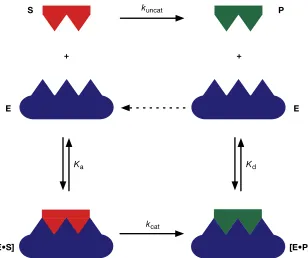
A characteristic of enzyme catalysis is that they follow Michaelis–Menten kinetics14,47
(Scheme 1.3). The reaction is initiated by association of the substrate S on to the
enzyme E, Ka, to form an enzyme substrate complex [E•S]. Covalent reaction can
then proceed at a rate, kcat, far greater than the uncatalysed process, kuncat, to
transform the substrate into the product which remains associated with the enzyme in
an enzyme product complex [E•P] until dissociation releases the product P and frees
the enzyme to undertake further catalysis. This hypothesis often referred to as the
ʻlock and keyʼ model provides an oversimplified explanation to the substrate
specificity. Whilst the equilibrium leading to the formation of the [E•S] complex
rationalises the substrate specificity of enzymes, the ʻlock and keyʼ model implies that
kuncat
kcat
+ +
S P
E E
[E•P] [E•S]
[image:32.595.157.465.86.344.2]Ka Kd
Figure 1.10: ! Cartoon representation of the enzyme E in blue with a well defined binding geometry specific
! for the complementary substrate S in red. Association of the substrate forms the enzyme
! substrate complex [E•S] which undergoes a covalent reaction to form the enzyme product
! complex [E•P] which can then dissociate to free the product P and release the enzyme to begin
! catalysis again.
Uncatalysed ! ! S !k!!uncat" P
Enzyme catalysed E + S Ka ! "!
# !! [E•S] ! "k!!cat [E•P] ! "K!d
# !! E + P
Scheme 1.3: ! Top: An uncatalysed reaction from a substrate to a product is slow proceeding at rate kuncat. ! Bottom: Enzyme catalysed reaction. Association of the substrate on to the enzyme, Ka leads to
! the formation of an enzyme substrate complex [E•S]. Reaction within the complex, kcat,
! proceeds at an increased rate in comparison to kuncat and produces the enzyme product
! complex [E•P]. Dissociation of the product from the complex, Kd, releases the product to
enzymes are rigid structures whilst in actuality enzymes are reasonably flexible
structures. In some examples,48 enzymes failed to catalyse related structures to
known substrates or a dramatically reduced catalytic ability was observed. In order to
account for these discrepancies, Koshland proposed49 an alternative model which
stated that;
“a) ! a precise orientation of catalytic groups is required for enzyme action;
b) ! ʻthe substrate may cause an appreciable change in the three–dimensional relationship
! of the amino acids at the active site; and
c)! the changes in protein structure caused by a substrate will bring the catalytic groups
! into proper orientation for reaction whereas a non–substrate will not.”
The set of postulates was called the ʻinduced–fitʼ model and describes how an
enzyme is able to change its conformation upon binding a substrate and may be
envisaged as a hand in a glove. Described in Scheme 1.4, the enzyme is able to
associate with the substrate to form the [E•S] complex which can under go a
reversible conformational change, KC, either of the enzyme, the substrate or both, to
better orientate the catalytic sites into a more reactive conformation [E•S]‡. Covalent
reaction in the reactive complex promotes transformation of the substrate to the
product which remains associated to the enzyme in the [E•P] complex before
dissociation once again releases the enzyme and product.
E + S
! "
K!
A# !
!
[E•S]
! "
K!
C# !
!
[E•S]
‡! "
k!!
cat[E•P]
! "
K!
D# !
!
E + P
Scheme 1.4: ! Rate equations and equilibrium constants for induced fit model for an enzyme catalysed
! reaction. The enzyme can bind the substrate to form a [E•S] complex before a reversible
! conformational change KC produces the catalytically active enzyme conformation [E•S]‡.
! Reaction can then occur at rate kcat to form the [E•P] complex before dissociation releases the
! product and enzyme.
Whilst the model explains the specificity of enzymes for substrates, it does not
explain the massive increase in reaction rate constants for catalysed processes. As
many as 21 different mechanisms50 have been proposed in an attempt to rationalise
the catalytic efficiencies achieved by enzymes. The general consensus is that
enzymes bind their substrates selectively and, while more than one mechanism may
be active, the overall effect is to lower the activation barrier51 by decreasing transition
1.3.1 Effective Molarity
By associating with its substrate(s), the enzyme effectively increases the local
concentration of substrate molecules with respect to the bulk solution. In doing so,
the reaction is essentially converted from an intermolecular reaction into a pseudo
intramolecular reaction and reaps the rewards of such a process. In order to quantify
the efficiency of intramolecular processes in comparison to their corresponding
intermolecular reaction the concept of effective molarity53-57 (EM) was conceived. The
kinetic EM for a reaction is the ratio between the first order intramolecular rate
constant and the second order rate constant for the corresponding intermolecular
reaction, Equation 1.4, and similarly the thermodynamic EM is the ratio of equilibrium
constants for an intramolecular reaction and the corresponding intermolecular
reaction.
EM = kcat kuncat =
kintra
kinter units = s–1
M–1s–1 = M
Equation 1.4: ! The kinetic effective molarity can be determined by taking the ratio of intramolecular reaction
! rate to the intermolecular reaction rate. In terms of enzyme catalysis this is the ratio of the
! catalysed rate against the uncatalysed rate. The unit of the EM is a hypothetical concentration
! in M.
The value obtained for the EM of a reaction has the dimensions of concentration. The
calculated value of EM reflects the hypothetical concentration required by one of the
substrates for the bimolecular reaction to proceed at the same rate as the
intramolecular reaction. For accurate EM determination, the catalysed and
uncatalysed reaction should ideally be performed under identical conditions. The
values obtained from calculations of EM often given physically unobtainable
concentrations of reactants with values up to 1015 M reported,53 Table 1.2.
1.3.2 Intramolecular Reaction Rate Acceleration
As highlighted in the previous sections, the proximity of reactive and catalytic sites of
the substrate and enzyme respectively make an important contribution to the overall rate acceleration achieved by enzymes. Bringing the reactive sites into close
proximity renders the reaction an intramolecular process (Scheme 1.5). Intramolecular systems and enzyme substrate complexes both hold their reactive
sites in close proximity, the former by covalent bonds and the later via transient non–
Table 1.2:! Collection of enzymes with the reactions they catalyse and the rate acceleration expressed in
! terms of effective molarity.
Enzyme Reaction Catalysed EM / M
Mandelate racemase Isomerisation 1.7 ⨉ 1015
Carboxypeptidase B Peptide hydrolysis 1.3 ⨉ 1013
Cytidine deaminase Deamination 2.2 ⨉ 1012
Carbonic anhydrase Bicarbonate formation 7.7 ⨉ 106
Chorismate mutase Claisen rearrangement 1.9 ⨉ 106*
* The Claisen rearrangement is already an intramolecular process and this enhancement is a rate acceleration and not an EM.
A B Fast P
A + B Slow P
(i)
(ii)
Scheme 1.5:! General scheme for (i) an intermolecular reaction between A and B to slowly produce P and (ii)
! an intramolecular reaction in which the functional groups A and B are linked together allowing
! fast reaction to form P.
Studies pioneered by Bruice et al sought to demonstrate and determine the
magnitude of catalysis achieved by rendering an intermolecular reaction into an
intramolecular reaction with small organic molecules, using the intramolecular
carboxyl group nucleophilic catalysis of the hydrolysis of esters as the reaction58
(Scheme 1.6).
COO
COOC6H4Br(p)
R
R'
R
R'
O O
O
COOH
COO R
R'
+ +
Slow OC6H4Br H2O HOC6H4Br
Scheme 1.6: ! Mechanism of the intramolecular carboxyl group nucleophilic catalysis of the hydrolysis of
! esters demonstrating the rate determining step to be the cyclic anhydride formation.
The mechanism of the reaction involves an initial, rate determining, step which forms
the cyclic anhydride intermediate by ring closure followed by hydrolytic scission to
furnish the product. It was expected that the process should therefore be sensitive to
factors such as proximity and geometry of the reactive sites. As a result, an array of
substrates with whose reactive sites possessed varying degrees of proximity and
Table 1.3 ! List of the monophenyl esters used to monitor the intramolecular reactions (i)–(vii) with the
! relative rate of intramolecular reaction / intermolecular reaction (control) shown as their EM.
! Table adapted from reference 59.
Entry Substrate EM
(control) CH3COO + CH3COOC6H4Br(p) 1
(i)
COO
COOC6H4Br(p)
1 ⨉ 103 M
(ii)
COO
COOC6H4Br(p)
~3.6 ⨉ 103 M
(iii)
COO
COOC6H4Br(p)
Et
Et
1.8 ⨉ 105 M
(iv)
COO
COOC6H4Br(p)
2.3 ⨉ 105 M
(v)
COO
COOC6H4Br(p)
Ph
Ph
2.7 ⨉ 105 M
(vi)
COO
COOC6H4Br(p)
i–Pr
i–Pr
1.3 ⨉ 106 M
(vii)
O
COOC6H4Br(p) COO
~8 ⨉ 107 M
The results from the series of experiments demonstrated that, in strain free systems,
rate accelerations of up to 108 could be achieved and it was concluded that this was
as a result of the increasing structural rigidity of the substrate and imposition of a
steric conformation closely resembling the transition state for the reaction in which
the reactive sites were in close proximity.
At the time, the conclusions were not embraced by all with Koshland,59,60 Jencks61
and Menger62 to name but a few to propose alternative theories each of which had
The robustness of Bruiceʼs theory was demonstrated 30 years later after a theoretical
computational study undertaken by Bruice and Lightstone which focused on the
reactions experimentally described in Table 1.3. For each structure, between 10,000
and 40,000 unique conformations were generated and energy minimised to give a
unique conformer. In order to determine whether each unique conformer would lead
to a reaction, the term near attack conformation (NAC) was introduced63,64 to
describe the steric conformation required by juxtaposed reagents to enter into a
transition state.
O O
O
3.2 Å 30 ˚
O R
R' –
Figure 1.11 :! The geometry of a near attack conformation (NAC) for intramolecular carboxylate interaction
! with the ester. The approaching carboxylate ion is no more than 3.2 Å away from the ester
! reactive site and with an angular window of 30˚ to perpendicular approach. Figure adapted from
! reference 64.
They defined a NAC for the cyclisation reaction as a genuine ground state
configuration which with the reactive centres properly orientated for reaction but bond
formation has yet to occur. For this criteria to be achieved, the conformer should
have the reactive sites separated by a distance of between 2.8 and 3.2 Å and the
approach of the nucleophile is within an angular window of 30˚ thus placing the
approaching carboxylate anion into the antibonding orbital of the carbonyl bond
(Figure 1.11). In this configuration the van der Waalʼs radii do not overlap denoting
the bond making has not begun and the carbonyl carbon remains sp2.
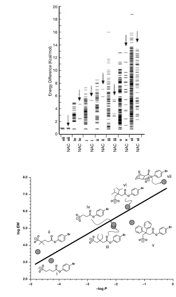
Using the energy of the 10,000–40,000 unique conformers and a Boltzmann
distribution profile, the mole fraction P of conformations present as NACs was
determined. As the inherent structural rigidity of the substrate increased, a greater
mole fraction was found to be present as NACs (Figure 1.12 (i)). This observation
meets the expectation of the original study which sought to induce the proximity
effect which would promote rate acceleration. A plot of log Pvs. the log of the EM for
each of the monophenyl esters revealed a direct linear free energy relationship
(i)
vii vii iv iv i i ii ii iii iii v v vi vi
NAC NAC NAC NAC NAC NAC NAC
0 2 4 6 8 10 12 14 16 18 20
Ener
gy Dif
fer
ence (Kcal/mol)
(ii)
–5 –4 –3 –2 –1 0
2.0 3.0 4.0 5.0 6.0 7.0 8.0
–Log P
Log
EM
vii
v vi
iv
iii ii
i
–log P
log
EM
O O O
Br
O O
O O
O O Br
O O
O
O Br
O O
O
O Br
O O
O O Br O
O O
O Br
O O O
O
[image:38.595.123.468.100.683.2]Br
Figure 1.12: ! (i) For each ester in Table 1.3, two columns of plots of differences in final energies of local
! minimum conformations relative to the lowest energy ground state are shown. The column
! above the structure label (i→vii) shows a line to represent a unique conformation. If a unique
! conformation is also a near attack conformation, this is shown by a line in the second column
! (arrows pointing to NACs). Figure adapted from reference 64 (ii) Plot of the log of the EM for
! the anhydride formation from Table 1.3 vs. the log of the mole fraction P for NAC formation.
As a result of these calculations, it was concluded that the greater the mole fraction
of NACs present in the ground state, the greater the rate constant for that reaction.
When the ground state of the substrate contains only NACs, vii, a rate acceleration of
up to 108 can be achieved. Furthermore, the log EM was found to be directly related
to the ground state enthalpy ΔH˚ and not to the change in entropy TΔS˚ from which
the observed rate accelerations in this reaction could be attributed to enthalpic and not entropic contributions.
These results from Bruice et al show that even with a great deal of time and effort
devoted to the quest to understand enzyme catalysis, a comprehensive
understanding of these rate accelerations is yet to be truly achieved. The ground
state proximity effect was only able to account for a rate acceleration of up to 108
over an uncatalysed process whereas up to 1015 has been realised in nature. Given
that enzymes have had millions of years to evolve their catalytic processes, it is
unsurprising that science lags behind attempting to replicate enzymatic ability in a
wholly synthetic system. Naturally given the remarkable efficiency of enzyme
catalysis, scientists continue to search for a deeper understanding of how enzymes
are able to achieve this efficiency and attempt to replicate it in a laboratory setting.
1.4 Templates
The practical use of natural enzymes in a synthetic laboratory setting is limited as a
result of the substrate specificity displayed by enzymes. However with an ever
growing appreciation of enzymatic processes, such as those described above in
rendering a bimolecular reaction into a pseudo intramolecular reaction to achieve
rate acceleration, rationally designed ʻartificial enzymesʼ for a particular reaction of
choice have the potential to become a highly rewarding field of research.
An outside body which is able to spatially arrange some form of material is more
commonly referred to as a template. A template conveys information in the form of
the desired structure of the product and their uses are not confined to the molecular
scale. Templates are commonly employed in building and manufacturing and whilst
these exist on a macroscopic scale, the principles for macroscopic and molecular
Figure 1.13: ! In the macroscopic construction of for example an archway, a template (in brown) may be used
! to hold blocks in place while they are fixed by cementing (black). One completed, the template
! can then be removed to leave behind the finished arch and a template which in principle may be
! recycled. Figure adapted from reference 65.
For example, when building an archway for a bridge65 (Figure 1.13) stone blocks may
be temporarily held in place by a template whilst they are fixed by cement. Once
finished, the template may be removed to leave the free standing structure. With no
change in the template throughout construction, it has the potential to be reused to
produce another arch. With this analogy it is clear to see a resemblance to enzyme
catalysis. On the molecular scale an enzyme, acting as the template, will associate
its substrate(s) promote the formation of a particular product over all others. Upon
completion, dissociation will liberate the product and enzyme which is unaltered and
able to participate in further reactions.
On the molecular stage, templates are common place in nature. Enzymes commonly
position substrates into conformations which promote reaction and the synthesis of
DNA and RNA is templated by DNA. Upon the discovery66 of the DNA double helix
structure in 1953, Watson and Crick realised that the method of its replication would
involve template directed synthesis.67 Whilst the term template is commonly used in
a variety of sciences, it is convenient to understand the distinction between a
chemical template to others. The definition of a chemical template as given by
Busch68 is:
“A chemical template organises an assembly of atoms, with respect to one or more
![Figure 1.15: �Copper template directed synthesis of a [2]catenane by Sauvage and co–workers.](https://thumb-us.123doks.com/thumbv2/123dok_us/8581645.369829/43.595.75.494.88.502/figure-copper-template-directed-synthesis-catenane-sauvage-workers.webp)