A Design of a Hybrid System for DNA Sequence Alignment
Heba Khaled, Hossam M. Faheem, Tayseer Hasan, Saeed Ghoneimy
Abstract
This paper describes a parallel algorithm and its needed architecture and a complementary sequential algorithm for solving sequence alignment problem on DNA (Deoxyribonucleic acid) molecules. The parallel algorithm is considered much faster than sequential algorithms used to perform sequence alignment; the initialization operation is done by activating a number of processing elements each compares the two sequences simultaneously and weights this comparison between each nucleotide from the first and the second DNA sequences. Then, the sequence matching operation is performed also simultaneously on the same processing elements. Both the initialization operation and the sequence matching operation are done in only two clock cycles. The proposed sequence matching operation is considered a new approach that highlights the subsequences matched between the given two DNA sequences. This operation provides a good indication for linking the matched subsequences of the two DNA sequences depending on a threshold K. which indicates the number of subsequences of highest score that can be linked. A parallel architecture is also presented as the algorithms are performed using it. A simple sequential algorithm is then presented to get the final alignment between the two DNA sequences. This hybrid system is considered a step towards a complete parallel processing architecture to solve computationally intensive applications of DNA.
Key Words: parallel processing, sequence alignment algorithms, molecular biology.
1. Introduction
Sequence comparison is one of the most fundamental problems of computational biology.
Manuscript received November 1, 2007.
Heba Khaled, Hossam M. Faheem, Saeed Ghoneimy are with the Computer System Department at Faculty of Computer & Information Science, Ain Shams University, (e-mails respectivly: [email protected], [email protected], [email protected]).
Tayseer Hasan is with the Information System Department at Faculty of Computer & Information Science, Ain Shams University, (e-mail: [email protected]).
Complexity of sequence comparison algorithms are quadratic with respect to the length of the query size and database size, which is extensively high on sequential computers [1], [2]. Database growth rate will continue by a factor of 1.5–2 every year [3].
Sequence alignment leads to identify similar functionality, to predict structural similarity and to find important regions in a genome. An alignment can be seen as a way of transforming one sequence into the other. This paper focuses on the molecular biology domain specially the DNA (Deoxyribonucleic acid) sequence databases.
Many algorithms were used to solve the sequence alignment problem like Needleman-Wunsch, Smith-Waterman, BLAST and FASTA, Suffix Trees, Hirschberg’s algorithm, Four Russian Algorithm and so on [4]-[7]. For example, Needlman Wunsch algorithm is a dynamic programming based algorithm, it finds the best global alignment for two sequences [6]. The algorithm Complexity is O (n × m) for sequence lengths n and m. Also Smith-Waterman
algorithm finds the optimal local alignment between two sequences using the technique of dynamic programming [7].
Parallel processing reduces task's execution time by solving multiple parts of the problem concurrently. Sequence alignment problem also seems to be ideally qualified to be solved using parallel processing this is because a typical process is repeated on different data items where interactions between tasks and operations are minimal.
This paper shows that the sequence alignment problem can be solved using parallel processing architectures. This can be performed by assigning a set of processing elements. These processing elements are able to decide whether there is a match between the first and the second DNA sequences nucleotides or not and then weight and focus on the matched subsequences between the two DNA sequences to be aligned. All the processing elements can perform the same operation concurrently at different positions into both DNA sequences. The number of processing elements is equal to n × m where n and m are the first
complementary sequential algorithm, by completing this step the best alignment and score can be found between the two DNA sequences.
2. DNA Sequence Alignment New parallel
and sequential Algorithm
The algorithm shown in Fig.1-a finds all the sequences of match between two DNA sequences the first sequence S of length n and the second sequence T
of length m. Given the length of the first and the
second DNA sequences, the algorithm first activates a number of processing elements (PE) equals to (n) × (m). All nucleotides from the two DNA sequences are
loaded to their corresponding PE as shown in Fig.2. All the PEs perform the exact matching between the corresponding first sequence nucleotide and second sequence nucleotide simultaneously as a first step which is called the initialization process. The PEs then performs the sequence matching process that weights any sequence of match between the two DNA sequences according to set of rules listed below. The sequence matching process is done simultaneously and the result of each PE is then stored in n Match Register (MR) each of size equals m at a position relevant to the PE.
The algorithm shown in Fig.1-b first creates a table of indices as shown in Fig. 3, which contains a list of matched subsequences represented by the lead and the trail of each matched subsequence and its score. The matched subsequence score is equal to the number of matched cells multiplied by 2. A preprocessing step is then done to discard the very small subsequences of score equal 2 “only one match” from the table of indices and then sort the entries of the matched subsequences using merge sort. The user can specify a merging threshold K that indicated the longest
common subsequences between the two DNA sequences. The algorithm then merges the entries in the table of indices “matched subsequences” according to set of rules listed in Fig.1-b. The merging operation’s complexity is O (K N) where K is a
constant representing the merging threshold and N is
the size of the table of indices. After the merging process the alignment of maximum score can be found.
Parallel Part:
Given two DNA sequences S of length n, and T of length m:
1- Activate n × m PE (processing element) 2- For each PE:
Load a nucleotide from the first sequence and a nucleotide from the second sequence.
Sequential Part:
1- Apply merge sort to the results given from the parallel part that sorts the subsequences descending according to their score “A preprocessing step”.
2- Discard small subsequences of score equal 2.
3- Create table of indices according to the sorted subsequences.
4- Given that Each entry “aligned subsequence” in the table of indices has a lead and trail and each has i and j coordinates such that:
iL
Is the i coordinate of the first subsequence’s Trail, Is the
Is the j coordinate of the first subsequence’s lead, i coordinate of the first subsequence’s lead,
jL T i
T
j Is the j coordinate of the first subsequence’s Trail,
iL Is the i coordinate of the second subsequence’s lead, jL Is the j coordinate of the second subsequence’s lead,
’
iT Is the i coordinate of the second subsequence s Trail,
Is th d subsequence’s jT e j coordinate of the secon
Trail,
irst s equ e’s e, Score S = F ubs enc scor Score S = Second subsequence’s score.
M_G = max[(iL − iT ), (jL − jT )]=Gaps and/or Mismatches between the two subsequences,
Given a threshold K indicating how many subsequence to be merged with the whole entries in the table of indices,
he s e ue the le o ces accordin Merge t ubs q nces in tab f indi g to the following rules:
IF ( (( i == i AND j < j )OR
T L T L
( jT == jL AND iT < iL ) AND M
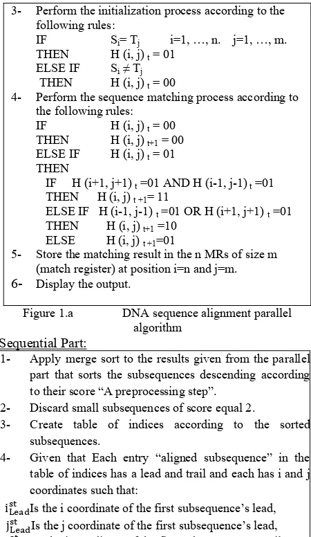
3- Perform the initialization process according to the following rules:
IF Si= Tj i=1, …, n. j=1, …, m. THEN H (i, j) t = 01
ELSE IF Si≠ Tj THEN H (i, j) t = 00
4- Perform the sequence matching process according to the following rules:
IF H (i, j) t = 00 THEN H (i, j) t+1 = 00 ELSE IF H (i, j) t = 01 THEN
IF H (i+1, j+1) t =01 AND H (i-1, j-1) t =01 THEN H (i, j) t +1= 11
ELSE IF H (i-1, j-1) t =01 OR H (i+1, j+1) t =01 THEN H (i, j) t+1 =10
ELSE H (i, j) t +1=01
5- Store the matching result in the n MRs of size m (match register) at position i=n and j=m.
[image:2.612.316.541.70.458.2]6- Display the output.
Figure 1.a DNA sequence alignment parallel algorithm
)
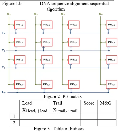
Figure 2 PE matrix
Figure 3 Table of Indices Lead
Xi lead
,
j leadTrail Xi trail
,
j trailScore M&G
1
2
3. Organization
The organization of the proposed system is shown in Fig. 4. It consists of an input unit, control unit, and an output unit. The input unit has an input device that accepts the first and the second DNA sequence arrays. Each of the two arrays is stored into a one dimensional array. Each sequence will be stored into an input array of a number of positions equal to the input sequence length stored in it and each position has 2 flip flops A
and B. Table I shows the binary representation of
different basic DNA molecules. The first and second sequences are passed to the processing elements (PEs) after the control unit activates them. The PEs then
perform the initialization process in one clock cycle and then the sequence matching process also in only one clock cycle. Each PE then provides its decision to its corresponding bit into the match registers (MRs). All the PEs perform the same operation simultaneously. The data stored into the MRs is then passed to a decoding circuitry and then to an output device to display results.
4. Architecture
The PE performs two operations, first the initialization operation then the sequence matching operation, a block diagram of the PE is shown in Fig.5-a. At the initialization operation the PE acts as a 2-bit binary comparator used to compare the four
DNA nu eo . ion that describes
this ope n is:
cl tides The logical funct ratio
𝑀, = (𝑎 ⊙ 𝑎 ) (𝑏 ⊙ 𝑏 ) (1)
The internal structure is shown in Fig.5-b. The sequence matching operation’s output indicates the matched sequences occurred between the two DNA sequences. The internal structure is shown in Fig.5-c. Seq en atch ar ighted according to the logi l
u ces of m e we a i hown ble II;
(2)
c funct on s in Ta
𝑅 = 𝑀, (𝑀 , + 𝑀 , )
𝑅 = 𝑀, (𝑀 , ⨀ 𝑀 , ) (3)
THEN
Total score= Score S + Score S − M G− 2
))AND ELSE IF ( < 𝑖 ) AND (jT < 𝑗L
ND ((iT L
((M_G − 1) < Score S ) A < Sc S )
((M_G − 1) ore ) THEN
Total score=Score S + Score S − (M G− 1) 5- Add the merged subsequences to the table.
6- After a round of merging and getting new subsequences, delete from the table of indices the g each ne first subsequence used in marginin w subsequence.
- Go to 3 “another round of margining”.
If there is nothing to be merged then select the sequence of maximum score and minimum gap and mismatches.
[image:3.612.64.294.56.556.2]7
[image:3.612.315.538.168.386.2]Figure 1.b DNA sequence alignment sequential algorithm
Figure 4 Parallel Organization
Input Unit
First Sequence
Second Sequence
Input Device
Control Unit
Processing
Elem
ents
Output Unit
Match register
Decoding circuitry
Output Device
Table I DNA Molecules Binary Representation
G 0 0
0 1 1 0 1 1
A A B Nucleotide
C T
[image:3.612.71.296.290.540.2] [image:3.612.333.519.573.700.2]0
1 0 Mi, j At t
… 01
… Mi,j At t+1
Mi,j At t+1
11 Mi, j At t
1 1
1
Case 1: Current cell value Mi, j = 0
After sequence matching ⟹ Mi, j = 00 “no change”.
M M At
. . . .
. . 0 . .
. . . .
. . . .
. . 00 . .
. . . .
i,j At t i,j t+1
Case 2:
Current cell value Mi, j=1 d has no diagonal cells=1
Mi-1,j-1 and Mi+1,j+1 ≠1
an
After sequence matching ⟹ Mi, j = 01.
Case 3:
Current cell value Mi, j=1 has one diagonal cell M i-1,j-1 or Mi+1,j+1 =1
and
After sequence matching ⟹Mi, j = 10.
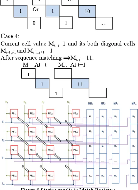
Case 4:
Current cell value Mi, j= nd its both diagonal cells
Mi-1,j-1 and Mi+1,j+1 =1
1 a
After sequence matching ⟹Mi, j = 11.
Processing of the first DNA sequence S and the second DNA sequence T is performed simultaneously. The overall operations are carried out in two clock cycles one for the initialization operation and the other for the sequence matching operation. Consequently, n × m positions of the MRs hold the result R0R1from the
PE as shown in Fig. 6.
5. Operation
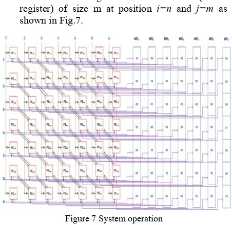
In order to explain the operation of the proposed system, let us consider an example; perform sequence alignment on the given two DNA sequences S= T1C2G3C4A5G6A7 and T= T1C2C3A4C5G6A7 . The
operation shown in Fig.7, Table III and Table IV can be summarized as follows:
• Activate (n)*(m) PE where n is the first sequence
length and m is the second sequence length. • For each PE load a nucleotide from the first
sequence and a nucleotide from the second sequence.
• Perform the initialization and the sequence matching processes according to the rules stated in the parallel algorithm shown in Fig. 1-a.
Mi, j At t M At i,j
Mi-1,j-1 Mi,j Mi+1,j+1 R0 R1
0 0 0 0 0
0 0 1 0 0
0 1 0 0 1
0 1 1 1 0
1 0 0 0 0
1 0 1 0 0
1 1 0 1 0
1 1 1 1 1
Table II scoring the matched sequence
Case 1
Case 1 Case 2
Case 3
Case 4
Or 0
1 …
1
1 10
(b) Initialization Operation
1
0 …
[image:4.612.63.296.63.690.2] [image:4.612.314.540.108.419.2](c) Sequence Matching Operation Figure 5 Processing Element
• Store the matching result in the n MRs (match
register) of size m at position i=n and j=m as
shown in Fig.7.
• Use the decoding circuitry to display the initial entries of the table of indices as shown in Table III.
• A preprocessing step is performed to discard very small subsequences of score equal 2 and sort the entries of the table of indices descending according to their score using merge sort as shown in Table IV.
[image:5.612.69.290.65.719.2]• Merge the subsequences in the table of indices given a threshold indicating how many subsequence is used in merging with the whole entries of the table of indices according to the rules stated in the sequential algorithm shown in Fig. 1-b and add the merged subsequences to the table.
• Repeat the merging operation and if there is nothing to be merged then select the sequence of maximum score and minimum gap/mismatches. • The resulted tables of indices is shown in Table V
given threshold K=1.
• The best alignment starts at lead (0, 0) and ends with the trail (6,6) with score equals 10 and Gap/Mismatch equals 2 which is indicated at sequence number 0 at the final round in the table of indices.
ID
Subsequence
&
Subsequence
Lead Tra
il
Sc
ore
Gap&
Misma
tc
h
Next Round
0 0&2 (0,0) (4,3) 7 1
1 0&3 (0,0) (6,6) 5 3
2 _ (1,4) (2,5) 4 0
3 2 (3,2) (4,3) 4 0
4 3 (5,5) (6,6) 4 0
Next Round
0 0&4 (0,0) (6,6) 10 2
1 0&3 (0,0) (6,6) 5 3
2 _ (1,4) (2,5) 4 0
3 2 (3,2) (4,3) 4 0
4 4 (5,5) (6,6) 4 0
6. Results
It is obvious that as the DNA sequences’ size increases, the number of the required PEs increases. Also, the number of PEs decreases as the DNA sequences’ size decreases. In the parallel part, clock cycle time can be considered as the sum of PE activation time, time needed for data to enter the PE, the time taken by a PE to perform the comparison and scoring processes, and time needed to store results into the MRs. A typical macro-scale implementation for a processing element in the previously explained example is shown in Fig.8. A typical time of 58.5ns is achieved.
The parallel algorithm execution time is the clock cycle time 58.5 ns. The sequential algorithm execution time can be calculated for different thresholds as shown in Table VI on a 1.83 GHz Intel Centrino Duo, 2 GB of RAM. The total execution time for the hybrid
[image:5.612.71.297.82.302.2]Table V Completed rounds in the table of indices at K=1
Figure 7 System operation
Table III Initial table of indices
ID
Subsequence
&
Subsequence
Lead Tra
il
Sc
ore
Gap&
Misma
tc
h
0 _ (0,0) (1,1) 4 0
1 _ (1,4) (2,5) 4 0
2 _ (3,2) (4,3) 4 0
3 _ (5,5) (6,6) 4 0
4 _ (1,2) (1,2) 2 0
5 _ (3,1) (3,1) 2 0
6 _ (3,4) (3,4) 2 0
7 _ (4,6) (4,6) 2 0
8 _ (6,3) (6,3) 2 0
ID
Subsequence
&
Subsequence
Lead Tra
il
Sc
ore
Gap&
Misma
tc
h
0 _ (0,0) (1,1) 4 0
1 _ (1,4) (2,5) 4 0
2 _ (3,2) (4,3) 4 0
3 _ (5,5) (6,6) 4 0
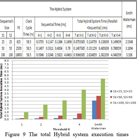
[image:5.612.318.521.90.486.2]system is the summation of the parallel algorithm and the sequential algorithm execution times.
Fig. 9 shows the Hybrid System execution time for different thresholds and different DNA sequence sizes. For a fixed size PEs, DNA sequences of sizes more than 100 characters will be treated as segments each of 100 characters. Hence, the clock cycles’ time required will be: (Clock Cycle time for one Segment) × (# of Segments) and the total sequential time will be the
summation of all the segments execution time.
7. Application
The following application applies the sequential and the parallel algorithms, finds the final alignment and the sequential algorithm execution time at different threshold entered by the user. As shown in Fig. 10, the parallel form allows the user to insert two different DNA sequences; the Create Matrix button performs the initialization process of the parallel algorithm. The Scoring button performs the sequence
matching process and the output at the MRs after decoding is shown in the second data grid. The Index Table button creates the initial table of indices represented by the lead and the trail of each matched subsequence and its score.
[image:6.612.320.534.132.271.2]Figure 8 A typical macro-scale Processing Element Table VI Required PEs to perform DNA sequence alignment, the Hybrid system and Smith waterman execution times for different sequence sizes
Figure 10 Parallel form
As shown in Fig. 11, a preprocessing step is then done by choosing the Discard Small Subsequences button to discard the very small subsequences and then sort the entries of the matched subsequences. The user can specify a merging threshold K. The algorithm then merges the entries in the table of indices “matched subsequences” by clicking on the Complete Rounds button. After merging, the alignment of maximum score and the total sequential execution time can be calculated by clicking the Final Sequence button.
Figure 9 The total Hybrid system execution times required to perform DNA sequence alignment for different sequence sizes and thresholds
8. References
Figure 11 Sequential form
[1] J. Setubal and J. Meidanis, Introduction to Computational Molecular Biology, PWS Publishing Company, 1997.
[2] Terence Hwa and Michael Lässig, “Similarity Detection and Localization”.
[3] Dominique Lavenier, “Speeding up Genome Computations with
a Systolic Accelerator”, July 18 2001.
[4] Ron Shamir, “Algorithms for Molecular Biology”, Algorithms in Molecular Biology Lecture 3, School of Computer Science, Tel Aviv University, 2001.
[5] Marcelam Miyazawa, “Sequence Alignment/Linear Space Alignment/Four Russian Algorithm”, CS262: Computational genomics, 2005.
[6] S. Needleman and C.Wunsch, “A general method applicable to the search for similarities in the amino acid sequence of two proteins”. J. Mol. Bio., (48):443–453, 1970.
[image:6.612.75.296.247.468.2] [image:6.612.317.533.394.525.2]