Methodology of PID Control – A Case Study for Stepper
Motors
M. Papoutsidakis
Dept. of Automation Eng,
Piraeus University of Applied Sciences
Athens, Greece
A. Chatzopoulos
Dept. of Automation Eng,
Piraeus University of Applied Sciences
Athens, Greece
E. Symeonaki
Dept. of Automation Eng,
Piraeus University of Applied Sciences
Athens, Greece
D. Tseles
Dept. of Automation Eng,
Piraeus University of Applied Sciences
Athens, Greece
ABSTRACT
Stepper motors have already shown their advantages of use in applications where precision movements and accurate control are required. One of the most commonly used type of controller that was used to control stepper motors is the classical PID controller because of its easily programming characteristics. In this paper such a conjunction is going to be presented and as well as all the results of a given example of application.
Keywords
Stepper motor, classical controllers, PID method, three terms tuning
1.
INTRODUCTION
In this report we will be talking about stepper motors and PID – controllers and try to understand how they work and why and where they are used.
2.
STEPPER MOTORS
Stepper motor is a brushless DC electric motor that divides a full rotation into a number of equal steps. Brushed DC motors rotate continuously when DC voltage is applied to their terminals. The stepper motor is known by its ability to convert a train of input pulses (typically square wave pulses) into a precisely defined increment in the shaft position. Each pulse moves the shaft through a fixed angle.
[image:1.595.345.500.305.634.2]Stepper motors effectively have multiple "toothed" electromagnets arranged around a central gear-shaped piece of iron. The electromagnets are energized by an external driver circuit or a micro controller. To make the motor shaft turn, first, one electromagnet is given power, which magnetically attracts the gear's teeth. When the gear's teeth are aligned to the first electromagnet, they are slightly offset from the next electromagnet. One of the benefits of a stepper motor is that it is a simple, accurate and doesn’t need closed feed back system.
Fig. 1. Open loop control system
There are three main types of stepper motors:
-Permanent magnet stepper
-Hybrid synchronous stepper
-Variable reluctance stepper
These motors differ from each other regarding their structure and how they control. Stepper motors usually use unipolar or bipolar directing methods. Stepper motors suit especially well for computer or logic controller, because controlpulses have to states.
Fig. 2. Bipolar directing method
Fig. 3. Unipolar directing method
2.1
Full step drive
Full Step drive can be done with only one phase on or two phases on. When one phase method isused, only a single phase will be activated at a time. It has the same amount of steps as the two phase method, but the motor will have significantly less than rated torque. It is rarely used.
[image:1.595.86.259.625.686.2]35 are both one and the same, with same number of steps but
difference in torque.
2.2
Half-stepping
When half-stepping, the drive alternates between two phases on and a single phase on. This increases the angular resolution. The motor also has less torque (approx 70%) at the full-step position (where only a single phase is on). This may be mitigated by increasing the current in the active winding to compensate. The advantage of half stepping is that the drive electronics need not change to support it.
2.3
Microstepping
What is commonly referred to as microstepping is often sine– cosine microstepping in which the winding current approximates a sinusoidal AC waveform. Sine–cosine microstepping is the most common form, but other waveforms can be used. Regardless of the waveform used, as the microsteps become smaller, motor operation becomes more smooth, thereby greatly reducing resonance in any parts the motor may be connected to, as well as the motor itself. Resolution will be limited by the mechanical stiction, backlash, and other sources of error between the motor and the end device. Gear reducers may be used to increase resolution of positioning.
2.4
Variable reluctance stepper
Just as resistance determines the flow of electric current, reluctance determines the flow of magnetic flux. In a variable reluctance (VR) stepper, the rotor turns at a specific angle to minimize the reluctance between opposite windings in the stator.
The primary advantage of VR steppers is that they have excellent angular resolution. The primary disadvantage is low torque.
Structurally speaking, variable reluctance (VR) steppers have a lot in common with PM steppers. Both have windings on their stator and opposite windings are connected to the same current source.
However, there are two primary differences between VR steppers and PM steppers:
Rotor: Unlike a permanent magnet stepper, the rotor in a VR stepper doesn’t have magnets. Instead, the rotor is an iron disk with small protrusions called teeth.
Phases: In a permanent magnet stepper, the controller energizes windings in two phases. For a VR stepper, the controller energizes every pair of opposite windings independently. In other words, if the stator has N windings, it receives N/2 signals from the controller.
[image:2.595.313.538.195.328.2]
Fig. 4. When current is directed to different coils (1, 2 and 3 in a specific order) we achieve continuous movement
of the motor.
2.5
Permanent magnet stepper
Permanent Magnet (PM) motors use permanent magnet rotors and are commanded by electrical pulses. They are widely used in
printers, copies, and scanners, among other applications. They are also used to operate valves in household water and gas systems as well as drive actuators in automotive applications.
[image:2.595.321.544.570.695.2]One of the main benefits of the PM stepper motor is that, in addition to being electronically commutated like a brushless DC motor or any other type of stepper motor, the PM stepper motor requires no “teeth” as are typically found in the variable reluctance (VR) stepper motor. This makes the permanent magnet stepper an extremely popular choice for many motor applications.
Fig. 5. In the rotor of permanent magnet motor the metallic teeths have been replaced with permanent
magnet
2.6
Hybrid synchronous stepper
A hybrid (HY) stepper provides the best of both worlds. Like a PM stepper, its rotor has magnets that provide torque. Like a VR stepper, the rotor has teeth that improve the angular resolution. Hybrid motors have two disadvantages. First, HY steppers can be significantly more expensive than PM steppers. Second, HY steppers are larger and heavier than PM steppers.
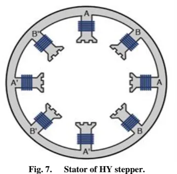
Hybrid steppers rotors and stators are different from those of either stepper type (VR and PM), but the principle of their operation is similar.
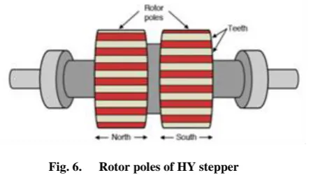
[image:2.595.71.287.609.696.2]HY stepper rotor has (at least) two rotating mechanisms connected to one another. These are called rotor poles. The rotor poles are magnetized so that one behaves like a north pole and one behaves like a south pole. Each pole has its own teeth, and the teeth of one rotor pole are oriented between those of the other. The angular difference between the two sets of teeth determines the step angle of the motor. The more teeth the stepper has, the better the angular resolution.
Fig. 6. Rotor poles of HY stepper
Fig. 7. Stator of HY stepper.
Table 1 show the peak signal to noise ratio of performance of our proposed method of watermarked image and original image with various watermark image, where our watermarked images peak signal to noise ratio has a better performance than others.
3.
P, PI and PID controllers
The ability of proportional (P), proportional integral (PI) and proportional integral derivative (PID) controllers to compensate most practical industrial processes has led to their wide acceptance in industrial applications. For example, it has been suggested that there are perhaps 5- 10% of control loops that cannot be controlled by single input, single output (SISO) P, PI or PID controllers. In particular, these controllers perform well for processes with benign dynamics and modest performance requirements. Almost 100% of control loops in the pulp and paper industries are controlled by SISO PI controllers and that, in process control applications, more than 95% of the controllers are of PID type. The PI or PID controller implementation has been recommended for the control of processes of low to medium order, with small time delays, when parameter setting must be done using tuning rules and when controller synthesis is performed either once or more often. However, despite decades of development work, surveys indicating the state of the art of control industrial practice report sobering results. The situation does not appear to have improved in recent years because it has been reported that 80% of PID controllers are badly tuned. The most direct way to set up controller parameters is the use of tuning rules. Obviously, the wealth of information on this topic available in the literature has been poorly communicated to the industrial community.
3.1
PID controller
[image:3.595.315.534.542.655.2]PID-controllers are by far the most popular controllers. In process control over 95% are PID_type. One of the main reasons for such a wide popularity is that they are relatively easy to use and understand. Today most of the PID-controllers are microprocessor based and often these are integrated directly into actuators like valves or servos.
Fig. 8. Fig. 8.Classic block diagram of a process under PID control
The basic idea behind a PID controller is to read a sensor, then compute the desired actuator output by calculating proportional, integral and derivate responses and summing those three components to compute the output.
In a typical control system, the process variable is the system parameter that needs to be controlled, such as temperature (ºC), pressure (psi), or flow rate (liters/minute). A sensor is used to measure the process variable and provide feedback to the control system. The set point is the desired or command value for the process variable, such as 100 degrees Celsius in the case of a temperature control system. At any given moment, the difference between the process variable and the set point is used by the control system algorithm (compensator), to determine the desired actuator output to drive the system (plant). For instance, if the measured temperature process variable is 100 ºC and the desired temperature set point is 120 ºC, then the actuator output specified by the control algorithm might be to drive a heater. Driving an actuator to turn on a heater causes the system to become warmer, and results in an increase in the temperature process variable. This is called a closed loop control system, because the process of reading sensors to provide constant feedback and calculating the desired actuator output is repeated continuously and at a fixed loop rate.
In many cases, the actuator output is not the only signal that has an effect on the system. For instance, in a temperature chamber there might be a source of cool air that sometimes blows into the chamber and disturbs the temperature. Such a term is referred to as disturbance. We usually try to design the control system to minimize the effect of disturbances on the process variable.
The control design process begins by defining the performance requirements. Control system performance is often measured by applying a step function as the set point command variable, and then measuring the response of the process variable. Commonly, the response is quantified by measuring defined waveform characteristics. Rise Time is the amount of time the system takes to go from 10% to 90% of the steady-state, or final, value. Percent Overshoot is the amount that the process variable overshoots the final value, expressed as a percentage of the final value. Settling time is the time required for the process variable to settle to within a certain percentage (commonly 5%) of the final value. Steady-State Error is the final difference between the process variable and set point. Note that the exact definition of these quantities will vary in industry and academia.
Fig. 9. Response of a typical PID closed loop system
3.2
PI controller
[image:3.595.59.290.654.741.2]37
Fig. 10. PI control loop
[image:4.595.68.277.223.373.2]Integral action eliminates steady state error. However, it has very poor transient response. Using integral action increases the oscillations in the output of the closed loop systems. The discussion above indicates that with PI control, steady state error is non-zero. However, Integral control causes too many oscillations in closed loop system outputs.
Fig. 11. Response of a typical PI controller
3.3
P controller
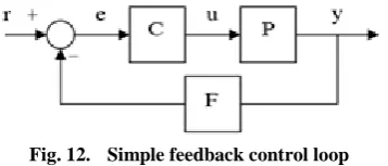
In engineering and process control, Proportional control is a type of linear feedback control system in which a correction is applied to the controlled variable which is proportional to the difference between the desired value (set point, SP) and the measured value (process value, PV). Two classic mechanical examples are the toilet bowl float proportioning valve and the fly-ball governor.
The proportional control concept is more complex than an on– off control system like a bi-metallic domestic thermostat, but simpler than a proportional–integral–derivative (PID) control system used in something like an automobile cruise control. On– off control will work where the overall system has a relatively long response time, but can result in instability if the system being controlled has a rapid response time. Proportional control overcomes this by modulating the output to the controlling device, such as a control valve at a level which avoids instability, but applies correction as fast as practicable by applying the optimum quantity of proportional gain.
Fig. 12. Simple feedback control loop
As a general rule, increasing proportional gain decreases the steady state error. However, the actual performance of P controller depends on the order of the plant. If P controller is used to control a second order plant, it has following properties:
- Increasing gain decreases rise time (Advantage)
- Increasing gain increases percent overshoot and number of oscillations (Disadvantage)
- Increasing gain decreases steady state error (Advantage)
- Steady state is never zero if only-P type controller is used (Disadvantage)
- In order to have zero steady state error gain should be infinity (Physically impossible)
The discussion above shows that only-P control is not enough to control second order plants. In fact, only-P control is usually used to control first order plants, because there are no natural oscillations in first order plants and P control is easy to implement.
4.
ACKNOWLEDGMENTS
All authors would like to express their gratitude to the Post-Graduate Program of Studies “Automation of Productions and services” of PUAS, for the financial support to undertake this research project
5.
REFERENCES
[1] B. Corona, M. Nakano, H. Pérez, “Adaptive Watermarking Algorithm for Binary Image Watermarks”, Lecture Notes in Computer Science, Springer, pp. 207-215, 2004.
[2] A. A. Reddy and B. N. Chatterji, "A new wavelet based logo-watermarking scheme," Pattern Recognition Letters, vol. 26, pp. 1019-1027, 2005.
[3] P. S. Huang, C. S. Chiang, C. P. Chang, and T. M. Tu, "Robust spatial watermarking technique for colour images via direct saturation adjustment," Vision, Image and Signal Processing, IEE Proceedings -, vol. 152, pp. 561-574, 2005.
[4] F. Gonzalez and J. Hernandez, " A tutorial on Digital Watermarking ", In IEEE annual Carnahan conference on security technology, Spain, 1999.
[5] D. Kunder, "Multi-resolution Digital Watermarking Algorithms and Implications for Multimedia Signals", Ph.D. thesis, university of Toronto, Canada, 2001.
[6] J. Eggers, J. Su and B. Girod," Robustness of a Blind Image Watermarking Scheme", Proc. IEEE Int. Conf. on Image Proc., Vancouver, 2000.
[7] Barni M., Bartolini F., Piva A., Multichannel watermarking of color images, IEEE Transaction on Circuits and Systems of Video Technology 12(3) (2002) 142-156.
[8] Kundur D., Hatzinakos D., Towards robust logo watermarking using multiresolution image fusion, IEEE Transcations on Multimedia 6 (2004) 185-197.
[9] C.S. Lu, H.Y.M Liao, “Multipurpose watermarking for image authentication and protection,” IEEE Transaction on Image Processing, vol. 10, pp. 1579-1592, Oct. 2001. [10]L. Ghouti, A. Bouridane, M.K. Ibrahim, and S. Boussakta,
“Digital image watermarking using balanced multiwavelets”, IEEE Trans. Signal Process., 2006, Vol. 54, No. 4, pp. 1519-1536.
[image:4.595.84.263.609.685.2][12]P. Kumswat, Ki. Attakitmongcol and A. Striaew, "A New Approach for Optimization in Image Watermarking by Using Genetic Algorithms", IEEE Transactions on Signal Processing, Vol. 53, No. 12, pp. 4707-4719, December, 2005.
[13] H. Daren, L. Jifuen,H. Jiwu, and L. Hongmei, "A DWT-Based Image Watermarking Algorithm", in Proceedings of the IEEE International Conference on Multimedia and Expo, pp. 429-432, 2001.
[14]C. Hsu and J. Wu, "Multi-resolution Watermarking for Digital Images", IEEE Transactions on Circuits and Systems- II, Vol. 45, No. 8, pp. 1097-1101, August 1998. [15]R. Mehul, "Discrete Wavelet Transform Based Multiple