ISSN Online: 2161-7589 ISSN Print: 2161-7570
DOI: 10.4236/ojg.2018.86036 Jun. 21, 2018 623 Open Journal of Geology
Semi-Deep
Skirted
Foundations
and
Numerical
Solution
to
Evaluate
Bearing
Capacity
Keivan
Esmaeili,
Abolfazl
Eslami,
Samiyeh
Rezazadeh
Department of Civil and Environmental Engineering, Amirkabir University of Technology (Tehran Polytechnic), Tehran, Iran
Abstract
Semi-deep foundations are a remarkable solution in conditions where the soil beneath the foundation is loose to a great depth and there is no possible way to use any way of soil improvement and applying piles would not be a logical way considering their cost and time of enforcing. Skirted foundations are a type of semi-deep foundations that can penetrate to the soil up to two times of their breadth. Estimating bearing capacity of these foundations is a long geo-technical problem for engineers whether under absolute or combined loading because of their usage in offshore and onshore projects. For estimating the vertical bearing capacity of these foundations, series of finite element analyses were performed for a range of embedment ratios to investigate the effect of the length of the skirt. The foundation has been modelled with two different types of soil and the results validated with previous analytical, numerical and experimental researches. In addition, the bearing capacity of a skirted
founda-tion under combined loading in V-H space has been analyzed by this
ap-proach and the 2-dimentional failure envelope has been presented.
Keywords
Semi-Deep Foundation, Bearing Capacity, Load-Displacement Curve, Embedment Depth Ratio, Failure Envelope
1.
Introduction
One of the most important stages of designing structures is analyzing and calcu-lating the foundation of them. Foundation is the inductor element that the duty of transferring load from substructure to soil is on it. Therefore, it can be rea-lized that foundation is the most vital part of a structure. Optimal design and analysis of a foundation consist of five basic requirements such as:
1) Determining bearing capacity
How to cite this paper: Esmaeili, K., Esla-mi, A. and Rezazadeh, S. (2018) Semi-Deep Skirted Foundations and Numerical Solu-tion to Evaluate Bearing Capacity. Open Journal of Geology, 8, 623-640.
https://doi.org/10.4236/ojg.2018.86036
Received: March 28, 2018 Accepted: June 18, 2018 Published: June 21, 2018
Copyright © 2018 by authors and Scientific Research Publishing Inc. This work is licensed under the Creative Commons Attribution International License (CC BY 4.0).
http://creativecommons.org/licenses/by/4.0/
DOI: 10.4236/ojg.2018.86036 624 Open Journal of Geology
great projects because of their disability in supplying enough bearing capacity and their non-uniform settlement under massive pressures and forces.
Unlike the shallow foundations, deep foundations or piles are so applicable for great projects because they can penetrate into the soil more than ten times of their breadth, however, these foundations have some disadvantages as well. Piles have high expenses and their installing and enforcing is extremely time-consuming.
In this paper, an intermediate solution has been presented, which is hybrid or semi-deep foundations that can penetrate up to four times of their breadth into the soil. Therefore, they can improve the bearing capacity and fix most require-ments of optimizing foundation design.
Skirted foundations are one of the most applicable semi-deep foundations in onshore projects and oil and gas and other industries. To evaluate their bearing capacity, a numerical approach with finite element analysis is suggested in this paper. To calculate the bearing capacity of a skirted foundation under combined loading, fist it is needed to realize what would happen to these foundations un-der absolute vertical loading. The parameters that affect the bearing capacity should be investigated to estimate the amount of bearing. The foundation’s geometry especially the amount that skirt penetrate into the soil is the most con-sidering parameter that affects the bearing capacity of the foundation because it would pass the soft layers of the soil and reach to the layers with acceptable roughness.
Several analytical, numerical and experimental researches have been carried out in last two decades by different researchers on bearing capacity of skirted foundations under absolute and combined loading such as: upper and lower
bound analyses by Bransby & Randolph (1999) [1], finite element analyses and
centrifuge test by Yun & Bransby (2007) [2], skirted foundations in plane strain
by Gourvenec (2008) [3] and finite element and upper bound plasticity analyses
by Eslami & Rezazadeh (2017) [4].
DOI: 10.4236/ojg.2018.86036 625 Open Journal of Geology
soil with incremental shear strength with depth. In addition, the bearing capacity of the skirted foundation under combined loading has been analyzed by finite
element method in uniform soil in V-H space in order to present a failure
envelope.
2.
Semi-Deep
Foundations
These foundations are used to apply for better transfer of load and passing through soft and loose layers of soil surface by penetrating into the soil down to
two or four times of the breadth of the foundation (Df = 2B − 4B). They will
im-prove the foundation capacity and decrease settlement. In this paper, it is aimed to express types of these foundations and investigate on their properties.
2.1.
Floating
Foundations
Floating foundations are one of the considerable improvements in optimizing the foundations in the last decades that consist of placing the footing into the depth of the soil with or without pile that cause better performance in bearing
capacity and settlement (Golder (1976) [5]). In cases where the substructure is
heavier and have a particular importance, the foundation system should have a particular bending rigidity. When the soft soil deposits with high prone to set-tlement form the layers of soil up to relatively high depth and there is not any
possible way to use pile, floating foundations are a good solution (Figure 1).
2.2.
Well
Foundations
In cases that using any ways of soil improvement for amending the soil condi-tion is impossible, well foundacondi-tions could be used. For implementing a well foundation, a hollow shaft or a box will submerge into the ground until it
reach-es to a rough layer of the soil (Gupta (2007) [6]). To make the merging of the
box to the soft soil easier, cutting edge will improvise below the box. After lying the lower edge on the rough layer, the materials inside the box will be unloaded
and then concreting it after putting the armature rack into it (Figure 2).
2.3.
Pier
Foundations
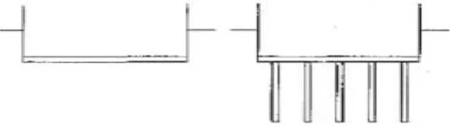
[image:3.595.211.536.614.707.2]Pier foundations or Bucket foundations or Cassions are actually in place con-crete piles that their diameter is more than 750 millimeters and in some cases, it reaches even a few meters. These foundations do not have the problems of
DOI: 10.4236/ojg.2018.86036 626 Open Journal of Geology
[image:4.595.209.537.65.238.2]
Figure 2. Details of a well foundation.
enforcing driven piles such as much noise and relocating soil. Other significant benefit of these foundations is that they can bear the great tensile and lateral forces because of their roughness and big diameter. These foundations could be installed with suction system. Suction will increase the effective stress and finally
the shear strength of the soil (Saleh (2008) [7], Barari (2012) [8], Ibsen (2015)
[9]) (Figure 3).
2.4.
Spudcan
and
Jack-Up
The great circular Spudcans with the floating platforms that is called Jack-up are one of the most useful foundations in offshore industries. These foundations can penetrate several diameters into the soft seabed deposits that cause their differ-ence in failure mechanism and bearing capacity in comparison with surface footings (Figure 4).
2.5.
Pile-Raft
Foundations
This type of semi-deep foundations is consist of a raft footing along with a pile or group of piles. Typically, these foundations are categorized in two groups. The first group is the raft relies on the pile or piles that is in most conditions that raft foundations have settled directly on the soil surface and the other is the raft that reinforced with pile and piles that is used when the soil at surface layers is so loose and the raft part faces with additional settlements. This is the time that piles should help raft in bearing loads. Pile-raft foundations have four important interaction systems including; raft with pile group, raft with soil, piles with soil,
and piles with each other (Mekbib (2004) [12], Davis (1972) [13], Eslami (2011)
[14]) (Figure 5).
2.6.
Skirted
Foundations
DOI: 10.4236/ojg.2018.86036 627 Open Journal of Geology
Figure 3. View of a suction bucket (Zhang (2010) [10]).
Figure 4. Schematic of a Spudcan and Jack-up system in offshore industries (Hambly (1985) [11]).
the breadth of the foundation (D/B = 2), they will improve the foundation
ca-pacity and by confining the surrounding soil and forming a soil block between the skirts, they will increase the strength of the foundation. Actually, the soil block can act as a rigid body and take part in bearing the pressures and loads from the substructure. These foundations are becoming an extremely prevalent
offshore foundation solution for the oil and gas industries (Byrne (2003) [17],
[image:5.595.212.517.309.574.2]DOI: 10.4236/ojg.2018.86036 628 Open Journal of Geology
Figure 5. A pile-raft system (Hemsly (2000) [15], Eslami (2012) [16]).
[image:6.595.233.520.452.706.2]DOI: 10.4236/ojg.2018.86036 629 Open Journal of Geology
3.
Finite
Element
Analysis
3.1.
Geometry
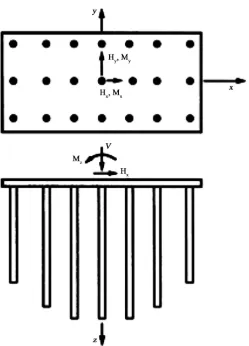
The axisymmetric finite element analysis were performed for the purpose of this study. The model comprises a circular skirted foundation with the breath, B, and depth of, D. In order to observe the different skirt length, a group of embedment ratios (D⁄B = 0.2, 0.3, 0.5, 0.75, 1, 1.2 and 2) were considered in analysis.
For all the analysis, the PLAXIS 2016 finite element software was used. This software is functioning for both offshore and onshore infrastructures and enables us to model advanced materials with different loading conditions of the soil encountered in foundation works.
3.2.
Soil
Model
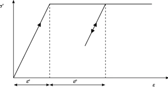
The soil was defined by a linear elastic-perfectly plastic Mohr-Coulomb model,
which represents a first-order approximation of soil behavior (Figure 7). The
type of drainage is undrained in a way that, stiffness is modelled using an
un-drained Young’s modulus Eu and an undrained Poisson ratio υu, and strength is
modelled using an undrained shear strength su and φu = 0. Excess pore pressures
are not explicitly calculated, but are included in effective stresses. Therefore, in that case the Mohr-Coulomb failure criterion reduces to the well-known Tresca criterion.
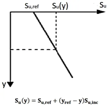
In the elastic regime, the Young’s modulus (Eu) was defined to give a rigidity
index, Eu⁄su = 400 and a Poisson’s ratio, υu = 0.49. Additional analysis on the
va-riety of rigidity index showed that this did not affect the foundation capacity for
the range of problems studied. The shear strength, su and the stiffness, Eu
changed linearly with depth as shown in (Figure 8). Plaxis offers an advanced
option for the input of clay layers in which the undrained shear strength su
in-creases with depth.
In order to obtain that condition, the suinc-value may be used, which increase
[image:7.595.212.534.536.704.2]of cohesion per unit of depth by the equation is as:
DOI: 10.4236/ojg.2018.86036 630 Open Journal of Geology
Figure 8. Equivalent shear strength for finite element analysis.
( ) ,
(
)
,(
)
uy u ref ref u inc ref
S =S + y −y S y y< (1)
where yrepresents the vertical direction.
In order to account for the increase of stiffness with depth the Einc-value may
be used, which is the increase of Young’s modulus per unit of depth by the equa-tion as:
( )y ref
(
ref)
inc(
ref)
E =E + y −y E y y< (2)
where y represents the vertical direction.
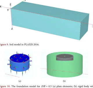
Figure 9 shows an specific view of the soil that modelled in PLAXIS sheet.
3.3.
Foundation
Model
The footing was modelled with two approaches. One approach is modelling by the plate elements. Plate elements can be used to model any necessary on-site excavations and foundations. It should be considered that the skirts thickness should be less than the footing’s one. The concrete properties applied to the plate elements. Other approach is that the foundation modelled as a rigid body
with interfaces which is more common in some cases (Figure 10).
3.4.
Meshes
Generating meshes is one of the most important parts of designing the footing. Plaxis allows us to perform meshes automatically. The 15-node wedge element is used which is composed of 6-node triangles in horizontal direction and 8-node quadrilaterals in vertical direction. The size of meshes is fine or very fine for ex-act results. The boundary conditions allowed no vertical or lateral soil
move-ment at the vertical boundaries. Figure 11 shows the finite element mesh for the
skirted foundation with D⁄B = 1 as an example.
3.5.
Loading
Condition
DOI: 10.4236/ojg.2018.86036 631 Open Journal of Geology
Figure 9. Soil model in PLAXIS 2016.
(a) (b)
Figure 10. The foundation model for D⁄B = 0.5 (a) plate elements; (b) rigid body with interfaces Meshes.
(a)
(b)
[image:9.595.229.519.251.357.2] [image:9.595.259.487.402.706.2]DOI: 10.4236/ojg.2018.86036 632 Open Journal of Geology
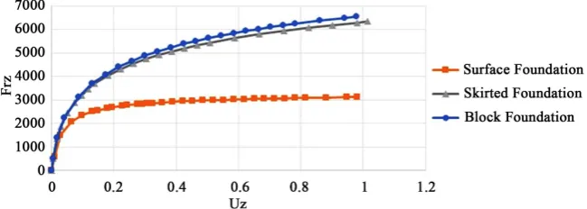
skirted foundation and a block foundation with embedment ratio of 0.5 were
analyzed with finite element method in uniform soil. Figure 12 shows the
nor-malized load-displacement curve for every three foundations. All foundations
had a vertical displacement, Uz into the soil. The breadth of both foundations
were 4 and they were modelled as rigid body.
In the chart, it can be seen that when the skirt penetrates, two times of its breadth, into the soil, the vertical capacity of the foundation increases to three
times compared with the surface foundation capacity. Figure 13 shows the
[image:10.595.210.535.384.500.2]fail-ure schematic view of the foundations after analyses, which has shown that, skirts help foundation to face a uniform settlement.
Figure 12. The normalized load-displacement curves for surface foundation and skirted foundation with D/B = 2.
(a) (b)
[image:10.595.269.481.546.691.2]DOI: 10.4236/ojg.2018.86036 633 Open Journal of Geology Figure 13 also shows that skirted foundation can approximately bring the bearing capacity of a block foundation together at the same circumstances and it can be observed that there difference is less than five percent. It means that soil block that confined between the skirts acts as a rigid body and help the
founda-tion to bear the pressures from the substructure(Eid (2012) [21]).
5.
Results:
Effect
of
Embedment
Ratio
on
the
Bearing
Capacity
of
Skirted
Foundations
(Uniform
Soil)
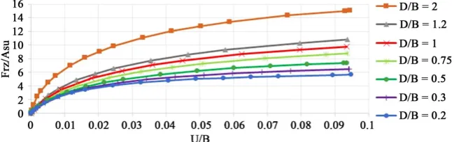
In order to investigate the effect of different length of skirts, the vertical bearing capacity of seven skirted foundations with seven different embedment ratios from 0.2 to 2 were analyzed with finite element method. In this section soil is uniform, which means that the undrained shear strength is constant in depth. Therefore, the foundation capacity, which was normalized by the area of the surface, A and the undrained shear strength, Su, increases until it reaches to a constant amount. That is the point where the ultimate load is reached. The
breadth B (Uz/B) normalized the displacements. In foundation model, the
foun-dation is modelled with two approaches, which applied in this section too.
[image:11.595.211.536.426.528.2]Fig-ure 14 and Figure 15 show the normalized vertical load-displacement curves for skirted foundations with seven different embedment ratios in uniform soil:
[image:11.595.213.535.578.692.2]Figure 14 and Figure 15 show the changes in bearing capacity with increasing the embedment ratio in uniform soil. It can be seen that the normalized bearing capacity will improve with increasing in the length of the skirt, however, the general trend and failure points are almost the same and identical. It
Figure 14. Normalized load-displacement curves for skirted foundation in uniform soil (plate elements).
DOI: 10.4236/ojg.2018.86036 634 Open Journal of Geology
drained shear strength will increase with depth with Equation (1) that have in-troduced in soil model. The method is that the undrained shear strength at the soil surface(Su,ref) would consider zero and a uniform increasing strength with
depth as typical of the soil conditions of a normally consolidated deposit. Skirted foundations with six different embedment ratios from 0.25 - 2 were analyzed by finite element method for this part investigation and the foundations are
mod-elled as rigid body. Figure 17 shows the normalized vertical load-displacement
curves for skirted foundations in normally consolidated soil:
(a)
[image:12.595.220.527.350.693.2](b)
DOI: 10.4236/ojg.2018.86036 635 Open Journal of Geology
Figure 17. Normalized load-displacement curves for skirted foundations in normally consolidated soil.
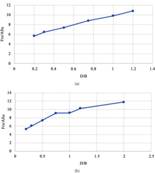
It can be seen in Figure 17 that the variation of normalized vertical bearing
capacity with increase in embedment ratio in normally consolidated soil is total-ly different with the one in uniform soil, however, the general trend is still iden-tical. The reason of this difference is that the way that the vertical bearing capac-ity is normalized, is different from normalization in uniform soil. Here the
ver-tical bearing capacity was normalized by the strength gradient with depth Su,ref
the area of the foundation A and the undrained shear strength at the skirt tip Su_0
which was calculated with the equation below:
0
, 1
u inc u
S B
S D B
×
= (3)
Therefore, as the amount of undrained shear strength at the skirt tip is differ-ent for any embedmdiffer-ent ratio and it will increase with the increase of the skirt’s length, the variation of normalized bearing capacity is different in normally
consolidated soil. Figure 17 also shows that there appears to be small differences
between the normalized bearing capacity of skirted foundations when the
em-bedment ratio is 0.5 - 2. Figure 18 will show this result in a better way:
7.
Results:
Bearing
Capacity
of
Skirted
Foundations
under
Combined
Vertical
and
Horizontal
Loading
(
v
-
h
)
As it was said before, bearing of a foundation under combined loading is more critical than the time it faced with gust absolute vertical or horizontal loading especially in offshore structures. Therefore, in this section, the horizontal load have been surcharged to the vertical load to evaluate the bearing capacity of the foundation in V-H space and reach the failure envelope. To do this, the dis-placement probe procedure have been employed. A skirted foundation with an embedment depth ratio of 0.5 have been modelled in PLAXIS 2016. The stages of modelling is just like the terms that have said before, the soil was uniform and the foundation has four meters width and has modelled as a rigid body with
rough interfaces with soil. a vertical displacement of Uz towards down and a
ho-rizontal displacement Ux to the right has been applied to the foundation on the
reference point. Four ratios of vertical displacement to horizontal one (Uz/Ux)
[image:13.595.213.535.72.185.2]DOI: 10.4236/ojg.2018.86036 636 Open Journal of Geology normally consolidated soil.
capacity have used to reach the failure envelope. The results were normalized with the ultimate vertical and horizontal bearing capacity. The results have
shown in Figure 19.
Figure 19 show that the failure envelope is similar to a curve with degree of 3, which leads us to an equation:
(
4.537)
3(
4.815)
2(
1.222)
1rx rz rz rz
rxult rzult rzult rzult
F F F F
F F F F
= − + + − +
(4)
This equation has r-square of 0.994 and tells us which combined loading in
V-H space can face the foundation with plastic deformations.
8.
Validation
of
Results
For validating the results of load-displacement curves, researches of Yun &
Bransby (2007) [22], have been used as a source. Yun & Bransby analyzed
skirted and embedded foundations with different embedment ratios in ABAQUS 6.2 [22]. Their way of modelling is just identical to the way that have used in this paper, however, in this paper two types of foundations have been applied but they modelled all foundations as rigid bodies. They also did a centrifuge test and an upper bound analysis to confirm their results. Their results have shown that the normalized vertical bearing capacity of a foundation with embedment ratio of 0.5 in uniform soil is 7.03. In this paper, such analysis with same conditions
concluded an amount of 7.38 for a skirted foundation with D/B = 0.5, which
means over 90 percent of conformity. Moreover, Yun & Bransby’s research in normally consolidated soil occasioned that the normalized vertical bearing ca-pacity for a skirted foundation with embedment ratio of 1 is 8.23 that when it is comprised with the result of this research in same condition, it would have
con-firmed a good matching with a percentage of more than 85 [20], The calibration
of the results of this study with some of the researches that have been conducted
by other researchers has shown in Figure 20 and Figure 21. These researches
are consist of analytical, numerical and experimental tests by famous researchers of this context such as: the upper bound analysis of Martin & Randolph (1999)
[image:14.595.215.537.74.200.2]DOI: 10.4236/ojg.2018.86036 637 Open Journal of Geology
[image:15.595.212.534.401.499.2]Figure 19. Failure envelope of a foundation with D/B = 0.5 in V-H space.
Figure 20.Verification of results of present study with previous researches (uniform soil).
Figure 21. Verification of results of present study with previous researches (normally consolidated soil).
& Bransby (2007) [22], and the finite element method analysis of Eslami &
Re-zazadeh (2017) [4].
These figures can confirm our results about the variation of the normalized bearing capacity by increase in embedment ratio in both uniform and normally consolidated soil.
For validating the results of finite element analysis on skirted foundations under combined loading of vertical and horizontal loading, the researches of Bienen et al. (2012), have been used. Their studies are on bearing capacity of
skirted foundations on uniform soil under combined loading [24]. Figure 22
shows the calibration of V-H failure envelope that they have presented with the
DOI: 10.4236/ojg.2018.86036 638 Open Journal of Geology
Figure 22. Calibration of the V-H failure envelope.
has shown that the schematic view of a failure envelope in V-H space is similar
to a curve or a quadrant (Yun (2007) [25]).
9.
Conclusions
Various types of semi-deep foundations have been introduced with their proper-ties and load conditions.
Several finite element analysis have been done on skirted foundations with various embedment ratios in uniform and normally consolidated soil and foun-dations with plate elements and rigid bodies by PLAXIS 2016. Moreover, a
skirted foundation with D/B = 0.5 in uniform soil has been analyzed under
com-bined loading of vertical and horizontal loading in V-H space and the failure
envelope has been presented.
Skirted foundations improve the bearing capacity of shallow foundations up to 3 times depend on their embedment ratio by penetrating to the depth of the soil. They also can supply the bearing capacity of an equivalent embedded foun-dation, which confirms that the trapped soil between the skirts can act as a rigid body and take part in bearing forces and pressures.
The effect of the length of skirt on the bearing capacity has been investigated by modelling and analyzing the skirted foundation in PLAXIS 2016 and the re-sults have been presented by normalized load-displacement curves. The curves have shown that in uniform soil, the normalized vertical bearing capacity would increase with increase in embedment ratio, however, in normally consolidated soil, the normalized vertical bearing capacity for the embedment ratios more than 0.5 is the same and it is because of the normalization and the changing in undrained shear strength with depth.
The verification of the results of various normalized vertical bearing capacity with increase in embedment ratio with other analytical, numerical and experi-mental researches showed a good conformity.
The bearing capacity of a skirted foundation under combined vertical and
ho-rizontal loading in V-H space has been analyzed by modelling a skirted
founda-tion with D/B = 0.5 in uniform soil for four different ratios of vertical
pre-DOI: 10.4236/ojg.2018.86036 639 Open Journal of Geology
sented, which shows a limited forces that the foundation can bear without any plastic deformations.
The V-H failure envelope has been validated by the research of Bienen et al.
(2012), and it has been observed that both have a same schematic view [24].
References
[1] Bransby, F. and Randolph, M. (1999) The Effect of Embedment Depth on the Un-drained Response of Skirted Foundations to Combined Loading. Soils and Founda-tions, 39, 19-33. https://doi.org/10.3208/sandf.39.4_19
[2] Bransby, M. and Yun, G.-J. (2009) The Undrained Capacity of Skirted Strip Foun-dations under Combined Loading. Géotechnique, 59, 115-125.
https://doi.org/10.1680/geot.2007.00098
[3] Mana, D., Gourvenec, S. and Randolph, M. (2010) A Numerical Study of the Ver-tical Bearing Capacity of Skirted Foundations. Proc. 2nd Int. Symp. Front. Off. Geotech. (ISFOG), Perth, 433-438.
[4] Rezazadeh, S. and Eslami, A. (2017) Bearing Capacity of Semi-Deep Skirted Foun-dations on Clay Using Stress Characteristics and Finite Element Analyses. Marine Georesources & Geotechnology, 1-15.
https://doi.org/10.1080/1064119X.2017.1361488
[5] Golder, H. (1976) The Canadian Manual on Foundation Engineering: Book Review.
Canadian Geotechnical Journal, 13, 499-504. https://doi.org/10.1139/t76-048
[6] Gupta, S.C. (2007) Raft Foundation Design and Analysis with a Practical Approach. New Age International.
[7] Saleh, N.M., Alsaied, A.E. and Elleboudy, A.M. (2008) Performance of Skirted Strip Footing Subjected to Eccentric Inclined Load. EJGE, 13, 1-33.
[8] Barari, A. and Ibsen, L.B. (2012) Undrained Response of Bucket Foundations to Moment Loading. Applied Ocean Research, 36, 12-21.
https://doi.org/10.1016/j.apor.2012.01.003
[9] Ibsen, L.B., Barari, A. and Larsen, K.A. (2015) Effect of Embedment on the Plastic Behavior of Bucket Foundations. Journal of Waterway, Port, Coastal, and Ocean Engineering, 141, 06015005.
https://doi.org/10.1061/(ASCE)WW.1943-5460.0000284
[10] Zhang, J., Chen, Z. and Li, F. (2010) Three Dimensional Limit Analysis of Suction Bucket Foundations. Ocean Engineering, 37, 790-799.
https://doi.org/10.1016/j.oceaneng.2010.02.017
[11] Hambly, E.C. (1985) Punch-Through Instability of Jack-Up On Seabed. Journal of Geotechnical Engineering, 111, 545-550.
https://doi.org/10.1061/(ASCE)0733-9410(1985)111:4(545)
[12] Mekbib, M. (2004) Performance of Piled Raft Foundations For Addis Ababa Soils. Addis Ababa University.
[13] Davis, E. and Poulos, H. (1972) The Analysis of Piled Raft Systems. Australia Geo-technique Journal, 2, 21-27.
[14] Eslami, M., Aminikhah, A. and Ahmadi, M. (2011) A Comparative Study on Pile Group and Piled Raft Foundations (PRF) Behavior Under Seismic Loading. Com-putational Methods in Civil Engineering Journal (CMCE), 2.
[15] Hemsley, J.A. (2000) Design Applications of Raft Foundations. Thomas Telford.
DOI: 10.4236/ojg.2018.86036 640 Open Journal of Geology [20] Al-Aghbari, M. and Mohamedzein, Y.-A. (2006) Improving the Performance of
Circular Foundations Using Structural Skirts. Proceedings of the Institution of Civil
Engineers-Ground Improvement, 10, 125-132.
https://doi.org/10.1680/grim.2006.10.3.125
[21] Eid, H.T. (2012) Bearing Capacity and Settlement of Skirted Shallow Foundations on Sand. International Journal of Geomechanics, 13, 645-652.
https://doi.org/10.1061/(ASCE)GM.1943-5622.0000237
[22] Yun, G. and Bransby, M. (2007) The Undrained Vertical Bearing Capacity of Skirted Foundations. Soils and Foundations, 47, 493-505.
https://doi.org/10.3208/sandf.47.493
[23] Hu, Y., Randolph, M. and Watson, P. (1999) Bearing Response of Skirted Founda-tion on Nonhomogeneous Soil. Journal of Geotechnical and Geoenvironmental En-gineering, 125, 924-935.
https://doi.org/10.1061/(ASCE)1090-0241(1999)125:11(924)
[24] Bienen, B., et al. (2012) Numerical Modelling of a Hybrid Skirted Foundation under Combined Loading. Computers and Geotechnics, 45, 127-139.
https://doi.org/10.1016/j.compgeo.2012.05.009
[25] Yun, G. and Bransby, M.F. (2007) The Horizontal-Moment Capacity of Embedded Foundations in Undrained Soil. Canadian Geotechnical Journal, 44, 409-424.

![Figure 4. Schematic of a Spudcan and Jack-up system in offshore industries (Hambly (1985) [11])](https://thumb-us.123doks.com/thumbv2/123dok_us/9285063.422876/5.595.277.466.73.275/figure-schematic-spudcan-jack-offshore-industries-hambly.webp)