SELF-ASSEMBLED MONOLAYERS ON SILICON:
DEPOSITION AND SURFACE CHEMISTRY
Małgorzata Adamkiewicz
A Thesis Submitted for the Degree of PhD at the
University of St Andrews
2013
Full metadata for this item is available in St Andrews Research Repository
at:
http://research-repository.st-andrews.ac.uk/
Please use this identifier to cite or link to this item: http://hdl.handle.net/10023/3938
This item is protected by original copyright
Self-Assembled Monolayers on Silicon –
Deposition and Surface Chemistry
School of Chemistry
Małgorzata Adamkiewicz
This thesis is submitted for the degree of
Doctor of Philosophy at the University of St Andrews
Supervisors: Dr Georg Hähner
1. Candidate’s declaration
I, Małgorzata Adamkiewicz, hereby certify that this thesis, which is approximately 32,000
words in length, has been written by me, that it is the record of my work carried out by me and that it has not been submitted in any previous application for a higher degree.
I was admitted as a research student in September 2009 and as candidate for the degree of PhD in September 2010, the higher study for which this is a record was carried out in the University of St Andres between 2009 and 2013.
Date: Signature of Candidate:
2. Supervisor’s declaration
I, hereby certify that the candidate has fulfilled the conditions of the Resolution and Regulations appropriate for the degree of Doctor of Philosophy in the University of St Andrews and that the candidate is qualified to submit this thesis in application for that degree.
3. Permission for electronic publication
In submitting this thesis to the University of St Andrews I understand that I am giving permission for it to be made available for use in accordance with the regulations of the University Library for the time being in force, subject to any copyright vested in the work not being affected thereby. I also understand that the title and the abstract will be published, and that a copy of the work may be made and supplied to anybona fidelibrary or research worker, that my thesis will be electronically accessible for personal or research use unless exempt by award of an embargo as requested below, and that the library has the right to migrate my thesis into new electronic forms as required to ensure continued access to the thesis. I have obtained any third-party copyright permissions that may be required in order to allow such access and migration, or have requested the appropriate embargo below.
The following is an agreed request by candidate and supervisor regarding the electronic publication of this thesis:
Embargo on both all of printed copy and electronic copy for the same fixed periods of two years on the following ground: publication would preclude future publication.
Date: Signature of Candidate:
Acknowledgements
First and foremost, I would like to thank my supervisor Dr Georg Hähner for his supervision, encouragement and advice during my PhD studies. I would like to thank Prof. David O’Hagan for co-supervision, all his help and support over the last three years and for giving me the opportunity to join his research group.
I would also like to thank Dr Tony O’Hara from MEMSStar and SPIRIT Studentship for funding this project.
I would particularly like to express my appreciation to Dr Neil Keddie and Dr Stephen Francis for all the helpful discussions and suggestions along the way, and for answering all my questions.
Thanks are also due to Dr Tomas Lebl and Mrs Melanja Smith for their assistance with solution NMR spectroscopy and Mrs Caroline Horsburgh for the mass spectroscopy. I would also like to acknowledge Prof. Peter Cumpson for the XPS analysis, Prof. Manfred Buck for allowing me to use an AFM microscope and Prof. Ifor Samuel for opportunity to use an ellipsometer. I am also grateful to Dr Zhe She and Dr Yue Wang for passing on their knowledge.
I would also like to thank all the members in the O’Hagan and Hähner group, both past and present, who I encountered during my studies. Thanks are also to Dr Michael Corr for his careful proof reading and Nouchali, Jason, Nawaf, Maciej and Yi for their friendship and support.
Abstract
Fabrication of surfaces with versatile functional groups is an important research area. Hence, it is essential to control and tune the surface properties in a reliable manner. Vinyl-terminated self-assembled monolayers (SAMs) offer significant flexibility for further chemical modification and can serve as a versatile starting point for tailoring of surface properties. Here a synthetic route for the preparation of vinyl-terminated trichlorosilane self-assembling molecules: 9-decenyltrichlorosilane (CH2=CH-(CH2)8-SiCl3), 10-undecenyltrichlorosilane (CH2=CH-(CH2)9-SiCl3), and 14-pentadecenyltrichlorosilane (CH2=CH-(CH2)13-SiCl3) is presented. These molecules were used for the preparation of SAMs in either liquid or vapour phase processes. Commercially available methyl-terminated self-assembling molecules: decyltrichlorosilane (CH3-(CH2)9-SiCl3) and octadecanetrichlorosilane (CH3-(CH2)17-SiCl3) were used as controls. The resultant films were characterised by X-ray photoelectron spectroscopy (XPS), contact angle analysis, ellipsometry, and atomic force microscopy (AFM).
Abbreviations
AFM - atomic force microscopy
AHTMS - (17-aminoheptadecyl)trimethoxysilane
AMP - ammonia/peroxide mixture
ASAP - atmospheric solids analysis probe mass spectrometry
ATR - attenuated total reflectance
BTEAC - benzyltriethylammonium chloride
CA - contact angle
CI - chemical ionisation
CM - cross metathesis
CuAAC - copper catalysed azide alkyne cycloaddition
DCM - dichloromethane
DI water - deionised water
DMF - dimethylformamide
EB - binding energy
EK - kinetic energy
ESCA - electron spectroscopy for chemical analysis
ESI - electrospray ionisation
Et2O - diethyl ether
EtOAc - ethyl acetate
FDTS - 1H,1H,2H,2H-perfluorodecyltrichlorosilane
HFAA - hexafluoroacetone azine
HFPO - hexafluoropropene oxide
HMP - hydrochloric/peroxide mixture
HO-TEMPO - 4-hydroxy-2,2,6,6-tetramethylpiperidine 1-oxyl
IR-CRDS - infrared cavity ring-down spectroscopy
λ - mean free path
MCPBA -meta-chloroperoxybenzoic acid
MDFA - methyl 2,2-difluoro-2-(fluorosulfonyl)-acetate
OTS - octadecanetrichlorosilane Piranha Solution - sulfuric acid/peroxide mixture
PMA - ethanolic solution of phosphomolybdic acid
PTC - phase transfer catalysis
RAIRS - reflection-absorption infrared spectroscopy
RMS - root mean square
rt - room temperature
SAM - self-assembled monolayer
SC-1 - standard clean 1
SC-2 - standard clean 2
SN2 - nucleophilic substitution
t-BuOK - potassiumtert-butoxide
TEMPO - 2,2,6,6-tetramethylpiperidine 1-oxyl
TFDA - trimethylsilyl 2,2-difluoro-2-(fluorosulfonyl)acetate
THF - tetrahydrofuran
TLC - thin layer chromatography
TML - trichloromethyllithium
TMSCF3 - trifluoromethyltrimethylsilane
TMSCl - trimethylsilyl chloride
Contents
1. Self-Assembled Monolayers and Their Chemical Modification by Surface Reactions...1
1.1. Self-Assembled Monolayers ...1
1.2. Deposition of SAMs ...3
1.3. Surface chemistry ...8
1.3.1. Nucleophilic substitution...8
1.3.2. Reactions involving double bonds ...10
1.3.3. Click chemistry ...13
1.3.4. Diels-Alder reactions... 14
1.3.5. Modification in the vapour phase...15
1.4. Aims of the project ...17
1.5. Literature ...18
2. Analytical Methods for Characterising Self-Assembled Monolayers ...22
2.1. X-ray Photoelectron Spectroscopy ...22
2.1.1. Details of XPS...24
2.2. Contact angle analysis ...24
2.2.1. Details of contact angle measurements ...26
2.3. Ellipsometry ...26
2.3.1. Details of ellipsometry ...27
2.4. Atomic Force Microscopy ...27
2.4.1. Details of AFM...29
2.5. Literature ...30
3. Synthesis of Vinyl-Terminated Self-Assembling Molecules ...31
3.1. Self-Assembling Molecules...31
3.1.1. The synthetic route of 9-decenyl- and 10-undecenyl- trichlorosilane...33
3.1.2. The synthetic route of 14-pentadecenyltrichlorosilane 1c ...35
3.2. Experimental...36
3.2.1. General Information ...36
3.2.2. Synthesis of self-assembling molecules ...38
3.2.2.1. Methyl 15-hydroxypentadecanoate - 3c19...38
3.2.2.2. Methyl 15-bromopentadecanoate - 4c20...38
3.2.2.3. tert-Butyl 14-pentadecanoate - 5c19...39
3.2.2.8. 11-Bromo-1-undecene - 5b20, 31, 32...42
3.2.2.9. 9-Decenyltrichlorosilane - 1a22...43
3.2.2.10. 10-Undecenyltrichlorosilane - 1b12, 22...43
3.3. Literature ...44
4. Deposition of Self-Assembled Monolayers...46
4.1. Surfactants ...47
4.2. Pre-treatment of the silicon substrates...48
4.2.1. Results and Discussion...49
4.2.1.1. X-ray Photoelectron Spectroscopy ...49
4.2.1.2. Contact angle ...50
4.2.1.3. Ellipsometry...51
4.2.2. Cleaning procedure ...52
4.3. Preparation of alkyl- and alkenyl- trichlorosilanes monolayers from the liquid phase. 52 4.3.1. Solution deposition process...53
4.3.2. Results and Discussion...54
4.3.2.1. Ellipsometry...54
4.3.2.2. X-ray Photoelectron Spectroscopy ...55
4.3.2.3. Contact angle ...58
4.3.2.4. Atomic Force Microscopy ...58
4.4. Preparation of alkyl- and alkenyl- trichlorosilanes monolayers in the vapour phase....59
4.4.1. Deposition process ...60
4.4.2. Results and Discussion...60
4.4.2.1. Ellipsometry...62
4.4.2.2. X-ray Photoelectron Spectroscopy ...63
4.4.2.3. Contact angle ...64
4.4.2.4. Atomic Force Microscopy ...65
4.5. Conclusions ...67
4.6. Literature ...69
5. Chemical Surface ModificationviaCarbene Chemistry in the Liquid Phase...71
5.1. Proof of concept ...71
5.2. Carbene precursors ...74
5.3. Chemistry on SAMs involving dichloro- and dibromo- carbene ...75
5.3.1. Chemistry and sources of :CCl2and :CBr2...76
5.3.2. Procedure for the reaction of CHCl3and CHBr3with SAMs ...79
5.3.3. Results and Discussion...79
5.3.3.1. X-ray Photoelectron Spectroscopy ...80
5.3.3.3. Ellipsometry...86
5.3.3.4. Atomic Force Microscopy ...87
5.3.4. Evidence forgem-dihalocyclopropane-terminated SAMs ...87
5.4. Chemistry on SAMs involving difluorocarbene...94
5.4.1. Chemistry and sources of :CF2...94
5.4.2. Procedure for the reaction of TMSCF3with SAMs ...97
5.4.3. Results and Discussion...97
5.4.3.1. X-ray Photoelectron Spectroscopy ...98
5.4.3.2. Water contact angle ...101
5.4.3.3. Ellipsometry...102
5.4.3.4. Atomic Force Microscopy ...103
5.4.4. Evidence forgem-difluorocyclopropane-terminated SAMs ...103
5.5. Conclusions ...107
5.6. Literature ...108
6. Chemical Surface Modification in the Vapour Phase ...110
6.1. Fluorinated Precursors ...110
6.2. Chemistry on SAMs involving hexafluoroacetone azine ...111
6.2.1. Chemistry of HFAA and sources ofbis(trifluoromethyl)carbene...111
6.2.2. Thermal stability of SAMs...115
6.2.3. Results and Discussion...116
6.2.3.1. Water Contact Angle ...117
6.2.3.2. Ellipsometry...117
6.2.4. Optimisation of the reaction conditions for SAMs modification...119
6.2.4.1. Procedure for the reaction of HFAA with SAMs ...119
6.2.4.2. Results and Discussion ...119
6.2.4.2.1. X-ray Photoelectron Spectroscopy...120
6.2.4.2.2. Water Contact Angle...128
6.2.4.2.3. Ellipsometry ...129
6.2.4.2.4. Atomic Force Microscopy...130
6.2.5. Evidence forbis(trifluoromethyl)cyclopropane-terminated SAMs ...131
6.3. Chemistry of SAMs exposed to hexafluoropropene oxide (HFPO)...135
6.3.1. Chemistry of HFPO...135
6.3.2. Optimisation of the reaction conditions ...136
6.3.2.3. Prolonged carbene generation with HFPO ...139
6.3.2.4. Control experiment with methyl- and vinyl- terminated SAMs and HFPO . 140 6.4. Conclusions ...141
6.5. Literature ...142
7. Summary...144
Appendix 1 - General experimental procedure for the reaction of CHCl3 and CHBr3 on SAMs ...146
Appendix 2 - Table A1 - SAMs modification with CHCl3and CHBr3...147
Appendix 3 - Synthesis of 1,1-dichloro-2-octylcyclopropane 5.10...148
Appendix 4 - Synthesis of 1,1-dibromo-2-octylcyclopropane 5.11 ...149
Appendix 5 - General experimental procedure for the reaction of TMSCF3 on SAMs ...149
Appendix 6 - Table A2 - SAMs modification with TMSCF3...150
Appendix 7 - Synthesis of 1,1-difluoro-2-octylcyclopropane 5.16 ...151
Appendix 8 - Table A3 - thermal degradation of SAMs ...152
Appendix 9 - Table A4 - vinyl-terminated SAMs modification with HFAA ...153
Appendix 10 - Table A5 - methyl-terminated SAMs modification with HFAA ...154
1. Self-Assembled Monolayers and Their
Chemical Modification by Surface Reactions
Surface science focuses on the investigation of physical and chemical phenomena that occur at interfaces, e.g. solid-gas, solid-liquid. By means of nanotechnology surface properties can be tuned for example by the formation and chemical modification of self-assembled monolayers (SAMs).1 SAMs are relatively easy to prepare and offer significant flexibility for introducing new chemical functionalities.2, 3 This feature makes self-assembly a versatile and unique modification method, which can be applied widely, for example in the design of biosensors.4, 5In this Chapter the current state of the art in liquid phase deposition as well as a review of surface reactions will be discussed.
1.1. Self-Assembled Monolayers
SAMs are ultrathin organic films formed by spontaneous adsorption of a surfactant onto a solid substrate.6, 7A schematic representation of a SAM is shown inFigure 1.1.
Figure 1.1.Schematic representation of a SAM.
applications in fields such as: protein adsorption,17-19 cell adhesion,20 bioactive surfaces,21 nanotechnology,22 biosensors,4, 5 chemical sensors,22, 23 protective coatings,24, 25 thin-film technology,25, 26microelectronics,27optoelectronics28, 29and others.30-32
Three different components can be distinguished in a self-assembling molecule used in SAM formation. These are a head group, a spacer, and a terminal functional group (Figure 1.2).
Figure 1.2.Construction of the self-assembling molecule.
The head group (reactive site) is a functionality with a strong affinity to a particular substrate.33 If silicon oxide is the substrate, head groups such as trichlorosilane (-SiCl3), trimethoxysilane (-Si(OCH3)3) or triethoxysilane (-Si(OCH2CH3)3) have been used, the first being the most reactive.7 When the reactive head group comes into contact with the substrate, a hydrolysis reaction of the Si-R (R = Cl, OCH3, OCH2CH3) bonds occur, involving water present on the oxide’s surface.3, 34 The silanes attachvia hydrogen bonds to the surface silanol groups and then a condensation reaction leads to covalent attachment and cross-linking between adjacent molecules (Scheme 1.1).3, 22, 35
O Cl
Si
Cl Cl Cl Si
Cl Cl H2O
O Si
H H
O O Si
H H
O O H
H
HO OH
-HCl -H2O
OH OH OH OH O OH O
Si O Si
O O
Silberzan et al.,3 also indicated that the silane molecules form a polymerised network, where molecules are linked to each other, with only a few anchoring bonds linking them to the surface. The presence of the cross-linked network of Si-O-Si bonds explains why wafers modified with alkylsiloxane monolayers exhibit roughness which is similar or lower than for unmodified substrates.22
The spacer is generally an alkyl chain36or an aromatic ring37(Figure 1.2). It plays a crucial role in the packing/ordering of the molecules on the surface.38 Longer alkyl chains (minimum 11 carbons)39result in the formation of closely-packed monolayers.2, 40
Finally, the terminal functional group (Figure 1.2) defines the properties of the surface. The chemical properties of a film can be tuned by introducing different terminal functional groups, either by deposition of self-assembling molecules with a modified end group, or by chemical transformation of the terminal group after the SAM film has been formed.41
1.2. Deposition of SAMs
SAMs can be prepared by immersion of a substrate into a solution of surface-active surfactant molecules (Scheme 1.2).
The mechanism of SAM formation is shown in Scheme 1.2. First, the self-assembling molecules chemisorb onto the surface with their reactive head groups -SiR3 (R = Cl, OCH3, OCH2CH3) facing the surface.42 The molecules organise via inter-molecular interactions between their spacers. SAM formation stops when the self-assembling molecules have reacted with all accessible reactive groups on the surface (Scheme 1.2). The thickness of a closely-packed and ordered SAM is determined by the length of the self-assembling molecule and the angle at which it is oriented relative to the surface.
The experimental modification of silicon substrates with SAMs via a silanisation reaction is relatively simple, but reproducing a well-defined monolayer is rather difficult due to the large number of parameters that influence the quality of the SAMs.3, 38, 43Thus, factors such as water content, type of surfactant, age and concentration of the solution, deposition time, temperature and the type of solvent must be carefully controlled.
The amount of water present in the surfactant solution or on the hydroxylated surface needs to be precisely controlled in order to obtain high-quality SAMs. In the absence of water, incomplete monolayers are formed.44, 45However, too much water causes excessive polymerisation of the trichlorosilanes in solution and results in deposition of polysiloxane on the surface rather than anchoring bonding.7, 13, 46-50
Self-assembling molecules, with different spacer lengths and types of reactive head group, also affect the overall SAM quality. Bierbaum et al.,51 reported that the ordering behaviour ofn-alkyltrichlorosilane films depends on the alkyl chain length. The optimum molecular length is eighteen carbons in order to obtain a monolayer with alkyl chains in all trans-conformation, oriented perpendicular to the surface. Moreover, short alkyl chain silanes with three51 or eight40, 52 carbons form disordered films. Long alkyl chain silanes with thirty51carbons form less ordered films.
Scheme 1.3. Possible products of the reaction of monochlorosilanes and dichlorosilanes with silicon dioxide surfaces (reprinted with permission from A. Y. Fadeev and T. J. McCarthy, Langmuir, 2000, 16, 7268-7274. Copyright © 2000, American Chemical Society).53
Trichlorosilanes are able to form densely-packed monolayers due to their ability to cross-polymerise. However, covalent attachments and vertical polymerisation are also possible (Scheme 1.4), thus the deposition parameters must be carefully controlled.53
2.5 × 10⁻¹M) caused formation of a less ordered film, which manifested itself by lower contact angle values (contact angle analysis, see Chapter 2). The authors concluded that at high concentrations too many molecules may deposit at the same time, thus their self-reorganisation might be difficult.58 Ito et al.,59 also investigated different solution concentrations in SAM formation. They found that at lower concentrations (<1 mM), incomplete monolayers were produced, while at higher concentrations (>5 mM), multilayers were formed.
Vallantet al.,60examined how the ‘age’ of the solution (i.e.time between solution preparation and immersion of the substrate) influenced monolayer formation. They tested SAM films prepared from a freshly made solution as well as from a solution stored for 2 h in a sealed vessel. The obtained results indicated that when an ‘old’ solution was used in the deposition process, large polymeric aggregates were present on the surface.61, 62
Influence of the deposition time63 on SAM formation was studied by Liu et al.64 They found that for adsorption times longer than 6 h, no changes in water contact angles were observed in the examinedn-alkylsilane SAMs.
Silberzanet al.,3observed that the deposition rate could be affected by temperature. An optimal quality of octadecanetrichlorosilane (OTS) monolayer was achieved in 2 min at 18 °C, while a 24 h reaction time did not lead to a satisfactory result at 30 °C. Brzoska34, 65 found that surface coverage was poor when deposition was performed at high temperature (~60 °C, 10 min). Moreover, the optimal deposition temperature T depends linearly on n-alkyl chain length and increases by 3.5 ± 0.5 °C for each additional CH2 group (Figure 1.3).
Parikh et al.,31 studied the effect of preparation temperature, in the range of 5-65 °C, on the structures of OTS monolayers on oxidised silicon substrates. They observed that the optimum deposition temperature of OTS films was 28 ± 0.5 °C. Above this temperature a gradual decrease of the film thicknesses was measured with increasing temperature. Moreover, Carraroet al.,66, 67 observed that SAM formation can be initiated by three different mechanisms at different temperatures; island growth at low temperatures
(T < 16 °C), homogenous growth at high temperatures (T ≥ 40 °C), and a mixed regime at
intermediate temperatures (Figure 1.4).58, 66
Figure 1.4. AFM images of partial SAMs grown at 10, 25 and 40 °C for 30 s (reprinted with permission from C. Carraro, O. W. Yauw, M. M. Sung and R. Maboudian, J. Phys. Chem. B, 1998,102, 4441-4445. Copyright © 1998, American Chemical Society).66
Rozlosnik et al.,68 investigated the effect of solvent polarity on the formation of OTS SAMs on silicon. They found that different solvents affect the water solubility and hence, SAM creation. Deposition of OTS from dodecane solutions resulted in multi-layered films. In contrast, the use of heptane as a solvent, caused the formation of high-quality monolayers. Cheng et al.,69 used four solvents: hexadecane, toluene, chloroform and dichloromethane for SAM preparations. Very smooth, monolayer films were obtained when either hexadecane or toluene were used in the deposition process. They also claimed that lower polarity solvents resulted in better molecular packing and smoother OTS films.
1.3. Surface chemistry
The properties of the surface of a substrate can be tuned by deposition of ultrathin films, formed from self-assembling molecules carrying different functionalities. A functional group can be introduced either before or after deposition. For example,
Bierbaum et al.,51 reported that amino silane films prepared from
(17-aminoheptadecyl)trimethoxysilane [AHTMS, NH2(CH2)17Si(OCH3)3] formed completely disordered SAMs. Otherwise, ordered and well-defined layers can be obtained by deposition of a molecule containing a terminal azide or cyanide group, followed by subsequent reduction to the corresponding amine.22, 70-72 The aim of this section is to present a selection of reactions used for surface modification such as nucleophilic substitution, reactions involving double bonds, click chemistry, Diels-Alder reactions as well as modifications in the vapour phase.
1.3.1. Nucleophilic substitution
Nucleophilic substitution reactions are an important class of reactions in organic and inorganic chemistry.73The replacement of a leaving group by a nucleophile takes place on a positively or partially positively charged atom. Nucleophiles are either negatively charged or neutral species with a free pair of electrons e.g.hydroxide, bromide, azide and cyanide ions, water, ammonia and others.73
Scheme 1.5. Schematic representation of nucleophilic substitution reactions on bromine-terminated monolayers and further modification towards -NH2and -SH moieties. (a) NaN3, DMF, rt, 24 h; (b) KSCN, DMF, rt, 20 h; (c) Na2S2, EtOH, reflux, 2 h; (d) Na2S DMF, 24 h; (e) LiAlH4, Et2O, rt, 24 h.70
Nucleophilic substitution reactions between halide-terminated SAMs and anionic nucleophiles (e.g. azide, thiocyanate, thiolate and iodine) were also studied by Fryxell75 and Koloski,76 while formation of a dense amine-functionalised SAM (via reduction of azide-terminated SAM) was investigated by Ofir77 and Heise,78due to its potential to graft polypeptides onto the substrate.5, 79, 80
In 1993, Lee and co-workers81 investigated the selective attachment of peptides onto halide-terminated surfaces. The reaction involved nucleophilic substitution of the halide by the thiol group from cysteine moieties of tri- and nona-peptides. The yields increased as follows:
RCl < RBr < RI
which is consistent with leaving group abilities in SN2 reactions.73 This methodology represented a powerful tool for the controlled attachment of peptides or proteins to solid substrates, a strategy used for biosensors and immunosensors.
1.3.2. Reactions involving double bonds
The first chemical reaction directly on SAMs was reported by Netzer and Sagiv.12 They performed hydroxylation of terminal vinyl groups by hydroboration/oxidation (BH3, H2O2) reactions. The products were then used for anchoring another monolayer. Preparation of a double layered SAM is not possible in a one-step procedure, due to the high reactivity of the trichlorosilane head groups towards the hydroxyl groups. Thus, reactions on pre-functionalised SAMs became a convenient method for multi-layered SAM formation on oxidised surfaces.2
In 1989, Wasserman et al.,13, 84 described simple reactions on vinyl-terminated monolayers resulting in hydroxyl-, carboxylic acid- and bromine-terminated films (Scheme 1.6, a, b and c). Recently, Song and co-workers85 performed an epoxidation reaction on double bonds of covalently grafted polynorbornene films on SiO2/Si substrates (Scheme 1.6, d). In both cases, the successful modification was confirmed by lower water contact angles of the modified films compared to the starting monolayers, while the thicknesses remained largely unchanged.
Scheme 1.6. The formation of -OH, -COOH and -Br terminated self-assembled monolayers, as well as epoxidation of polynorbornene films. (a) BH3 and H2O2,13 (b) KMnO4,13(c) 2% Br2in DCM,13(d) MCPBA.85
Maoz et al.,86 presented a microwave-induced formation of imide bilayers
octadecylamine through electrostatic/hydrogen-bonding interactions.87, 88 Exposure of a self-assembled amine-acid salt bilayer to microwaves resulted in the formation of an imide bilayer. The transformation induced by microwaves was a promising tool for the unusual surface modification and a novel route for the fabrication of new types of organised film structurese.g.biological membranes.
Scheme 1.7. Schematic representation of the microwave-induced conversion of a vinyl-terminated self-assembled monolayer into an imide bilayer.86
In 2000, Wang and co-workers89 demonstrated a convenient route to the covalent bonding of phosphorylocholine groups to solid substrates using vinyl-terminated SAMs. The resultant monolayers were biocompatible and prohibited the deposition of enzymes and proteins.
Siegenthaler et al.,90 published work on chemical surface modification via radical C-C bond-forming reactions. They performed a carboaminoxylation reaction
on alkene-terminated SAMs using HO-TEMPO-malonate
In 2003, Lee and co-workers91 studied the reactivity of undec-10-ene thiol SAMs (on gold) towards olefin cross-metathesis (CM). Olefin metathesis is an organic reaction in which two starting olefins in the presence of a catalyst form two new alkenes, due to the exchange of the double-bond carbons (Scheme 1.9).73
Scheme 1.9.Schematic of an olefin cross-metathesis.73
The successful conversion of vinyl-terminated SAMs intoα,β-unsaturated carbonyl groups was monitored by IR spectroscopy, X-ray photoelectron spectroscopy and contact angle analysis.
In 2006, Dutta et al.,92 reported functionalisation and patterning of olefin-terminated monolayers on a silicon substrate through cross metathesis. The reaction was performed on a mixed monolayer formed from di-olefin CH2=CH(CH2)9O(CH2)9CH=CH2 and 1-octadecene. The terminal vinyl groups were extended above the methyl groups in order to be easily accessible for the Grubbs catalyst and alkenes from the solution. Otherwise, the vinyl-terminated molecules might be too closely packed and thus the double bonds would not be accessible for interaction with the catalyst (Scheme 1.10, a). The olefins exposed on a monolayer could either react with each other (Scheme 1.10, b) or with alkenes from solution resulting in a functionalised monolayer (Scheme 1.10, c).
In order to obtain the highest conversion in cross metathesis (Scheme 1.10, c) the reaction conditions as well as the composition of the monolayer (1:1 ratio of di-olefin and 1-octadecene in solution, used in deposition process) must be strictly controlled.
The reported examples clearly indicate the potential of vinyl-terminated SAMs as starting films for further modification and introduction of new functionalities to solid substrates.
1.3.3. Click chemistry
Copper(I)-catalysed 1,3-dipolar cycloaddition of azides to terminal acetylenes is known as the ‘click’ reaction and it represents a versatile and useful method in organic chemistry.93, 94 The reaction has also found an application in the functionalisation of inorganic surfaces.38, 95 The introduction of 1,2,3-triazole moieties into the monolayer can be achieved in two ways. The first method uses acetylene terminated substrates for coupling with azide functionalised molecules,96, 97while the second method involves azide terminated substrates and terminal acetylene self-assembling molecules.98-100
An azide terminated monolayer can be obtained by nucleophilic substitution of -Br with -N3. Lummerstorfer and Hoffmann101 prepared 11-azido-undecylsiloxane monolayers
via substitution of a Br-terminated SAM. Subsequent coupling with various acetylenes yielded 1,2,3-triazoles (Scheme 1.11). Quantitative coupling was obtained when the reaction was performed at 70 °C for 24 h, without catalytic activation.
O Si O O N3 O Si O O N O Si O O Br a. b.
C11 C11 C11
N N R1
R2
R1= COOMe, R2= H
R1= R2= COOEt
HC≡C-Na.102
In the second method, either 1,8-nonadiyene97, 103 or 1,6-heptadiyene104 reacts with hydrogenated Si substrates. The use of 1,8-nonadyiene was reported by Ciampi and co-workers.103, 105 Their SAMs were further modified by CuAAC reactions in order to obtain 1,2,3-triazole monolayers (Scheme 1.12). The characterisation and reaction conversion was monitored by IR spectroscopy and optical reflectivity measurements, which revealed the presence of the desired functionalities. According to the authors103, 105 surface modification via ‘click’ reactions could be applied to produce functionalised surfaces in silicon-based sensing devices and implantable biomaterials.105
Scheme 1.12.Schematic representation of the 1,3-dipolar cycloaddition onto hydrogenated Si substrates. (a) The preparation of an alkyne-terminated monolayer from 1,8-nonadiyene, (b) R-N3cycloaddition with acetylene functionalised molecules.105
1.3.4. Diels-Alder reactions
101 ± 9° after cycloaddition with the hydrophobic dienophile (Scheme 1.13, b). Thermal cleavage of the hydrophobic dienophile resulted in regeneration of a hydrophilic state, CA 70 ± 6° (Scheme 1.13, c). This methodology is a convenient way of controlling surface properties by introducing various functionalities to a substrate. As a result, the wetting properties are modified.
Scheme 1.13. Preparation of Diels-Alder functionalised surface. (a) 2-Furoyl chloride, (b) fluorinated maleimide, THF, rt, 24 h, (c) toluene, reflux, 24 h.106
1.3.5. Modification in the vapour phase
Vapour phase chemical modifications are much more difficult to control than solution phase reactions and only a few examples have been published to date. Ozonolysis is one of the most studied gas-phase reactions, used to modify inorganic substrates coated with SAMs.107-109
In 2005, Fiegland et al.,108 studied the reaction of C=C terminated SAMs on gold exposed to gas-phase ozone. The authors found that reactions between ozone and vinyl-groups proceed through the formation of a -COOH moiety and its subsequent conversion into inter-chain carboxylic acid anhydride, which was revealed by Reflection-Absorption Infrared Spectra (RAIRS).
In 2008, Hallen and Hallen109developed a high yielding method for the production of carboxyl-terminated SAMs on silicon, by oxidising 10-undecenylsiloxane monolayers with gas-phase ozone, followed by hydrolysis in deionised water. The conversion of the reaction was monitored by contact angle analysis and ellipsometry measurements. Carboxyl-terminated SAMs exhibited a water contact angle of 16°, which decreased from ~100° for an unmodified film. Ellipsometry results showed the presence of a full monolayer after modification.
Apart from ozonolysis, a vapour phase modification of SAMsviaa free radical was also reported. In 1997, Baker and Walting110 investigated SAM functionalisation by free radical bromination reactions in both the liquid and vapour phases. The liquid phase reaction was performed using Br2/CCl4, while in the vapour phase process, SAMs were exposed to gaseous Br2in a sealed container. In both cases, wafers were irradiated for 6 h using a tungsten lamp, which resulted in brominated monolayers. SAM degradation was also observed in both cases, however, degradation in the vapour phase occurred much faster. Additionally, in comparison to 16-bromohexadecylsiloxane SAMs,74 monolayers produced by Baker and Walting110 were less organised, due to variable distribution of bromine across the alkyl chains (Scheme 1.14).
1.4. Aims of the project
The functionalisation of a surface containing a self-assembled monolayer is potentially very valuable as such a modification can alter surface properties. Alkylsiloxane SAMs are of particular interest, because they form chemically and physically stable films on various substrates.
Many different deposition methods have been investigated in order to reliably produce stable and ordered SAMs with a defined quality. In all the reported examples, liquid processes have been explored in detail. Although the preparation of SAMs on silicon substrates is relatively easy, reproducing well-defined monolayers is difficult due to various parameters that must be strictly controlled.3Thus, the first part of the thesis focuses on the development of a vapour phase deposition method of vinyl-terminated trichlorosilanes onto the silicon substrate. Vapour phase deposition can eliminate some disadvantages of liquid processes e.g. polymeric organosilane aggregates do not vaporise and, hence, do not deposit onto the surface. Moreover, this method can provide more homogenous coatings.54, 111
1.5. Literature
1. M. A. Van Hove,Catal. Today, 2006,113, 133-140.
2. N. Herzer, S. Hoeppener and U. S. Schubert,Chem. Commun., 2010,46, 5634-5652.
3. P. Silberzan, L. Leger, D. Ausserre and J. J. Benattar,Langmuir, 1991,7, 1647-1651.
4. N. K. Chaki and K. Vijayamohanan,Biosens. Bioelectron., 2002,17, 1-12. 5. D. Samanta and A. Sarkar,Chem. Soc. Rev., 2011,40, 2567-2592.
6. A. Ulman,An Introduction to Ultrathin Organic Films from Langmuir-Blodgett to Self-Assembly, Academic Press, San Diego, 1991.
7. A. Ulman,Chem. Rev., 1996,96, 1533-1554.
8. R. G. Nuzzo and D. L. Allara,J. Am. Chem. Soc., 1983,105, 4481-4483.
9. M. D. Porter, T. B. Bright, D. L. Allara and C. E. D. Chidsey,J. Am. Chem. Soc., 1987,109, 3559-3568.
10. S. E. Creager and G. K. Rowe,Anal. Chim. Acta, 1991,246, 233-239. 11. N. Bonnet, D. O'Hagan and G. Hahner,Chem. Commun., 2007, 5066-5068. 12. L. Netzer and J. Sagiv,J. Am. Chem. Soc., 1983,105, 674-676.
13. S. R. Wasserman, Y. T. Tao and G. M. Whitesides,Langmuir, 1989,5, 1074-1087. 14. R. Maoz and J. Sagiv,J. Colloid Interface Sci., 1984,100, 465-496.
15. J. Gun, R. Iscovici and J. Sagiv,J. Colloid Interface Sci., 1984,101, 201-213. 16. J. Gun and J. Sagiv,J. Colloid Interface Sci., 1986,112, 457-472.
17. S. Morgenthaler, C. Zink and N. D. Spencer,Soft Matter, 2008,4, 419-434. 18. J. Genzer, K. Efimenko and D. A. Fischer,Langmuir, 2006,22, 8532-8541. 19. C. Hoffmann and G. E. M. Tovar,J. Colloid Interface Sci., 2006,295, 427-435. 20. D. A. Stenger, J. H. Georger, C. S. Dulcey, J. J. Hickman, A. S. Rudolph, T. B.
Nielsen, S. M. McCort and J. M. Calvert,J. Am. Chem. Soc., 1992,114, 8435-8442.
21. C. S. Dulcey, J. H. Georger, V. Krauthamer, D. A. Stenger, T. L. Fare and J. M. Calvert,Science, 1991,252, 551-554.
22. S. Onclin, B. J. Ravoo and D. N. Reinhoudt,Angew. Chem., Int. Ed., 2005,44, 6282-6304.
23. S. Flink, F. van Veggel and D. N. Reinhoudt,Adv. Mater., 2000,12, 1315-1328. 24. T. O. Salami, Q. Yang, K. Chitre, S. Zarembo, J. Cho and S. R. J. Oliver,J.
Electron. Mater., 2005,34, 534-540.
25. K. L. Choy,Prog. Mater. Sci., 2003,48, 57-170.
26. J. D. Swalen, D. L. Allara, J. D. Andrade, E. A. Chandross, S. Garoff, J.
Israelachvili, T. J. McCarthy, R. Murray, R. F. Pease, J. F. Rabolt, K. J. Wynne and H. Yu,Langmuir, 1987,3, 932-950.
27. D. K. Aswal, S. Lenfant, D. Guerin, J. V. Yakhmi and D. Vuillaume,Anal. Chim. Acta, 2006,568, 84-108.
28. A. Ulman,Adv. Mater., 1990,2, 573-582.
29. B. Pignataro, A. Licciardello, S. Cataldo and G. Marletta,Mater. Sci. Eng. C, 2003,
23, 7-12.
30. E. Ruckenstein and Z. F. Li,Adv. Colloid Interface Sci., 2005,113, 43-63.
31. A. N. Parikh, D. L. Allara, I. B. Azouz and F. Rondelez,J. Phys. Chem., 1994,98, 7577-7590.
32. M. K. Chaudhury and G. M. Whitesides,Science, 1992,255, 1230-1232. 33. N. R. Glass, R. Tjeung, P. Chan, L. Y. Yeo and J. R. Friend,Biomicrofluidics,
34. J. B. Brzoska, N. Shahidzadeh and F. Rondelez,Nature, 1992,360, 719-721. 35. R. R. Rye, G. C. Nelson and M. T. Dugger,Langmuir, 1997,13, 2965-2972. 36. H. Brunner, T. Vallant, U. Mayer, H. Hoffmann, B. Basnar, M. Vallant and G.
Friedbacher,Langmuir, 1999,15, 1899-1901.
37. C. Combellas, F. Kanoufi, J. Pinson and F. I. Podvorica,J. Am. Chem. Soc., 2008,
130, 8576-8577.
38. J. J. Gooding and S. Ciampi,Chem. Soc. Rev., 2011,40, 2704-2718.
39. Y. Barness, O. Gershevitz, M. Sekar and C. N. Sukenik,Langmuir, 2000,16, 247-251.
40. Z. H. Jin, D. V. Vezenov, Y. W. Lee, J. E. Zull, C. N. Sukenik and R. F. Savinell, Langmuir, 1994,10, 2662-2671.
41. N. Herzer, C. Haensch, S. Hoeppener and U. S. Schubert,Langmuir, 2010,26, 8358-8365.
42. S. C. Tjong,Nanocrystalline Materials: Their Synthesis-Structure-Property-Relationships and Applications, Elsevier, Oxford, 2006.
43. R. Tian, O. Seitz, M. Li, W. Hu, Y. J. Chabal and J. Gao,Langmuir, 2010,26, 4563-4566.
44. J. D. Le Grange, J. L. Markham and C. R. Kurkjian,Langmuir, 1993,9, 1749-1753. 45. D. L. Angst and G. W. Simmons,Langmuir, 1991,7, 2236-2242.
46. M. E. McGovern, K. M. R. Kallury and M. Thompson,Langmuir, 1994,10, 3607-3614.
47. R. W. P. Fairbank and M. J. Wirth,J. Chromatogr. A, 1999,830, 285-291. 48. R. Wang and S. L. Wunder,Langmuir, 2000,16, 5008-5016.
49. T. Vallant, J. Kattner, H. Brunner, U. Mayer and H. Hoffmann,Langmuir, 1999,
15, 5339-5346.
50. D. H. Flinn, D. A. Guzonas and R. H. Yoon,Colloids Surf. A, 1994,87, 163-176. 51. K. Bierbaum, M. Kinzler, C. Woll, M. Grunze, G. Hahner, S. Heid and F.
Effenberger,Langmuir, 1995,11, 512-518.
52. T. Ohtake, N. Mino and K. Ogawa,Langmuir, 1992,8, 2081-2083. 53. A. Y. Fadeev and T. J. McCarthy,Langmuir, 2000,16, 7268-7274.
54. Y. X. Zhuang, O. Hansen, T. Knieling, C. Wang, P. Rombach, W. Lang, W. Benecke, M. Kehlenbeck and J. Koblitz,J. Microelectromech. Syst., 2007,16, 1451-1460.
55. J. Foisner, A. Glaser, J. Kattner, H. Hoffmann and G. Friedbacher,Langmuir, 2003,
19, 3741-3746.
56. J. T. Woodward and D. K. Schwartz,J. Am. Chem. Soc., 1996,118, 7861-7862. 57. C. J. Yu, A. G. Richter, J. Kmetko, S. W. Dugan, A. Datta and P. Dutta,Phys. Rev.
E, 2001,63, 021205.
58. S. Desbief, L. Patrone, D. Goguenheim, D. Guerin and D. Vuillaume,Phys. Chem. Chem. Phys., 2011,13, 2870-2879.
59. Y. Ito, A. A. Virkar, S. Mannsfeld, J. H. Oh, M. Toney, J. Locklin and Z. A. Bao,J. Am. Chem. Soc., 2009,131, 9396-9404.
60. T. Vallant, H. Brunner, U. Mayer, H. Hoffmann, T. Leitner, R. Resch and G. Friedbacher,J. Phys. Chem. B, 1998,102, 7190-7197.
64. Y. Liu, L. K. Wolf and M. C. Messmer,Langmuir, 2001,17, 4329-4335. 65. J. B. Brzoska, I. Benazouz and F. Rondelez,Langmuir, 1994,10, 4367-4373. 66. C. Carraro, O. W. Yauw, M. M. Sung and R. Maboudian,J. Phys. Chem. B, 1998,
102, 4441-4445.
67. M. M. Sung, C. Carraro, O. W. Yauw, Y. Kim and R. Maboudian,J. Phys. Chem. B, 2000,104, 1556-1559.
68. N. Rozlosnik, M. C. Gerstenberg and N. B. Larsen,Langmuir, 2003,19, 1182-1188.
69. Y.-a. Cheng, B. Zheng, P.-h. Chuang and S. Hsieh,Langmuir, 2010,26, 8256-8261.
70. N. Balachander and C. N. Sukenik,Langmuir, 1990,6, 1621-1627. 71. M.-T. Lee and G. S. Ferguson,Langmuir, 2001,17, 762-767.
72. S. Onclin, A. Mulder, J. Huskens, B. J. Ravoo and D. N. Reinhoudt,Langmuir, 2004,20, 5460-5466.
73. J. Clayden, N. Greeves and S. Warren,Organic Chemistry, 2 edn., Oxford University Press, Oxford New York, 2012.
74. N. Balachander and C. N. Sukenik,Tetrahedron Lett., 1988,29, 5593-5594. 75. G. E. Fryxell, P. C. Rieke, L. L. Wood, M. H. Engelhard, R. E. Williford, G. L.
Graff, A. A. Campbell, R. J. Wiacek, L. Lee and A. Halverson,Langmuir, 1996,
12, 5064-5075.
76. T. S. Koloski, C. S. Dulcey, Q. J. Haralson and J. M. Calvert,Langmuir, 1994,10, 3122-3133.
77. Y. Ofir, N. Zenou, I. Goykhman and S. Yitzchaik,J. Phys. Chem. B, 2006,110, 8002-8009.
78. A. Heise, M. Stamm, M. Rauscher, H. Duschner and H. Menzel,Thin Solid Films, 1998,327–329, 199-203.
79. O. Seitz, P. G. Fernandes, R. H. Tian, N. Karnik, H. C. Wen, H. Stiegler, R. A. Chapman, E. M. Vogel and Y. J. Chabal,J. Mater. Chem., 2011,21, 4384-4392. 80. A. Heise, H. Menzel, H. Yim, M. D. Foster, R. H. Wieringa, A. J. Schouten, V. Erb
and M. Stamm,Langmuir, 1997,13, 723-728.
81. Y. W. Lee, J. Reed-Mundell, J. E. Zull and C. N. Sukenik,Langmuir, 1993,9, 3009-3014.
82. Y. Wang, J. Cai, H. Rauscher, R. J. Behm and W. A. Goedel,Chem. Eur. J., 2005,
11, 3968-3978.
83. S. Sawoo, P. Dutta, A. Chakraborty, R. Mukhopadhyay, O. Bouloussa and A. Sarkar,Chem. Commun., 2008, 5957-5959.
84. S. R. Wasserman, G. M. Whitesides, I. M. Tidswell, B. M. Ocko, P. S. Pershan and J. D. Axe,J. Am. Chem. Soc., 1989,111, 5852-5861.
85. Z. Q. Song, X. F. Su, K. K. Huang, H. Lin, F. Q. Liu and J. Tang,Polymer, 2011,
52, 4456-4462.
86. R. Maoz, H. Cohen and J. Sagiv,Langmuir, 1998,14, 5988-5993.
87. R. Maoz, J. Sagiv, D. Degenhardt, H. Möhwald and P. Quint,Supramol. Science, 1995,2, 9-24.
88. R. Maoz, S. Matlis, E. DiMasi, B. M. Ocko and J. Sagiv,Nature, 1996,384, 150-153.
89. Y. L. Wang, T. J. Su, R. Green, Y. Q. Tang, D. Styrkas, T. N. Danks, R. Bolton and J. R. Liu,Chem. Commun., 2000, 587-588.
90. K. O. Siegenthaler, A. Schafer and A. Studer,J. Am. Chem. Soc., 2007,129, 5826-5827.
92. S. Dutta, M. Perring, S. Barrett, M. Mitchell, P. J. A. Kenis and N. B. Bowden, Langmuir, 2006,22, 2146-2155.
93. R. Huisgen,Angew. Chem., Int. Ed., 1963,2, 565-598.
94. H. C. Kolb, M. G. Finn and K. B. Sharpless,Angew. Chem., Int. Ed., 2001,40, 2004-2021.
95. S. Arumugam and V. V. Popik,J. Am. Chem. Soc., 2011,133, 15730-15736. 96. R.-V. Ostaci, D. Damiron, S. Capponi, G. Vignaud, L. Leger, Y. Grohens and E.
Drockenmuller,Langmuir, 2008,24, 2732-2739.
97. S. Ciampi, T. Böcking, K. A. Kilian, M. James, J. B. Harper and J. J. Gooding, Langmuir, 2007,23, 9320-9329.
98. A. G. Marrani, E. A. Dalchiele, R. Zanoni, F. Decker, F. Cattaruzza, D. Bonifazi and M. Prato,Electrochim. Acta, 2008,53, 3903-3909.
99. C. Gauchet, G. R. Labadie and C. D. Poulter,J. Am. Chem. Soc., 2006,128, 9274-9275.
100. T. Govindaraju, P. Jonkheijm, L. Gogolin, H. Schroeder, C. F. W. Becker, C. M. Niemeyer and H. Waldmann,Chem. Commun., 2008, 3723-3725.
101. T. Lummerstorfer and H. Hoffmann,J. Phys. Chem. B, 2004,108, 3963-3966. 102. R. D. Rohde, H. D. Agnew, W.-S. Yeo, R. C. Bailey and J. R. Heath,J. Am. Chem.
Soc., 2006,128, 9518-9525.
103. S. Ciampi, G. Le Saux, J. B. Harper and J. J. Gooding,Electroanalysis, 2008,20, 1513-1519.
104. L. Britcher, T. J. Barnes, H. J. Griesser and C. A. Prestidge,Langmuir, 2008,24, 7625-7627.
105. S. Ciampi, T. Böcking, K. A. Kilian, J. B. Harper and J. J. Gooding,Langmuir, 2008,24, 5888-5892.
106. P. T. Dirlam, G. A. Strange, J. A. Orlicki, E. D. Wetzel and P. J. Costanzo, Langmuir, 2009,26, 3942-3948.
107. Y. Dubowski, J. Vieceli, D. J. Tobias, A. Gomez, A. Lin, S. A. Nizkorodov, T. M. McIntire and B. J. Finlayson-Pitts,J. Phys. Chem. A, 2004,108, 10473-10485. 108. L. R. Fiegland, M. McCorn Saint Fleur and J. R. Morris,Langmuir, 2005,21,
2660-2661.
109. M. A. Hallen and H. D. Hallen,J. Phys. Chem. C, 2008,112, 2086-2090. 110. M. V. Baker and J. D. Watling,Langmuir, 1997,13, 2027-2032.
2. Analytical Methods for Characterising
Self-Assembled Monolayers
Many spectroscopic, microscopic and other characterisation techniques are employed in surface science to investigate various properties of nanostructures including self-assembled monolayers (SAMs). It is essential to have as much information as possible on the modified surfaces using a variety of analytical techniques.1 This Chapter describes the analytical techniques used in this study such as X-ray photoelectron spectroscopy (XPS), contact angle (CA) goniometry, ellipsometry, and atomic force microscopy (AFM).
2.1. X-ray Photoelectron Spectroscopy
X-ray photoelectron spectroscopy (XPS), also known as electron spectroscopy for chemical analysis (ESCA), is a powerful method for determining the elemental composition of materials’ surfaces.2 XPS measures the kinetic energy of core level electrons ejected from a material, after irradiation of a sample with monochromatic X-rays (Figure 2.1).
E
L
E
C
T
R
O
N
E
N
E
R
G
Y
Figure 2.1.Representation of a photoelectron emission process.3
EK=hv- EB Equation 2.1
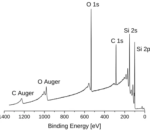
[image:36.595.184.427.215.426.2]Each element has a characteristic set of peaks in the spectrum and peaks’ positions are influenced by oxidation state of the element and its chemical environment. A typical XPS spectrum for a SiOx/Si substrate, coated with an organic film is shown inFigure 2.2.
Figure 2.2.The XPS spectrum of an organic coated SiOx/Si substrate.
The spectrum consists of narrow core-level photoelectron peaks (Si, C, O) and broad Auger peaks (C and O), while the background is formed by scattered electrons. The presence of peaks at particular EB indicates the presence of a specific element on the surface and the intensity of the peaks is related to the concentration of the element on the surface of the sample.
The X-rays may penetrate deep into the sample, however, the escape depth of the ejected electrons is limited.4The electrons ejected from depths greater than a few nm have a low probability to leave the surface without an energy loss, thus they contribute to the background signal, rather than appear as a well-defined peak.4 For this reason, XPS is a surface analytical technique used to determine the surface composition of a material only.
1400 1200 1000 800 600 400 200 0
O Auger C Auger
Si 2p Si 2s C 1s O 1s
2.1.1. Details of XPS
X-ray photoelectron spectroscopy analysis was performed either at the University of Newcastle (NEXUS at nanoLAB) or at the University of Edinburgh.
Newcastle X-ray photoelectron spectroscopy spectra were obtained using a
K-Alpha instrument (Thermo Scientific) and Al Kα radiation (1486.6 eV). During the
analysis, the pressure in the instrument chamber was kept around 3 × 10⁻⁸ mbar. The detector had a takeoff angle of 90° relative to the surface. Survey spectra were recorded with the analyser pass energy set to 200 eV. Single region scans were recorded with the pass energy of the analyser set to 20 eV.
Edinburgh X-ray photoelectron spectroscopy spectra were obtained using a VG
Sigma Probe (VG Scientific Ltd., UK) and Al Kα radiation (1486.6 eV). During the
analysis, the pressure in the instrument chamber was kept around 1.33 × 10⁻⁸ mbar. The detector had a takeoff angle of 37° relative to the surface. Survey spectra were recorded with the analyser pass energy set to 80 eV. The number of single region scans recorded for each element was typically 20, with the pass energy of the analyser set to 10 eV.
The XPS spectra were corrected for charging by referencing the aliphatic C 1s peak of hydrocarbons to 284.6 eV. Elemental compositions of the various surfaces were determined from the area under individual elemental peaks using sensitivity factors provided with the software as well as taking the transmission function of the analyser into account. CasaXPS (Casa Software Ltd., UK) was used for the analysis. The spectra were fitted using Gaussian/Lorentzian peak shapes with a ratio of 70%/30%. A Shirley background was subtracted for the quantitative analysis.
2.2. Contact angle analysis
Contact angle (θ) is the angle measured at the three-phase interface between air, a
Figure 2.3. Schematic representation of different levels of wettability of surfaces (redrawn).5
If the water contact angle is smaller than 90°, the surface of a solid is considered hydrophilic, while a water contact angle higher than 90° represents a hydrophobic surface. Superhydrophobic materials with very rough surfaces can exhibit a water contact angle of 150° or greater, due to the presence of air pockets under the liquid droplet (Figure 2.3).7 Also the presence of organic contaminants prevent wetting and result in higher contact angles.
The contact angle can be recorded either by placing a liquid droplet on the sample surface and measuring the angle (the static sessile drop method) or by measuring the angle by increasing and decreasing the liquid volume (the dynamic sessile drop method). The resulting contact angle obtained for the maximum liquid volume is referred to as the advancing angle, while the contact angle recorded for the minimum liquid volume is referred to as the receding angle (Figure 2.4). The difference between the advancing and receding angles (contact angle hysteresis) gives an indication of the smoothness and quality of the self-assembled monolayer.
Figure 2.4.Dynamic contact angle analysis which measures (a) advancing contact angleθa and (b) receding contact angleθ.
θ
θ
θ θ
θa θr
2.2.1. Details of contact angle measurements
Water contact angles (DI water) were measured with a G10 goniometer microscope (KRÜSS GmbH, Hamburg, Germany) under ambient conditions at room temperature. Droplets of ~3 µL were dispensed from a microburette. All reported values are the average of three measurements taken from different places of the surface. The error based on the observed variation of the contact angle of the organic films prepared under identical conditions was ± 1°.
2.3. Ellipsometry
Ellipsometry is a very sensitive, non-destructive technique widely used to characterise thin films.2The optical properties of thin films as well as film thicknesses can be calculated by measuring changes of an elliptically polarised light beam due to the interaction with the sample (Figure 2.5).8, 9
Figure 2.5.Schematic representation of an ellipsometry experiment.10
Ellipsometry measures the phase shift (Δ) and the amplitude component (Ψ) of the
reflected light. However, to obtain the parameters of interest (thickness and optical constants) it is necessary to build a model which represents the sample with its different
layers. Ψ and Δ are evaluated from the model giving a fit which is compared to the
Figure 2.6. Ellipsometry procedure to determine material properties from experimental data (redrawn).10
2.3.1. Details of ellipsometry
The thickness of the SAMs was measured with an M-2000DITM spectroscopic ellipsometer (J. A. Woollam Co., Inc., USA). Thickness values were extracted from fits to the data taken from 45 to 70° in steps of 5° over wavelengths from 200 to 1000 nm. The sample surface was modelled as a Si substrate with an oxide layer and a Cauchy layer.10 The thickness of the silicon oxide after the oxidative cleaning treatment was 16 ± 1 Å (average of three samples). The thickness of the monolayer films was calculated with a refractive index of 1.45.11, 12 The error based on the observed variation of the thickness of the organic films prepared under identical conditions was ~2 Å.
2.4. Atomic Force Microscopy
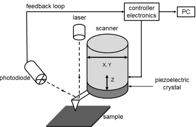
Figure 2.7. Schematic diagram of an atomic force microscopy and direct surface measurements – contact mode (based on a diagram in ref. 16).
The AFM can be operated in several modes for imaging such as a tapping mode, a non-contact mode and a contact mode - the latter was used in this study. In the contact mode, a tip and the surface of a sample remain in close contact as the scanning proceeds (‘contact’ means the repulsive regime of the intermolecular force curve, Figure 2.8). The cantilever deflection is maintained constant by the position adjustment of the scanner, thus the force between the tip and the sample is constant and a topographic image of the surface is produced.
force
distance
(tip-to-sample separation) contact
non-contact repulsive force
attractive force
Figure 2.8.Interatomic force versus distance curve.
In the non-contact region, the cantilever is held on the order of tens to hundreds of angstroms from the sample surface, and the interatomic force between the cantilever and the sample is attractive. In the contact region, the cantilever is held less than a few angstroms from the sample surface, and the interatomic force between the cantilever and the sample is repulsive.17
2.4.1. Details of AFM
2.5. Literature
1. D. Samanta and A. Sarkar,Chem. Soc. Rev., 2011,40, 2567-2592. 2. C. R. Brundle, J. C. A. Evans and S. Wilson,Encyclopedia of Materials
Characterization, Manning Publications Co., Greenwich, 1992.
3. J. F. Watts and J. Wolstenholme,An Introduction to Surface Analysis by XPS and AES, John Wiley & Sons Ltd, Chichester, West Sussex, 2003.
4. N. Fairley,CasaXPS Manual 2.3.15 XPS AES ToF-MS SNMS Dynamic-SIMS, Casa Software Ltd., Devon, 2009.
5. R. Forch, H. Schonherr and A. T. A. Jenkins,Surface Design: Applications in
Bioscience and Nanotechnology, Wiley-VCH, Weinheim, 2009.
6. A. Ulman,An Introduction to Ultrathin Organic Films from Langmuir-Blodgett to Self-Assembly, Academic Press, San Diego, 1991.
7. S. Wang and L. Jiang,Adv. Mater., 2007,19, 3423-3424.
8. R. M. A. Azzam and N. M. Bashara,Ellipsometry and Polarized Light, North-Holland Publishing Co., Amsterdam, 1977.
9. H. G. Tompkins and E. A. Irene,Handbook of ellipsometry, William Andrew Publishing, Norwich, 2005.
10. C. Herzinger and B. Joghs,Guide to Using WVASE 32, J. A. Woollam Co., Inc., 1996.
11. N. Tillman, A. Ulman, J. S. Schildkraut and T. L. Penner,J. Am. Chem. Soc., 1988,
110, 6136-6144.
12. D. L. Angst and G. W. Simmons,Langmuir, 1991,7, 2236-2242.
13. G. Binnig, C. F. Quate and C. Gerber,Phys. Rev. Lett., 1986,56, 930-933. 14. C. J. Chen,Introduction to Scanning Tunneling Microscopy, Oxford University
Press, Inc., New York, 1993.
15. F. J. Giessibl,Rev. Mod. Phys., 2003,75, 949-983.
16. Scanning Probe Microscopy Training Notebook (Version 3.0), Digital Instruments,
Veeco Metrology Group, 2000.
3. Synthesis of Vinyl-Terminated
Self-Assembling Molecules
Long chain alkyl organosilane compounds are widely used to modify the properties of inorganic material surfaces. They can form very stable films, thus are commonly used in semiconductor technology, for example in micro-electromechanical systems (MEMS) and nano-electromechanical systems (NEMS).1-5 Silane-based precursor molecules can contain one (R3SiX), two (R2SiX2) or three (RSiX3) good leaving groups. Although all three silanes are used in the modification of hydroxylated surfaces, only trifunctional ones are able to form closely packed monolayers, because of their ability to form cross-linking bonds between two adjacent head groups,6 as discussed in Chapter 1. SAMs formed from mono- and di-functional self-assembling molecules are less dense due to steric repulsion between the ‘R’ groups of adjacent silane head groups.7-9 Precursor molecules with three reactive sites are usually functionalised with either halogen or alkoxy groups (Si-X3where X = Cl, (OCH3)3 or (OCH2CH3)3), and chlorosilanes are preferred over alkoxysilanes as they are more reactive.9, 10 However, the high reactivity and the water sensitivity of the chlorosilane head group limits the range of terminal functional groups that can be introduced onto the silane precursors.11 If the terminal functional group reacts with the trichlorosilane group, this leads to the formation of polymeric aggregates in solution, which subsequently react with the surface, resulting in an inhomogeneous films.
3.1. Self-Assembling Molecules
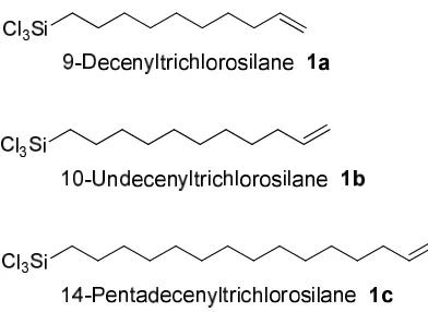
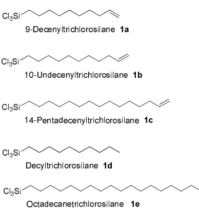
In this project a series of vinyl-terminated SAMs were required. The target molecules were vinyl-terminated trichlorosilanes with alkyl chain lengths of ten (9-decenyltrichlorosilane 1a (CH2=CH-(CH2)8-SiCl3)), eleven (10-undecenyltrichlorosilane
Figure 3.1.Synthetic targets for the formation of SAMs on silicon substrates. Two different synthetic approaches for preparing the trichlorosilane precursors
1a-1c are described in the literature.12-18 The routes are summarised in Scheme 3.1 and
Scheme 3.2.
Scheme 3.1.First synthetic route to obtain trichlorosilane self-assembling molecules.12, 13 Wasserman et al.,12 prepared long chain alkyl trichlorosilanes via a Grignard reaction using a bromide precursor following the procedure described by Whitmoreet al.,13 as illustrated in Scheme 3.1. In a similar manner, Maoz and Sagiv synthesised trans -13-docosentyltrichlorosilane (CH3(CH2)7CH=CH(CH2)12SiCl3) by transforming the alcohol into the bromide derivative, which was then converted into the trichlorosilanevia addition of its Grignard reagent and excess of tetrachlorosilane.14, 15 According to the literature the synthesis of trichlorosilanes have yields of ~50%. In the second method, trichlorosilane (HSiCl3) was reacted with a vinyl-terminated alkene in the presence of a platinum catalyst12, 16, 17 as shown in Scheme 3.2. The yield of this reaction was reported to be around 70%.
3.1.1. The synthetic route of 9-decenyl- and 10-undecenyl- trichlorosilane
The synthetic route developed for the preparation of 9-decenyltrichlorosilane (1a) and 10-undecenyltrichlorosilane (1b) is illustrated inScheme 3.3.
Scheme 3.3.Synthesis of 9-decenyl- and 10-undecenyl- trichlorosilane.
In the first step, commercially available 9-decen-1-ol (4a) and 10-undecen-1-ol (4b), were treated with carbon tetrabromide and triphenylphosphine in dichloromethane, as precursors to the bromides 5a and 5b. The reaction proceeded quickly and the starting material was consumed in less than three hours. The compounds5a and 5b were purified by distillation under reduced pressure and obtained in good yields of 92% and 77%, respectively. The resultant trichlorosilanes1aand1bwere then obtained by the reaction of tetrachlorosilane (SiCl4) with the Grignard reagents prepared from5aand5b. The products
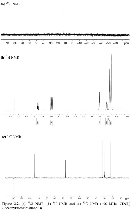
(b)1H NMR
Figure 3.2. (a) 29Si NMR, (b) 1H NMR and (c) 13C NMR (400 MHz, CDCl3) of 9-decenyltrichlorosilane1a.
(a)29Si NMR
3.1.2. The synthetic route of 14-pentadecenyltrichlorosilane 1c
The synthetic route used for the preparation of the longest chain precursor 1c is illustrated inScheme 3.4.
Scheme 3.4.Synthetic route of 14-pentadecenyltrichlorosilane1c.
In the first step of the reaction sequence, commercially available
ω-pentadecalactone 2c was used as a starting material. Following a procedure described by Hostetler et al,19 nucleophilic ring opening of lactone2c with sodium methoxide afforded
ω-hydroxy methyl ester 3c. The product was then purified by column chromatography and
isolated in very good yield (96%). Conversion of the ω-hydroxy methyl ester 3c to
ω-bromo ester4cwas achieved as before by an Appel reaction using triphenylphosphine and carbon tetrabromide in dichloromethane.20 Purification of compound 4c was easily
achieved by chromatography and obtained also in a good yield (90%). The ω-bromo
methyl ester 4c was then treated with an excess of t-BuOK resulting in two reactions occurring simultaneously at both ends of the molecule. First, HBr elimination provided the expected terminal alkene, but also a transesterification of the methyl ester into the corresponding tert-butyl ester occurred. Purification of the ω-unsaturated tert-butyl ester
5c was achieved by column chromatography and this product could be isolated in 82% yield.19 Reduction of ester 5c with lithium aluminium hydride (LiAlH4) resulted in its
reagent and was reacted with tetrachlorosilane.22 Both the reaction and work-up had to be performed under an inert atmosphere (nitrogen) using oven-dried glassware. 14-Pentadecenyltrichlorosilane (1c) was isolated by Kugelrohr distillation with moderate yield of 39%. The trichlorosilane products are very moisture sensitive, and must be stored in an inert atmosphere in a cool, dark place.
3.2. Experimental
3.2.1. General Information
Materials. Chemicals were obtained from commercial sources (Sigma-Aldrich,
Alfa Aesar, Acros, and Fisher Scientific) and were used as received. All reactions were performed under an inert atmosphere using oven-dried glassware.
Commercially available n-type, one-side polished silicon (100) wafers (Wacker, Munich, Germany) were used as substrates.
Instrumentation. 1H NMR spectra were recorded on Bruker Avance 300 (300
MHz); Bruker Avance II 400 (400 MHz). All spectra were acquired in deuterochloroform. The multiplicity of each signal is indicated by: s (singlet); bs (broad singlet); d (doublet); t (triplet); dd (doublet of doublets); dddd (doublet of doublet of doublet of doublets); q (quartet); m (multiplet). The number of protons (n) for a given resonance signal is indicated by nH. Coupling constants (J) are quoted in Hz and are recorded to the nearest 0.1 Hz. Identical proton coupling constants are averaged in each spectrum and reported to the nearest 0.1 Hz. The coupling constants were determined by analysis using Bruker TopSpin software.
13
C NMR spectra were recorded on a Bruker Avance 300 (75 MHz) or on a Bruker Avance II 400 (101 MHz) spectrometer.
29
19
F NMR spectra were recorded on a Bruker Avance 300 (282 MHz) or on a Bruker Avance II 400 (376 MHz). The chemical shift data for each signal are given asδin units of parts per million (ppm). Coupling constants (J) are quoted in Hz and are recorded to the nearest 0.1 Hz.
Mass spectrometry spectra were obtained on Waters Micromass GCT Time of Flight Mass Spectrometer using electron impact or chemical ionisation techniques. Chemical ionisation spectra were obtained using methane as the ionising gas. Electrospray ionisation spectra were obtained on Waters Micromass LCT Time of Flight Mass Spectrometer coupled to a Waters 2975 HPLC, operating in positive or negative mode, from solutions of acetonitrile; m/z values are reported in Daltons. Samples sent to the EPSRC mass spectrometry service in Swansea were analysed on a Thermofisher LTQ Orbitrap XL mass spectrometer using either atmospheric pressure chemical ionisation (APCI) or electrospray ionisation (ESI).
Melting points were measured using an Electrothermal 9100 or Gallenkamp Griffin MPA350 melting point apparatus, and are uncorrected.
Analytical thin layer chromatography (TLC) was carried out on Merck silica gel 60 F254aluminium-supported thin layer chromatography sheets. Visualisation was by thermal development after dipping in an ethanolic solution of phosphomolybdic acid (PMA).
Flash Column chromatography was carried out on Merck Geduran silica gel 60 (400-630 mesh), eluting with solvents as supplied under a positive pressure of compressed air.
Anhydrous solvents (diethyl ether, hexane, dichloromethane, tetrahydrofuran) were obtained using a MBRAUN GmbH MB SPS-800 solvent purification system.
3.2.2. Synthesis of self-assembling molecules
3.2.2.1. Methyl 15-hydroxypentadecanoate - 3c19
MeO OH
O 1
2 3
4 5
6 7
8 9
10 11
12 13
14 15
Sodium methoxide was generated by the addition of sodium metal (2.4 g, 104 mmol, 5.0 eq) to dry MeOH (130 mL) at 0 °C. The mixture was warmed to rt and
stirred until all of the sodium was consumed. ω-Pentadecalactone 2c (5.0 g, 21 mmol, 1.0 eq) was added in a single portion and the solution was warmed to 80 °C and stirred for 3 h. The reaction was cooled to rt and quenched with HCl solution (1 M, 175 mL) and diluted with water (175 mL). The aqueous layer was extracted into diethyl ether (3 × 100 mL), and the combined organic layers were washed with water (150 mL), brine (150 mL), and dried over MgSO4 and the solvent removed in vacuo. The product was purified by silica gel chromatography (2:1 hexane:EtOAc), to afford methyl 15-hydroxypentadecanoate3c(5.43 g, 96%) as a colourless solid: mp 46-48 °C [Lit.19 47-48 °C]; 1H NMR (400 MHz, CDCl3) δH 3.65 (3H, s, OCH3), 3.63 (2H, t, J 6.6 Hz, CH2OH), 2.29 (2H, t, J7.0 Hz, CH2COOCH3), 1.62-1.54 (4H, m, CH2CH2OH and CH2CH2COOCH3), 1.31-1.23 (20H, m, CH2: C4-C13); 13C NMR (101 MHz, CDCl3) δC 174.4 (C=O), 63.2 (CH2OH), 51.5 (OCH3), 34.2 (CH2COOCH3), 32.8, 29.6, 29.5, 29.4, 29.2, 29.1, 25.7, 24.9 (CH2: C3-C14);m/z(ESI): C16H31NaO3[M+Na]+294.97.
3.2.2.2. Methyl 15-bromopentadecanoate - 4c20
to a brown oil, hexane (200 mL) was added and the mixture was stirred for 15 min. The resulting white precipitate was removed by filtration, and the filtrate was concentrated in vacuo. The product was purified over silica gel (20:1 hexane:EtOAc), to afford methyl 15-bromopentadecanoate 4c (4.6 g, 90%) as a colourless solid: mp 38-40 °C [Lit.19 38-39 °C];1H NMR (400 MHz, CDCl3)δH3.65 (3H, s, OCH3), 3.39 (2H, t,J6.9 Hz, CH2Br), 2.29 (2H, t, J 7.5 Hz, CH2COOCH3), 1.87-1.80 (2H, m, CH2CH2Br), 1.64-1.56 (2H, m, CH2CH2COOCH3), 1.44-1.36 (2H, m, CH2CH2CH2Br), 1.31-1.21 (18H, m, CH2: C4-C12); 13
C NMR (101 MHz, CDCl3)δC51.6 (OCH3), 34.2, 33.0, 29.9, 29.7, 29.6, 29.5, 29.4, 29.3, 28.9, 28.3, 25.1 (CH2: C2-C15); HRMS m/z (CI): calculated for C16H32O279Br1 [M+H]+ 335.1586, found 335.1595.
3.2.2.3. tert-Butyl 14-pentadecanoate - 5c19
Methyl 15-bromopentadecanoate 4c (4.0 g, 11.9 mmol, 1.0 eq) was added to a solution oftBuOK in THF (1 M, 60 mL) and the reaction mixture was stirred at rt for 1 h. The reaction was then quenched with HCl solution (1 M, 150 mL). The aqueous layer was extracted into diethyl ether (3 × 100 mL), and the combined organic layers were washed with water (150 mL), brine (150 mL), dried over MgSO4 and the solvent was removed in
vacuo. The product was purified over silica gel (100:1 hexane:EtOAc), to afford tert-butyl 14-pentadecanoate 5c (2.89 g, 82%) as a colourless oil; 1H NMR (300 MHz, CDCl3) δH 5.80 (1H, dddd,J 17.2, 10.2, 6.8, 6.8 Hz, CH=CH2), 4.96 (1H, dddd, J17.2, 3.5, 1.5, 1.5 Hz, CH=CH215b), 4.90 (1H, dddd, J 10.2, 3.5, 1.5, 1.5 Hz, CH=CH215a), 2.19 (2H, t,
J7.4 Hz, CH2COOC(CH3)3), 2.07-1.99 (2H, m, CH2CH=CH2), 1.61-1.51 (2H, m, CH2CH2COOC(CH3)3), 1.44 (9H, s, OC(CH3)3), 1.31-1.22 (18H, bs, CH2: C4-C12); 13