warwick.ac.uk/lib-publications
A Thesis Submitted for the Degree of PhD at the University of Warwick
Permanent WRAP URL:
http://wrap.warwick.ac.uk/91038
Copyright and reuse:
This thesis is made available online and is protected by original copyright. Please scroll down to view the document itself.
Please refer to the repository record for this item for information to help you to cite it. Our policy information is available from the repository home page.
Device-to-Device Communication in
Cellular Networks: Multi-Hop Path
Selection and Performance
by
Hu Yuan
Thesis
Submitted to the University of Warwick in partial
fulfilment of the requirements for the degree of
Doctor of Philosophy
School of Engineering
Contents
List of Tables vi
List of Figures vii
Acknowledgments xi
Declarations xii
List of Publications xiii
Abbreviations xiv
Abstract xix
Chapter 1 Introduction 1
1.1 Background . . . 1
1.2 D2D in 3GPP Standardization . . . 4
1.2.1 Architecture Enhancements to Support D2D . . . 5
1.2.2 D2D Communication Scenarios . . . 5
1.3 The Application Areas of D2D . . . 6
1.3.1 Commercial services . . . 7
1.3.2 Public safety applications . . . 7
1.4 Research Contributions . . . 8
1.5 Thesis Outline . . . 11
Chapter 2 Review of Device-to-Device Communication 13 2.1 Overview of Communication Performance Benefits . . . 13
2.2.1 Inband D2D . . . 16
2.2.2 Outband D2D Communication . . . 20
2.3 Review of Multi-hop Routing Algorithms . . . 23
2.3.1 Broadcasting Wireless Routing . . . 23
2.3.2 Geographical Wireless Multi-hop Routing . . . 26
2.3.3 FlashLinQ Routing Algorithm . . . 31
2.3.4 BS Assistance for D2D Communications Routing . . . 33
2.4 Interference Aware Multi-hop . . . 37
2.4.1 Exclusion Zone Strategy . . . 37
2.5 Conclusions . . . 39
Chapter 3 Methodologies for Wireless Network Modelling 40 3.1 Introduction . . . 40
3.2 Monte Carlo Simulation . . . 41
3.2.1 Statistical Pathloss Model . . . 43
3.2.2 Ray Tracing by Wireless InSite . . . 44
3.3 Stochastic Geometry . . . 45
3.3.1 Spatial Point Process . . . 46
3.3.2 Distance to the Nearest BS . . . 50
3.3.3 Signal-to-Interference-plus-Noise Ratio Model . . . 51
3.3.4 Network Capacity . . . 55
3.4 Conclusion . . . 57
Chapter 4 Emergency D2D Route Selection in an Urban Envi-ronment 58 4.1 Introduction . . . 58
4.2 Experiment Setup . . . 60
4.2.1 Cellular Network . . . 60
4.2.2 Urban Propagation Model . . . 60
4.3 Outage Probability Definition . . . 64
4.3.1 CC Outage Probability . . . 64
4.3.2 D2D Outage Probability . . . 64
4.4 D2D Routing Strategies . . . 65
4.4.1 Restricted Broadcast-Routing (RBR) Algorithm . . . . 65
4.4.3 Interference Aware Routing (IAR) Algorithm . . . 67
4.5 Results and Analysis . . . 69
4.5.1 D2D Routing Distance . . . 70
4.5.2 D2D User Density . . . 71
4.5.3 Wall Penetration Loss . . . 72
4.5.4 CC Performance Constraint with D2D . . . 73
4.6 Conclusions . . . 75
Chapter 5 Multi-Hop Path Selection in a Cellular Interference Environment 76 5.1 Introduction . . . 76
5.2 System Setup . . . 77
5.2.1 Spectrum Allocation . . . 77
5.2.2 D2D UEs Distribution . . . 77
5.3 Routing Strategies . . . 78
5.4 Success Probability of D2D Multi-hop Communication . . . . 79
5.4.1 Average Hop Distance . . . 81
5.4.2 Success Probability for Single Hop D2D . . . 83
5.4.3 Success Probability for multi-hop SPR Scheme . . . 85
5.4.4 Success Probability for IAR Scheme . . . 88
5.5 Results and Analysis . . . 92
5.5.1 Number of Hops . . . 93
5.5.2 Network Capacity . . . 94
5.5.3 Communication Success Probability . . . 96
5.5.4 Operational Zones and Offloaded Traffic Volume . . . . 97
5.6 Conclusions . . . 100
Chapter 6 Collision Probability and Routing Strategy with Lim-ited Location Information 102 6.1 Introduction . . . 102
6.2 System model . . . 104
6.2.1 D2D Routing Scenarios . . . 104
6.2.2 Collision Area (CA) . . . 106
6.3 Collision Probability . . . 107
6.3.2 Intra-cell to Cell Boundary Routing Path . . . 110
6.3.3 Cell Boundary to Boundary Routing Path . . . 110
6.4 Results and Analysis . . . 111
6.4.1 Single-Cell and Multi-Cell Results . . . 111
6.4.2 Gradient Based Switch Strategy . . . 114
6.5 Conclusion . . . 116
Chapter 7 D2D in LTE-Unlicensed Heterogeneous Network 117 7.1 Introduction . . . 117
7.2 System Model . . . 118
7.2.1 UEs Distribution . . . 119
7.2.2 Wi-Fi Channel Capacity . . . 119
7.3 The D2D Routing Algorithm with LBT . . . 122
7.3.1 Listen Before Talk (LBT) . . . 122
7.3.2 SPR Routing Algorithm with LBT . . . 123
7.4 Traffic Model for D2D UEs with LBT . . . 123
7.4.1 D2D UEs Waiting Probability . . . 124
7.4.2 Average Time Delay for D2D UEs . . . 126
7.5 Results and Analysis . . . 127
7.5.1 Waiting Probability for D2D UEs with LBT . . . 127
7.5.2 Delay time for the D2D UEs with LBT . . . 128
7.5.3 Capacity for D2D and Wi-Fi Network . . . 129
7.6 Conclusion . . . 131
Chapter 8 Conclusion and Open Challenge 132 8.1 Conclusion . . . 132
8.2 Open Challenge . . . 134
List of Tables
2.1 Qualitative comparison of multi-hop routing algorithms. . . . 24
3.1 Example Path-loss exponents . . . 44
3.2 Symbol Notation . . . 45
List of Figures
1.1 Cisco Forecasts per Month of Mobile Data Traffic by 2020 [1]. 2
1.2 Global Mobile Traffic by Connection Type by 2020 [1]. . . 2
1.3 Features and trends of 5G networks. . . 4
1.4 Enhancement of LTE-A network architecture with D2D com-munications. . . 4
1.5 ProSe direct communication scenarios without a relay. . . 6
1.6 Proximity: Service logic (Local Advertising) [19]. . . 7
2.1 FDD LTE frequency band allocations. . . 17
2.2 The band spectrum situation for inband and outband D2D com-munication. . . 18
2.3 The two different time slot protocol. . . 19
2.4 CSAT enables LTE-U and Wi-Fi to share the same channel. . 22
2.5 The broadcasting routing with flooding. . . 25
2.6 The broadcasting routing with controlled flooding. . . 26
2.7 Wireless relay network via greedy forwarding algorithm. . . . 28
2.8 The planar graphs and face routing. . . 29
2.9 The structure of traffic channel (TCCH) . . . 32
2.10 The D2D UE proximity discovery . . . 35
2.11 The D2D communication data relay . . . 36
2.12 D2D to cellular interference regions for different A values. . . . 38
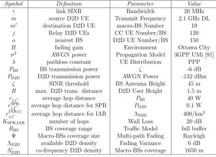
3.1 A comparison of Monte Carlo simulation and Stochastic Geom-etry. . . 41
3.3 A point process in time. . . 47
3.4 Cellular BSs location modeled va PPP. . . 48
3.5 A PCP modeled network, the red stars are the parent points
(BSs) and the blue circles are the UEs . . . 49
3.6 CC between two UEs with interference from neighbouring BSs
and other UEs . . . 51
3.7 D2D downlink communications between two UEs with
interfer-ence from neighbouring BSs. . . 52
3.8 D2D uplink communications between two UEs with interference
from other UEs. . . 53
4.1 3D building model (m2) of a section in Ottawa city model. . . 61
4.2 UE propagation path loss models in urban environment. . . . 62
4.3 BS Path Loss model of LOS and NLOS. . . 63
4.4 RBR data frame structure. . . 65
4.5 Interference-Aware-Routing (IAR): 3-Stage Process . . . 68
4.6 Simulated D2D Routing Paths in Ottawa city between
Trans-mitter UE and Receiver UE for Shortest-Path-Routing (SPR) and Interference-Aware-Routing (IAR). The diagram is under-laid with the interference power received at each location. Stars represent outdoor UE positions. . . 69 4.7 D2D outage probability as a function of the ratio between D2D
distance and cell coverage diameter. . . 70 4.8 D2D routing success probability as a function of D2D UE density. 72 4.9 D2D routing success probability as a function of building outer
wall penetration loss (dB). . . 73 4.10 The CC success probability with different number of D2D active
UEs pairs. . . 74
5.1 D2D multi-hop communications from m to m0 under SPR or
IAR algorithms. . . 79
5.2 D2D UEs coverage boundary and maximum potential
forward-ing distance for each sforward-ingle hop. . . 80
5.4 The success probability of SPR D2D at different locations: x
and y axes are the distance ratio scale ofro,m and ro,m0 toRBS. 88
5.5 The success probability of IAR D2D at different locations: x
and y axes are the distance ratio of ro,m
RBS and
ro,m0
RBS. . . 90
5.6 A snapshot of the simulation setup consisting of D2D UEs mov-ing inside the coverage area of a smov-ingle BS. . . 92 5.7 The theoretical number of hops for IAR and SPR routing schemes
compared with the box plot plot of their simulation results. . . 93 5.8 The theoretical capacity for IAR and SPR routing schemes
com-pared with the box plot of their simulation results. . . 95 5.9 Compression of success probability with theory (line) and
sim-ulation (symbol) as a function of the minimum distance from BS to one of the source and destination UEs: min[ro,m, ro,m0]. . 97
5.10 The interference routing algorithm in a cell set: the distance ratio scale of ro,m and ro,m0 to RBS. . . 98
6.1 Illustration of three different routing paths: intra-cell; intra-cell to cell boundary; and cell boundary to cell boundary. . . 105 6.2 Illustration of multi-hop routing from a sourcemto destinations
m0 with three different possiblem0 locations (the distance ro,m0
is constant). . . 107 6.3 Collision probability for intra-cell and intra-cell to cell boundary
routing paths with the distance scale of ro,m0 and ro,m, and CA
radius ratio (rCA/rcell) is 27%. . . 111
6.4 Collision probability (theory) for D2D intra-cell routing with different distances ro,m0, ro,m (as a function of cell coverage
ra-dius ro,m0 =ro,m). . . 112
6.5 Collision probability of theory and simulation results for D2D multi-cell routing with different CA radius ratios. . . 113 6.6 Gradient of the collision probability as a function of the
nor-malized distance along the source-destination route. . . 114
7.3 The Routing Paths for D2D LTE-U with SPR using LBT con-tention. . . 123 7.4 The balance equation . . . 125 7.5 The theoretical prediction of D2D UE waiting probability under
different traffic conditions with the Wi-Fi UEs density compared with simulation . . . 128 7.6 The theoretical prediction of D2D package delay under different
traffic conditions with the Wi-Fi UEs density compared with simulation . . . 129
7.7 The Wi-Fi capacity attenuation with different LTE-U COT and
Acknowledgments
I would like to express my sincere gratitude towards my supervisors, Dr. Weisi
Guo and Dr. Akeel Shah. It is my greatest fortune and pleasure to have their
guidance during my Ph.D. journey.
I would also like to thank Dr. Daciana Iliescu and Dr. Zuoyin Tang
for agreeing to be my Ph.D. examiners and their valuable suggestions and
comments on my thesis.
I am grateful to my family who have shown their full support throughout
my education life. There is no words that could express my love to them. My
wife Weixian Xu, my son Tianze Yuan, my parents Ronghua Yuan, Juhua Dai,
my parents-in-law Shusong Xu, Shiqin Wang, and my sister Wei Yuan and her
husband Yu Rong.
My study would not have been complete without the help and the
friend-ship of my friends, specially Xiayang Wang, he always hold a place in my happy
Declarations
I herewith declare that this thesis contains my own research performed under
the supervision of Dr. Weisi Guo and Dr. Akeel Shah, without assistance of
third parties, unless stated otherwise. No part of this thesis was submitted for
a degree at any other universities.
Hu Yuan
List of Publications
Journal
1. Y. Wu, W. Guo, H. Yuan, S. Wang, X. Chu, J. Zhang,“Device-to-device
Meets LTE-Unlicensed”, in IEEE Communications Magazine, vol. 54,
no. 5, May 2016, pp. 154-159.
2. H. Yuan, W. Guo, Y. Jin, S. Wang, M. Ni, “Interference-Aware Multi-Hop Path Selection for Device-to-Device Communications in a Cellular
Interference Environment” Submitted to IET Communications, 2017.
(Accepted)
Conference (Peer Reviewed)
1. H. Yuan, W. Guo, and S. Wang, “Emergency route selection for D2D cellular communications during an urban terrorist attack”, in IEEE In-ternational Conference on Communications Workshops (ICC), Sydney, Jun. 2014, pp. 237-242.
2. H. Yuan, W. Guo, and S. Wang, “D2D Multi-Hop Routing: Colli-sion Probability and Routing Strategy with Limited Location
Informa-tion”, inIEEE International Conference on Communications Workshops
(ICC), London, Jun. 2015, pp. 681-685.
3. H. Yuan, W. Guo, S. Wang, “Device-to-device Communications in
LTE-Unlicensed Heterogeneous Network”, in IEEE International workshop
Abbreviations
2G the second generation wireless systems
3G third generation wireless systems
4G the fourth generation wireless systems
5G the fifth generation wireless systems
3GPP Third Generation Partnership Project
ACK Acknowledgement
AP access points
BR broadcasting algorithm
BS base station
CA Collision Area
CC conventional cellular communication
CCA Clear Channel Assessment
CDF cumulative distribution function
CID connection identifier
COT Channel Occupancy Time
C-RAN cloud based radio access network
CSI channel state information
CSMA Carrier Sense Multiple Access
CTS clean to send
D2D Device to-device communications
DF decode-and-forward
DL downlink
EPC evolved packet core
E-UTRAN evolved universal terrestrial access network
fBS femtocell base station
FFD frequency division duplex
FLQ FlashLinQ
FSPL Free-space path loss
GPS Global Positioning System
GPSR Greedy Perimeter Stateless Routing
IAR interference aware routing
ICS Idle Channel Sense
ILA interference limited area
IPE inverse power echo
ISM The industrial, scientific, and medical radio band
LBT Listen Before Talk
LOS Line-of-Sight
LTE Long Term Evolution
LTE-A Long Term Evolution Advanced
LTE-U Long Term Evolution Unlicensed
MIMO Multi-input-multi-output
MMPP Markov modulated Poisson process
NLOS Non-Line-of-Sight
NSPS national security and public safety
OFDMA Orthogonal Frequency Division Multiplexing
PCP Poisson Cluster Process
pdf probability density function
PL Path loss
PLMN public and mobile network
PPP Poisson point process
PPDR public protection and disaster relief
ProSe Proximity-based Services
RB resource block
RBR restricted broadcasting algorithm
RRM radio resource management
RTS ready to send
SBR Shooting and Bouncing Ray
SCAT carrier-sensing adaptive transmission
SIC successive interference cancellation
SINR signal-to-interference-plus-noise-ratio
SPR shorted path routing
TDD Time Division Duplex
UE user equipment
UL uplink
List of Symbols
A area of a 2-D space
B a set of Euclidean space
B channel bandwidth
C network capacity
C average capacity
c the speed of light in a vacuum
f signal frequency (in hertz)
H fading gain
I interference
j Relay D2D UEs
KSPR,IAR number of hops
m source D2D UE
m0 destination D2D UE
N number of points in a space
o nearest BS
PBS BS transmission power
PD2D D2D transmission power
PCA collision probability
rCA collision area size
Q() Q function
Q(ζ, α)
q
ζ
B −1arctan
q
ζ B −1
for α= 4
Rd ad-dimensional Euclidean space
R max. D2D trans. distance
rj,j0 average hop distance
rSPR
rIAR(j,j0 i) average hop distance for IAR
RBS BS coverage range
Λ density of point process
ΛD2D available D2D density
Λ0D2D co-frequency D2D density
λ pathloss constant
Γ(·) the Gamma function
1b(0, rP) (xi) the indicator function of the condition xi ∈(0, rP).
µ mean service ratio
τ mean arrive ratio
γ link SINR
σ2 AWGN power
ζ SINR threshold
Abstract
Over the past decade, the proliferation of internet equipment and an
increasing number of people moving into cities have significantly influenced
mobile data demand density and intensity. To accommodate the increasing
demands, the fifth generation (5G) wireless systems standards emerged in
2014. Device-to-device communications (D2D) is one of the three primary
technologies to address the key performance indicators of the 5G network.
D2D communications enable devices to communicate data information directly
with each other without access to a fixed wireless infrastructure. The potential
advantages of D2D communications include throughput enhancement, device
energy saving and coverage expansion. The economic attraction to mobile
op-erators is that significant capacity and coverage gains can be achieved without
having to invest in network-side hardware upgrades or new cell deployments.
However, there are technical challenges related to D2D and
conven-tional cellular communication (CC) in co-existence, especially their mutual
interference due to spectrum sharing. A novel interference-aware-routing for
multi-hop D2D is introduced for reducing the mutual interference.
The first verification scenario of interference-aware-routing is that in a
real urban environment. D2D is used for relaying data across the urban terrain,
in the presence of CC communications. Different wireless routing algorithms
broadcast-routing. In general, the interference-aware-routing achieves a better
performance of reliability and there is a fundamental trade-off between D2D
and CC outage performances, due to their mutual interference relationship.
Then an analytical stochastic geometry framework is developed to compare the
performance of shortest-path-routing and interference-aware-routing. Based
on the results, the spatial operational envelopes for different D2D routing
al-gorithms and CC transmissions based on the user equipment (UEs) physical
locations are defined. There is a forbidden area of D2D because of the
inter-ference from the base stations(BSs), so the collision probability of the D2D
multi-hop path hitting the defined D2D forbidden area is analysed. Depend
on the result of the collision probability, a dynamic switching strategy between
D2D and CC communications in order to minimise mutual interference is
pro-posed. A blind gradient-based transmission switching strategy is developed
to avoid collision within the collision area and only requires knowledge of the
distances to the serving base station of the current user and the final
destina-tion user. In the final part of my research, the concept of LTE-U (Long term
evolution for Unlicensed Spectrum), which suggests that LTE can operate in
the unlicensed spectrum with significant modifications to its transmission
pro-tocols, is investigated. How the envisaged D2D networks can efficiently scale
their capacity by utilising the unlicensed spectrum with appropriately designed
Chapter 1
Introduction
1.1
Background
Over the past decade, two factors have significantly influenced mobile data
demand density, the first of which is the proliferation of internet equipment
(smart-phones, Phablets, machine-to-machine, laptops and tablets), which has
led to an explosive demand for mobile multimedia services. According to the
2016 Ciscor Visual Networking Index (VNI) report, in 2015 the number of
high-end devices grew from 563 million to 7.9 billion, and there will be 11.6
billion such devices by 2020. The rapidly increasing number of devices means
that mobile data traffic demand is expected to grow to 30.6 exabytes per month
by 2020, more than eight times that in 2015, as shown in Figure 1.1, where
CAGR is Compound Annual Growth Rate.
The second factor is that an increasing number of people now live in
cities [2]; for the first time in history, more than half of the human population
live in cities. Whilst over 80% of the population are urban in the developed
There-3.7EB
6.2EB
9.9EB
14.9EB
21.7EB
30.6 EB
0 5 10 15 20 25 30 35
2015 2016 2017 2018 2019 2020
Exabytes per month
53% CAGR 2015-2020
Compound Annual Growth Rate (CAGR)
Figure 1.1: Cisco Forecasts per Month of Mobile Data Traffic by 2020 [1].
fore, not only is the mobile data demand per person (Mbits/s/user) growing,
but the demand per unit area (Mbits/s/km2) has been growing at an even
greater rate in cities. Combining rapid mobile data growth and fast
urban-isation trends, one can draw the conclusion that there will be an extremely
high density of mobile communication devices in cities, mainly demanding
multimedia services [1].
0 5 10 15 20 25 30 35
2015 2016 2017 2018 2019 2020
Exabytes per Month
4G 3G 2G
10% 43% 47%
<1%
27%
[image:24.595.163.480.115.318.2]72%
Currently, 47% of the mobile traffic is transferred through 4G
connec-tions and the volume of traffic will grow faster than in other networks (2G, 3G)
to 72% of all mobile data traffic by 2020, as shown in Figure 1.2. To
accommo-date increasing digital data demands, Third Generation Partnership Project
(3GPP) proposed an enhanced Long Term Evolution (LTE) radio interface
called LTE-Advanced (LTE-A). Its radio interface is designed with carrier
ag-gregation [3–5], Massive Multi-input-multi-output (MIMO) [6, 7], millimeter
waves and low-power nodes to provide a higher network capacity.
The fifth generation wireless systems (5G) emerged in 2014, and they
aim to offer super-efficient mobile network, super-fast mobile network and
con-verged fiber-wireless network [8]. The expectations of the 5G network would be
1,000 times higher network capacity than the 4G network and a cell data rate
of 10 Gbit/s. The end to end latency is between 2 ms and 5 ms. The network
densification is 1000 times higher than the 4G network and with a very high
energy efficiency. The 5G network can offer lots of advanced services, such
as smart city, internet of things. The primary technologies and approaches to
address the key performance indicators are identified as [9]: Device-to-device
communications (D2D), Massive-MIMO, millimeter wave (mm-Wave)
commu-nications technologies, energy-aware communication and energy harvesting,
cloud based radio access network (C-RAN) and visualisation of wireless
re-sources. The visions of 5G networks and the corresponding technologies are
shown in Figure 1.3.
The concept of D2D communication in co-existence with cellular
net-works has been proposed and analyzed [10, 11]. D2D communications enable
devices to communicate directly with each other with assistance by the
Items 5G Expectations and Features Trends/Proposal
Capacity and throughput
1000 times of throughput, cell data rate a ~10 Gb/s, signalling loads less than 100%
Spectrum reuse, different band, C-RAN, massive-MIMO, D2D
Latency 2 to 5 ms end-to-end latencies C-RAN, D2D, and Full-duplex
Network densification 1000 times mobile data, 10000 times number of connecting
Heterogeneous networks, multi-tier network
Advanced services smart city, service-oriented M2M communication
Energy efficiency 10 times battery life Wireless charging, energy harvesting
Figure 1.3: Features and trends of 5G networks.
mobile user equipment (UEs) and allowing multi-hop transmissions of delay
tolerant data between UEs.
1.2
D2D in 3GPP Standardization
The 3GPP launched the first version of D2D communications in 2012 [12](3GPP
Release 12). In this release, potential requirements for a Base Station (BS)
controlled discovery and communications between devices that are in
proxim-ity under a Conventional Communication (CC) network coverage is identified.
UE ProSe APP
E-UTRAN
UE ProSe APP
EPC S1
ProSe APP Server SGi
ProSe Function PC 4
PC2
PC5 Uu
PC 3
PC 1 PC6
Uu
1.2.1
Architecture Enhancements to Support D2D
To enable D2D Communications in a cellular network, a new architecture has
been presented in [13], based on the existing LTE-A network. The supporting
D2D LTE-A architecture is composed of the evolved packet core (EPC) and
the evolved universal terrestrial access network (E-UTRAN), as shown in 1.4.
For the network side two new functions are introduced in [14], Prose Function
and Proximity-based Services (ProSe) Application Server; for the D2D UE
side, a ProSe Application is enabled to support the D2D.
The ProSe Functions are: (1) providing parameters for D2D discovery
and D2D communications, (2) identifying specific D2D applications and
sup-ports by the CC network, and (3) provide the network-related functions. The
ProSe Application Sever is studied in [15], in which the authorization of D2D
communications and discovery is handled over interface PC3 and the interface
PC5 between two D2D UEs is also presented.
1.2.2
D2D Communication Scenarios
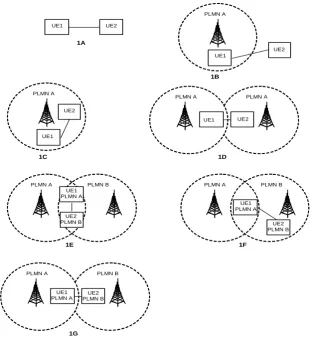
The architecture to support the ProSe is studied in [13]. The possible scenarios
of direct communication without a relay are shown in in Figure 1.5. There
are two main different coverage scenarios: (1) outside the public and mobile
network (PLMN) coverage, and (2) within the PLMN coverage. For a UE
acting as a relay, it can be UE-to-network relay or UE-to-UE relay.
The security of D2D communications is addressed by 3GPP in [16],
which contains a study of all potential security risk of D2D and an evaluation
of possible technical solutions needed to support such services. These
PLMN A
1A
PLMN A PLMN A
1B
UE2 UE1 PLMN A
1C 1D
PLMN A PLMN B
1F
UE1 PLMN A UE1 UE2
UE1
UE2
UE1 UE2
UE2 PLMN B PLMN A PLMN B
1E
UE1 PLMN A
UE2 PLMN B
PLMN A PLMN B
1G
UE1 PLMN A
[image:28.595.163.479.106.445.2]UE2 PLMN B
Figure 1.5: ProSe direct communication scenarios without a relay.
and privacy. The management of D2D communications is studied in [17], in
which management objects that are used to configure the D2D UEs are defined.
1.3
The Application Areas of D2D
The D2D proximal discovery services provide an always-on device discovery of
friends, services and offers in UEs’ proximity [18]. D2D enabled mobile devices
can discover things relevant to you, knowing what is around you, sensing your
environment, and learning your preferences. There are plenty of applications
Figure 1.6: Proximity: Service logic (Local Advertising) [19].
1.3.1
Commercial services
The D2D commercial services are based on the D2D proximity discovery
ser-vice, and the connected D2D UEs are always managed by the LTE network.
As an example of the nearby alerted services, Figure 1.6 shows a case study of
the precision advertising application presented by Telecom Italy Group [19].
A vendor launch a nearby announcement, once the request is verified by the
LTE network, the vendor can send the promotion to the nearby D2D enabled
UEs. Similar applications are gaming, entertainment and social media. Each
UE could be a social media which launched a new social networking [20].
1.3.2
Public safety applications
One of the key requirements of the public safety network is that it should
be stable (not affected by the environment or network traffic) and be able to
In almost all outdoor and most indoor areas, the cellular network can provide
network coverage and communication demands. However, for some scenarios
it is impossible, e.g. in long tunnels, deep inside a building with severe wall
penetration loss or if the CC network suffers severe damage from either natural
disasters or targeted attacks. D2D communication can be used for relaying to
provide expanded network coverage, or to boost network capacity when the
cellular network is congested.
Another advantage of D2D communication for public safety is group
communication. The D2D communications allows a one-to-many
communi-cation feature; for an emergency situation the dispatcher can broadcast
in-formation to multiple UEs at same time, which can significantly shorten the
emergency response time. Some research proposes D2D communication to
pro-vide public protection and disaster relief (PPDR) and national security and
public safety (NSPS) services [22, 23].
1.4
Research Contributions
For conventional wireless multi-hop, current research has focused on: i) how
to incorporate feedback mechanisms to ensure greater routing reliability [24];
ii) how to optimise partner selection to exploit spatial diversity [25–27]; and
iii) how to optimise spectrum sharing and power control for increased
energy-and spectral-efficiency [28–30].
When one considers multi-hop routing in the context of D2D
commu-nications, a major modeling consideration is the mutual interference between
the overlay macro-BS tier and the temporarily formed underlay D2D tier, as
This is a dynamic problem with many variables such as the location of the
source-destination UE pair and the overall network state. Multi-hop routing
selection under a cellular interference environment has not been extensively
studied at the time of conducting my research and my research mainly focus
on the D2D multi-hop routing.
D2D communication can utilize unlicensed spectrum as well [31], such
as the LTE-unlicensed spectrum specifically 5 GHz spectrum [32]. The
exist-ing 5 GHz unlicensed networks (802.11.n/802.11.ac) are usexist-ing Carrier Sense
Multiple Access (CSMA) for channel collision avoidance, but the D2D network
is a demand-based system.
In this thesis, my contributions are summarised as follows:
1. An extensive and detailed overview of D2D multi-hop routing, the
pro-tocol exchange between D2D UEs and coexisting technologies between
D2D using unlicensed and Wi-Fi system. Related to the publication of:
“Y. Wu, W. Guo, H. Yuan, S. Wang, X. Chu, J. Zhang,“Device-to-device
Meets LTE-Unlicensed”, in IEEE Communications Magazine, vol. 54,
no. 5, May 2016, pp. 154-159.”.
2. An improved broadcasting algorithm (BR), restricted broadcasting
al-gorithm (RBR), is addressed by solving the overload signaling challenge
of BR. Furthermore, an interference aware routing (IAR) is introduced
for the D2D multi-hop routing, which efficiently reduces the mutual
in-terference between D2D and CC networks. For an emergency D2D
com-munications, the application of RBR, shorted-path-routing (SPR), and
IAR is addressed and the performance is compared. Related to the
for D2D cellular communications during an urban terrorist attack”, in
IEEE International Conference on Communications Workshops (ICC), Sydney, Jun. 2014, pp. 237-242.”.
3. An analytical stochastic geometry framework comparing the performance
of SPR and IAR is developed and the spatial operational envelopes for
different D2D routing algorithms and CC transmissions based on the
UEs physical location are defined. Related to the submitted to: “ H.
Yuan, W. Guo, Y. Jin, S. Wang, M. Ni, “Interference-Aware Multi-Hop
Path Selection for Device-to-Device Communications in a Cellular
Inter-ference Environment” Submitted to IET Communications, 2016.”.
4. Based on a spatial operational zone, it is found that there is an area not
suitable for D2D communication because of the interference from BS.
The possibility of D2D routing path passing through the area is
anal-ysed. As a result, a gradient based switching mechanism between D2D
and CC is devised. Related to the publication of: “H. Yuan, W. Guo,
and S. Wang, “D2D Multi-Hop Routing: Collision Probability and
Rout-ing Strategy with Limited Location Information”, in IEEE International Conference on Communications Workshops (ICC), London, Jun. 2015, pp. 681-685.”.
5. The fairness of the channel occupation time between the D2D operating
in the industrial, scientific, and medical radio band (ISM) and the 802.11
network is examined, and the network performance and time delay for
both D2D and Wi-Fi UEs are analysed. Related to the publications of:
“H. Yuan, W. Guo, S. Wang, “Device-to-device Communications in
on Signal Processing advances in Wireless Communications (SPAWC), Edinburgh, July, 2016, pp. 1-5.” and “Y. Wu, W. Guo, H. Yuan, S.
Wang, X. Chu, J. Zhang,“Device-to-device Meets LTE-Unlicensed”, in
IEEE Communications Magazine, vol. 54, no. 5, May 2016, pp. 154-159.”.
1.5
Thesis Outline
The main topic of this thesis is the D2D multi-hop routing selection, which
in-cludes routing selection in underlaying cellular networks and the LTE-Unlicensed
spectrum. The thesis is organised as follows.
Chapter 2 presents a overview of D2D communications. A review of
different band spectrums for D2D communications is provided, where their
performance merits and limitations are discussed. A review of D2D multi-hop
routing algorithms is also presented, where the difference between the D2D
routing and the traditional Ad hoc routing is discussed.
In Chapter 3 the wireless communication network modelling is
ex-plained, with the two main modelling theories: Stochastic Geometry modelling
and Monte Carlo simulation.
In Chapter 4 the dynamic selection of multi-hop routes for D2D
commu-nications co-existent with a fully loaded urban cellular network is addressed,
when the cellular network is congested during an unexpected event. Three
dif-ferent wireless routing algorithms, shortest-path-routing (SPR),
interference-aware-routing (IAR) and restricted broadcast-routing (RBR), are analysed.
Chapter 5 develops a theoretical stochastic geometry framework, which
bounds on the operation envelopes of the different D2D routing algorithms can
be entirely characterized by clear geometric regions in the coverage area of the
cell.
In Chapter 6, a collision area (which is defined as that the D2D
com-munication cannot satisfy the minimum SINR requirement because of the
in-terference from BSs) in a heterogeneous cellular network for the purpose of
interference management between D2D and CC is defined. In the absence of
accurate location information, the collision probability of the D2D multi-hop
path hitting the defined collision area is analysed.
Chapter 7 considers how the envisaged D2D networks can efficiently
scale its capacity by utilising the unlicensed spectrum with appropriately
de-signed LTE-Unlicensed (LTE-U) protocols are examined. The LTE-U Listen
Before Talk (LBT) algorithm with multi-hop routing is adapted for collision
avoidance between traditional unlicensed UEs, e.g. Wi-Fi UEs, and the LTE-U
enabled D2D UEs.
The research results and findings presented in the thesis are summarised
Chapter 2
Review of Device-to-Device
Communication
In this chapter, the motivation to study D2D communications and its status
within the cellular network eco-system is discussed. Then, two prominent
research challenges in multi-hop D2D communications underlaying cellular
networks are reviewed: band selection (inband and outband) and a variety
routing algorithms for multi-hop D2D communications are presented. Before
that, the communication performance benefits for D2D are reviewed, and then
the communication spectrum is investigated, inband and outband unlicensed
spectrum (802.11 protocol).
2.1
Overview of Communication Performance
Benefits
D2D communications, which is a part of the LTE-Direct standard [33], is
relaying messages using neighboring UEs [34, 35]. In terms of command and
control, each D2D connection will anchor on the serving BS, but the BSs
are avoided in terms of data-bearing channels. Hence, D2D communication
protocols are semi-distributed.
The conditions for establishing D2D communications in a cellular
envi-ronment include insufficient channel resources in the BS and the transmission
of delay tolerant data [36]. As for device discovery between potential D2D
UEs, it has been proposed that the UEs can utilize recent 3GPP ProSe
stan-dardization [37].
The potential advantages of D2D communications include throughput
enhancement, UE energy saving and coverage expansion [38,39]. The economic
attraction for mobile operators is that significant capacity and coverage gains
can be achieved without having to invest in network-side hardware upgrades or
new cell deployments. However, there are technical challenges related to D2D
and conventional cellular (CC) communications in co-existence, especially the
mutual interference due to spectrum sharing.
Enhanced Throughput. The rate of CC network can be enhanced by exploiting D2D communications as a relay [40, 41]. The idle UEs can act as
relay to help the CC UEs when they are in a poor link quality to transmit
data [42], so that the network throughput is enhanced. There is an obvious
challenge, how to manage the transmission model (whether via D2D relay or
CC). A transmission graph solution is presented in [43], where each UE (D2D
or CC) is represented by a vertex. The transmission mode selection (whether
to use D2D relay or CC) is formulated as a flow maximization problem.
Another approach to improve the network throughput is reusing the
how to manage the mutual interference of D2D and CC communication.
Sev-eral techniques have been investigated to suppress interference between D2D
and CC links, such as Successive Interference Cancellation (SIC) [44], Radio
Resource Management (RRM) [45] with game theory to prioritize
transmit-ters [46]. An SIC is proposed in [47], which is by reducing the interference
to D2D communication link can get capacity without dropping CC network
capacity. Radio spectrum management [48], whether the D2D UEs reuse the
cellular spectrum or the dedicated spectrum for D2D UEs by BS, is another
efficient way to reduce the mutual interference.
Extension of Coverage. D2D UEs serve as relays to cover UEs outside the cellular coverage. When a UE is not in the cellular coverage, another
D2D-enabled UE within the cellular coverage is selected as a relay to help the
UE communicate with the BS or other UEs with in coverage. The authors
in [49] describe the D2D acting as a relay for national security and public
safety (NSPS) services when the network coverage is partial or missing.
Energy Efficiency. Generally D2D communication is a shorter distance communication network compared with the CC network. So D2D needs lower
transmission power to get the same signal-to-interference-noise-ratio (SINR)
under the same interference environment. D2D communication can effectively
offload the CC network traffic [50, 51], and after the traffic is offloaded to D2D
UEs, the BS can set up as a sleeping control model when the network traffic
volume is below the threshold [52].
Spectrum Efficiency. The D2D communications can enhance the spec-trum efficiency by reusing the cellular specspec-trum. How to allocate the cellular
spectrum is a challenge. A cognitive spectrum access technology for spectrum
sens-ing the received interference for any D2D receiver. When the two D2D UEs
prepare to communicate, the transmitter sends a communication request to
the intended receiver first. Then the receiver senses the channel interference;
if the SINR is over the set threshold, the intended receiver replies a
communi-cation confirm message for establishing the D2D communicommuni-cation link. While
if the SINR is below the threshold, the D2D communication is not allowed.
2.2
D2D Band Selection
The D2D communication can utilize either the cellular spectrum (inband) or
unlicensed spectrum (outband). The outband spectrum can be unlicensed
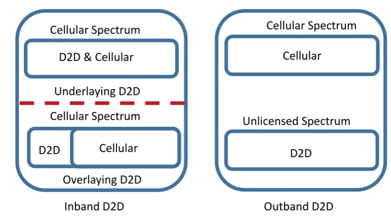
spectrum or allocated spectrum by BS [54]. For inband D2D, there are two
models to reuse cellular spectrum resources [55]: underlay inband or overlay
inband.
The licensed band of Frequency Division Duplex (FDD) LTE network
which is operated in Figure 2.1 shows the full frequency band allocations.
Industrial, scientific and medical (ISM) radio bands mainly focus on 433 MHz,
915 MHz, 2450 MHz and 5000 MHz.
2.2.1
Inband D2D
In underlay inband, D2D links use the same cellular network spectrum band
at the same time as the CC network. The underlay D2D would enhance
the spectrum efficiency by reusing the CC spectrum with CC network at the
uresame time but an obvious challenge is to manage the mutual interference
between D2D and CC network. In overlay inband D2D, the cellular network
FDD LTE BANDS & FREQUENCIES LTE BAND
NUMBER
UPLINK (MHZ)
DOWNLINK (MHZ)
WIDTH OF BAND (MHZ)
BAND GAP (MHZ)
1 1920 - 1980 2110 - 2170 60 130
2 1850 - 1910 1930 - 1990 60 20
3 1710 - 1785 1805 -1880 75 20
4 1710 - 1755 2110 - 2155 45 355
5 824 - 849 869 - 894 25 20
6 830 - 840 875 - 885 10 25
7 2500 - 2570 2620 - 2690 70 50
8 880 - 915 925 - 960 35 10
9 1749.9 - 1784.9 1844.9 - 1879.9 35 60
10 1710 - 1770 2110 - 2170 60 340
11 1427.9 - 1452.9 1475.9 - 1500.9 20 28
12 698 - 716 728 - 746 18 12
13 777 - 787 746 - 756 10 41
14 788 - 798 758 - 768 10 40
15 1900 - 1920 2600 - 2620 20 680
16 2010 - 2025 2585 - 2600 15 560
17 704 - 716 734 - 746 12 18
18 815 - 830 860 - 875 15 30
19 830 - 845 875 - 890 15 30
20 832 - 862 791 - 821 30 71
21 1447.9 - 1462.9 1495.5 - 1510.9 15 33
22 3410 - 3500 3510 - 3600 90 10
23 2000 - 2020 2180 - 2200 20 160
24 1625.5 - 1660.5 1525 - 1559 34 135.5
25 1850 - 1915 1930 - 1995 65 15
26 814 - 849 859 - 894 30 / 40 10
27 807 - 824 852 - 869 17 28
28 703 - 748 758 - 803 45 10
29 n/a 717 - 728 11
30 2305 - 2315 2350 - 2360 10 35
31 452.5 - 457.5 462.5 - 467.5 5 5
time slots of the channel to D2D links. The spectrum sharing is illustrated in
Figure 2.2.
Inband D2D Outband D2D
Underlaying D2D Cellular Spectrum
D2D & Cellular
Overlaying D2D Cellular Spectrum
D2D
Cellular
Cellular Spectrum
D2D
Unlicensed Spectrum
Cellular
Figure 2.2: The band spectrum situation for inband and outband D2D com-munication.
In overlaying D2D communications, BS allocates dedicated resources
for D2D communications [56–58]. The overlaying D2D eliminates the mutual
interference between the CC networks and D2D communications, however it
reduces the resources efficiency and the available resources for the CC network.
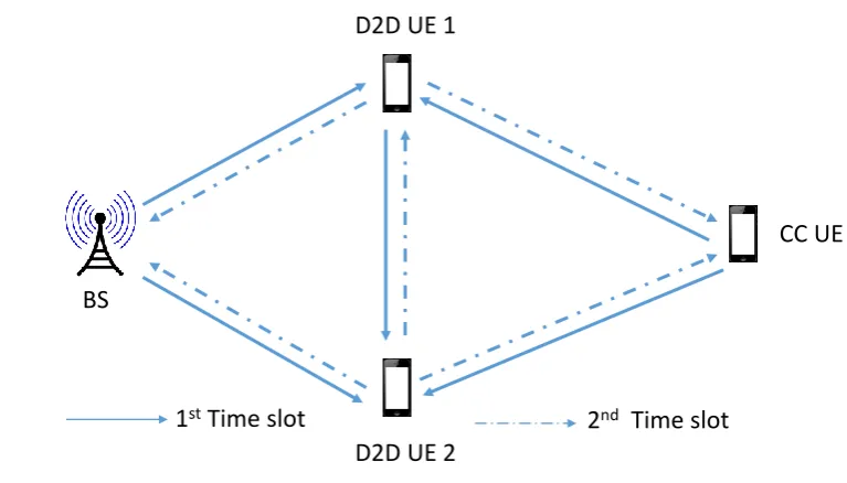
The communication channel is partitioned to different sub-channels on
the time domain for overlaying D2D communication, which is addressed in [40],
in which the authors considered a pair of D2D UEs as a two way relay between
CC UE and BS while the D2D can communicate with each other. At the first
time slot, BS and CC UE transmit data to the two D2D UEs and for the
second time slot the two D2D UEs transmit the data to CC UE and BS shown
in Figure 2.3. At each time slot, only one D2D UE can send message to the
D2D UE 1
D2D UE 2
CC UE
BS
[image:41.595.125.509.108.327.2]1stTime slot 2nd Time slot
Figure 2.3: The two different time slot protocol.
D2D UEs as a relay to communicate with the BS . The results shown in [40]
are that the overall network achievable rate increases for both the cellular links
and the D2D communications.
A frequency overlaying D2D communication with the different time slot
allocation is presented in [59]. The authors proposed an overlaying D2D
com-munications of a two-tier cellular network for offloading the network traffic and
enhancing the network rate. Each macro BS (distributed as a hexagon) has six
pico BSs at the end points of its borders, and the pico BSs maintain a mapping
table (which includes available frequency resource block (RB), channel state
information (CSI) and QoS requirements) to assist the D2D communication
establishment. The average rate of macro BSs, pico BSs and D2D
communi-cations is optimized based on the user density and pico cell coverage range.
The results show that D2D communication can significantly improve the per
allocation between pico BS and D2D communications. Similar work was
pre-sented in [60], where the authors addressed a downlink (DL) overlaying D2D
communications. The D2D UEs are allocated the dedicated DL spectrum
act-ing as a relay to extend the CC coverage; D2D UEs communicate with the CC
UEs who are outside the CC coverage.
2.2.2
Outband D2D Communication
The outband spectrum can be either unlicensed spectrum or allocated
spec-trum taken from the licensed band [31]. Outband D2D is advantageous
com-pared with underlaying D2D because there is no mutual interference between
D2D and CC UEs. For example, in [61] the industrial, scientific and medical
(ISM) band is selected for D2D communications in LTE. The D2D UEs are
grouped based on the different QoS requirements, whereby only one UE per
group can use the ISM band for communication.
D2D on Unlicensed Spectrum
During the past few years, the concept of LTE-U (LTE for Unlicensed
Spec-trum) has been addressed, which suggests that LTE can operate in the
unli-censed spectrum with significant modifications to its transmission protocols.
LTE-U must adhere to unlicensed spectrum requirements, i.e., set transmit
power limits and collision avoidance [32]. By utilizing the considerable amount
of unlicensed spectrum available, low power D2D transmissions can potentially
avoid cross-tier interference with CC channels, at the cost of complicating the
unlicensed spectrum usage [62]. LTE-U has been included in 3GPP Release 13
rates [62].
Wi-Fi is a contention-based system with an appropriate mechanism
taken to avoid interference, i.e., CSMA. However LTE is a demand-based
sys-tem, so a critical element of LTE-U is to ensure fairness for Wi-Fi and other
unlicensed users. There are two main algorithms for a fairness to sharing the
unlicensed channel.
Idle Channel Sense
A straight approach is to sense the Wi-Fi channel. If the channel is empty, the
unlicensed communication is actived. If the channel is occupied then wait for
a clean channel. The difference between CSMA and Idle Channel Sense (ICS)
is that a CSMA system is applied with a collision avoidance (CA) mechanism.
When the transmitter senses a clear channel, it will send a ready to send
(RTS) frame. If the receiver is ready to receive it will send a Clean to Send
(CTS) package to inform transmitter. This protocol is also called RTS/CTS
handshake.
In [63], an example of LTE-U channel access scheme is presented, where
the femtocell base station (fBS) senses the unlicensed channel by detecting the
received power strength [64]. Before the fBS accesses the unlicensed channel,
it will detect the channel for a period Tsensing. If the channel is clean during
the sensing time, then the fBS accesses the unlicensed band and occupy the
channel for a fix timeTcellTx. If not, the fBS assigns the LTE licensed resource.
Another protocol is addressed in [65], which proposes an approach for
LTE-U UEs co-existence with the 802.11 protocol controlled by eNB. The eNB
is divided into two components, 802.11 part and LTE part. At the beginning,
LTE-U LTE-U
LTE-U On
LTE-U Off CSAT Duty Cycle
LTE-U
LTE-U On LTE-U On
LTE-U Off
Time Adaptive on/off duration
Wi-Fi access duration
Figure 2.4: CSAT enables LTE-U and Wi-Fi to share the same channel.
is empty, the LTE part of eNB will launch the communication with LTE UEs
on unlicensed band. At the same time, 802.11 part of eNB will broadcast
a Wi-Fi frame that notices the channel occupancy time to 802.11 UEs. If
there exists an 802.11 UE using the channel, the 802.11 part decodes the PHY
frame from 802.11 device and obtains its length and attributes information
(e.g. transmission power, maximum interference power that is tolerable by
802.11 receiver UE). According to the decoded information, the LTE part uses
a lower power communication with the LTE UEs on unlicensed band to satisfy
the interference requirement of the 802.11 UEs.
Carrier-Sensing Adaptive Transmission
Different from the ICS, Carrier-Sensing Adaptive Transmission (SCAT) is
based on duty cycle to control the LTE signal on and off, duty cycled
con-figuration does not sense the channel before transmitting [66]. As shown in
Figure 2.4 when the LTE-U is on, the LTE occupies the channel; while in the
LTE-U off period, the channel is unoccupied to neighboring Wi-Fi which can
resume normal Wi-Fi transmissions. During the LTE-U off period, the
uti-lization of Wi-Fi medium will be measured by LTE (normally LTE fBS), and
The duty cycle can be set to a few hundred milliseconds, which can effectively
accommodate the QoS requirement while controlling the data transmission
delay.
Compared with ICS, SCAT does not sense the channel before
trans-mission so that there is a probability of that two different different UEs are
transmission at same time( which is defined as a communication collision).
The collision reduces both LTE and Wi-Fi capacity. The research in [67]
shows that when the LTE-U on period is shorter than off period, the network
capacity of using SCAT is 13% lower than using ICS.
2.3
Review of Multi-hop Routing Algorithms
In D2D communications multi-hop network, how to select the best path is
a challenge. Routing is the process of selecting best paths in a network. In
wireless communication networks, routing directs data forwarding from the
source node to the destination through the specific nodes in the same network.
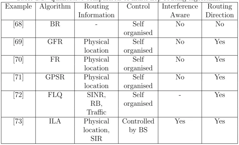
How to select the specific nodes is called the routing algorithm. A qualitative
comparison of multi-hop routing algorithm is given in Table 2.1.
2.3.1
Broadcasting Wireless Routing
Broadcasting (BR) refers to transmitting data to all other nodes within the
transmitter’s transmission range [68]. There are two main replication
algo-rithms: Flooding and Controlled flooding.
Flooding: The source node sends a copy of the data to all of its neigh-bors. When a node receives a broadcast data, it duplicates the data and
Table 2.1: Qualitative comparison of multi-hop routing algorithms.
Example Algorithm Routing Control Interference Routing
Information Aware Direction
[68] BR - Self No No
organised
[69] GFR Physical Self No Yes
location organised
[70] FR Physical Self No Yes
location organised
[71] GPSR Physical Self No Yes
location organised
[72] FLQ SINR, Self - Yes
RB, organised
Traffic
[73] ILA Physical Controlled Yes Yes
location, by BS
SIR
have a copy of the packet. As shown in Figure 2.5, the source nodesbroadcasts
data to nodej1. Thenj1 duplicates to all its neighbors.
However, when a node is connected to more than two other nodes, it
will create and forward multiple copies of the broadcast data. It is result to
the endless multiplication of broadcast data [68]. As shown in Figure 2.5, an
endless multiplication of broadcasting is between nodej1,j2, and j3.
Controlled flooding: By solving the problem of endless multiplication in BR, a controlled flooding algorithm is addressed in [74] which is also known
as Controlled flooding BR. The process of the algorithm is shown as:
1. A source node puts its sequence number i into a broadcast data, which
is set up as 1.
2. The source sends the packet to all of its neighbors.
s
j
1
d
j
3
j
2
Figure 2.5: The broadcasting routing with flooding.
number as i+ 1, then broadcast data they have received. Each process
of broadcasting increases the sequence number by 1.
4. When a node receives a broadcast data, it checks the data sequence.
If smaller than its own sequence number, the packet is duplicated and
forwarded, otherwise, the packet is dropped.
As shown in Figure 2.6, the BR with controlled flooding. Source UE
s wishes to transmit data to the destination UE d, but there is no direct
communication link betweensand d. In this figure, the source UEs is
broad-casting data to destination UE d. At the beginning, s sets its sequence as 1
and broadcasts to j1. After receives the data from s, j1 sets its sequence as
2 and forwards to j2 and j3. But j2 and j3 cannot replay back because their
sequences are bigger than j1. Therefore, the controlled broadcasting avoids
the endless multiplication of broadcast data.
However, BR causes overload signaling and when the data reaches the
challeng-s
j
1
d
j
3
j
2
Seq. 1
Figure 2.6: The broadcasting routing with controlled flooding.
ing.
2.3.2
Geographical Wireless Multi-hop Routing
The problem of BR is lack of direction, there is no route direction for where the
data should be transferred. For solving those problems, a geographical location
based routing algorithm is proposed in the 1980s by Hideaki Takagi [75].
Geographical routing is a routing protocol using information about the
geographic location of the neighbors of the current node to direct a packet to
its destination. In geographic routing protocols, it is assumed that all UEs
have the information of their own locations and that the source UE knows
location information of the destination UE. As we will see below, the
des-tination location information is passed from source UE to every relay node
during the relay nodes selections. Normally, UEs obtain their own geographic
coordinates with a Global Positioning System (GPS) [76] or a grid location
three popular Geographical multi-hop routing methods in the literature are
reviewed.
Greedy Forwarding Routing
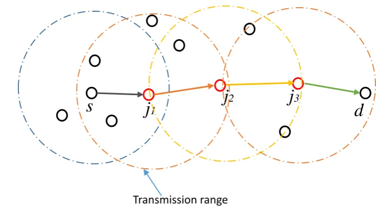
Greedy Forwarding Routing is an improved BR. As reviewed earlier in Section
2.3.1, in BR any UEs re-broadcast the data after receive the data, but in
Greedy Forwarding only the selected UEs can relay. Greedy forwarding is a
routing algorithm based on the network UEs’ physical locations, and it works
by forwarding a packet closer to destination [69]. When the source UE needs
to send data to a specific destination UE, it first checks its available neighbour
UEs to select the neighbour UE which is closest to the destination as the first
relay. Once the data is received, the relay UE will perform the same approach,
to determine the neighbours which is closest to destination and forward the
data to it as the next relay. The process is continued until the data reaches
the destination.
Figure 2.7 illustrates a greedy forwarding algorithm under the same
network scenario with BR. It is can be seen that the routing has a definite
directivity from s to d. Following the greedy forward routing, s selects its
neighbour UE j1 as which is closest to d within s transmission range. The
relay UE j1 repeats greedy process forward to next UE j2, repeating this
process until data reachesd.
A successful greedy forward routing requires among all the UEs
partic-ipating in the routing process, there should be at least one neighbour closer
to the destination than itself such as shown in 2.7. Realistically, this might be
impossible for a dynamic wireless network, therefore the UE cannot find a UE
s
j
1d
j
2j
3 [image:50.595.126.494.109.328.2]Transmission range
Figure 2.7: Wireless relay network via greedy forwarding algorithm.
a closer neighbour than itself tod. When a UE cannot find a neighbour closer
than itself to the destination, it will drop the data to avoid routing loop [78].
An alternative to greedy routing is face routing which avoids this problem.
Face Routing
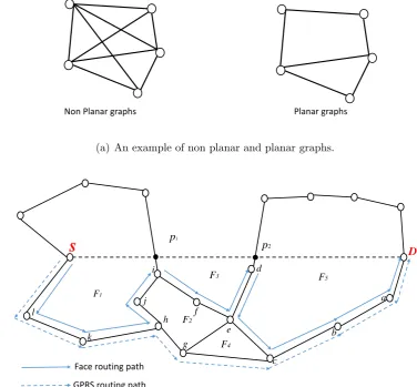
In face routing, a geometric routing algorithm is applied to a planned subgraph
of network topology [70]. A planar subgraph divides the network topology
plane into different faces, where each planar subgraph contains no intersecting
edges and is composed of polygonal regions separated by edges [79,80]. Figure
2.8(a) shows an example of planar graphs.
Once the planar subgraph has been obtained, the data from source UE is
forwarded along the first face boundary in anticlockwise (from the source to the
destination) order until it reaches the source-destination-line (S-D-line) shown
Non Planar graphs Planar graphs
(a) An example of non planar and planar graphs.
s
p2p1
D
F1
F2
F4
F5
F3
Face routing path GPRS routing path
a
b
c d
e f
g h i
j
k l
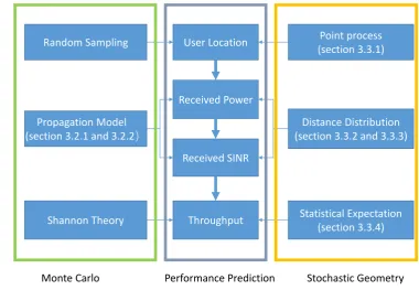
[image:51.595.126.503.124.473.2](b) An example of the path followed by a packet using a face routing protocol and Greedy Perimeter Stateless Routing.
Figure 2.8: The planar graphs and face routing.
other faces at the edges crossing the S-D-line until it reaches the destination
UE [81]. Figure 2.8(b) shows an example of the routing computed by face
routing protocol. The route starts from source UE S to destination UE d, it
first travels inside the face F1 until reaches UEi. If continuing to route in F1
it will reach the intersection point by S-D line and face boundary line, called a
face broken pointp1. Therefore, it has to change routing face, under the right
travels along the boundaries of faces F3 when reaches d and then changes to F5 until delivered to destination D.
Ideally, planar subgraphs are connected as planarization with full
con-nectivity, but in reality specifics of a wireless environment mean planar
sub-graphs may lack connectivity, such as node a does not exist in Figure 2.8(b),
when node b cannot find a next relay, and it will switch to anticlockwise
or-der. If anticlockwise and clockwise order both fail, the network routing fails
to connect the destination.
Another problem is that it is not the shortest route. As shown in Figure
2.8(b) when data arrives the relay UEh, the shortest path ish−g−cbut for
facing routing it ish−j−i−f−e−d−c. The longer routing path causes longer
time delay and more energy consumption due to a larger number of hops. A
combined greedy routing and face routing called greedy perimeter stateless
routing (GPSR) algorithm to enhance the routing efficiency is proposed.
Greedy Perimeter Stateless Routing (GPSR)
The greedy perimeter stateless routing (GPSR) algorithm uses graph-theoretic
techniques to find routes, and exploits the correspondence between geographic
positions and connectivity in a wireless network to make packet forwarding
decisions [71]. It will start in greedy forward routing and then switch to face
routing when the current UE cannot find a neighbour closer to the destination
than itself. In particular, it employs:
1. greedy mode which is the priority mode, forward data to neighbour UE that is closer to the destination;
data traverses successively closer faces of a planar sub-graph of the full
connectivity graph until reaching a UE closer to the destination, and
then the greedy mode resumes.
Geographical Routing based on the location information can provide a
definite directivity for the routing path. However, for a wireless
communica-tion network the channel status (such as channel throughput, traffic volume or
SINR) is also an important parameter for the network. Geographical Routing
does not consider the channel status when selecting the routing path.
Atten-tively, a channel status based routing algorithm called FlashLinQ is reviewed
in the next section.
2.3.3
FlashLinQ Routing Algorithm
FlashLinQ (FLQ) is a technology of PHY/MAC network architecture for
syn-chronous and distributed D2D communication [72], which was introduced by
QualComm, aiming to find a maximal channel-state-aware subset of channel
links. FLQ is suitable for D2D coexisting communication under a condition
of QoS, e.g. SINR, traffic volume. In FLQ, a synchronous Time Division
Du-plex (TDD) Orthogonal Frequency Division MultiDu-plexing (OFDM) system is
designed at 2.586 GHz carrier frequency with 5 MHz bandwidth. Each device
identifies its neighbouring devices by receiving single-tone discovery signals.
In the architecture of FlashLinQ, the available links between D2D UEs
are distributed as two matrices for both transmitter and receiver, and each one
has 112 RB, where an RB represents a sub-channel and an OFDM symbol.
The links are assigned to different priorities ordered from 1st to nth. For a
Connection scheduling
Rate
scheduling Data transfer ACK
Tx block Rx block Direction CQI
Figure 2.9: The structure of traffic channel (TCCH)
following requirements:
1. Both transmitter UE and receiver UE agree the channel SIR;
2. The signal over linknwill not cause interference to any already scheduled
link with a higher priority, e.g. link {1, 2, 3, ..., n-1};
3. Both transmitter and receiver UEs’ corresponding RBs are available.
D2D links perform link scheduling according to the scheduling results
in a traffic channel (TCCH) frames in the data transfer phase shown in Figure
2.9. In the link scheduling period of the traffic channel, in order to determine
whether to access the link, transmitter (Tx) and receiver (Rx) in each active
D2D link schedules process by transmitting and detecting direct power signal
(DPS) and inverse power echo (IPE) signals in Tx and Rx OFDM blocks
respectively. Finally, Tx transmits data frames to Rx and Rx acknowledges
results of the data reception in the Data transfer and Acknowledgement (ACK)
periods.
The priority of different links is assigned randomly at each time slot,
so FLQ is fair for all links. A locally unique connection identifier (CID) is
can transmit simultaneously. A two-hop D2D communication with FLQ is
presented in [82]. The hop links are connected as:
• Source D2D UE m discovers destination D2D UE m0 based on FLQ;
• m identifies UE j as a relay for multi-hop communication based on the
first discovery results;
• m establishes the link m −j −m0 and transmits data from m to m0
relaying by j;
• m0 replay the confirm ACK to m through j, transmission completed,
release the link.
The RBs are limited to 112 in FLQ, for a high D2D UEs density, which
is not enough for dedicating the RB to each D2D communication link,
further-more dedicates RBs to D2D also reduces the cellular spectrum efficiency.
FLQ is a routing algorithm which depends on each UE maintaining a
routing table containing information of all available relay UEs and
geographi-cal routing protocol does not need to maintain the entire network topology. On
one hand, geographical routing reduces network cost due to the relatively low
amount of coordination and information exchange. On the other hand,
geo-graphical routing only requires information about neighbour UEs so it reduces
reliance of complete network topology.
2.3.4
BS Assistance for D2D Communications Routing
BR, geographical routing and FLQ are self-organised routing algorithms. They
the routing environment changes such as the movement of UEs and
commu-nication channel status changes. Furthermore, when the routing process fail,
there is not an efficiency backup algorithm. D2D communications is part of
LTE-Direct standard. The entire communication is controlled and authorised
by the BS. Therefore, the BS plays a significant role for D2D routing.
The BS assistance for D2D communication contains three main
func-tions at each hop: (1) register the identification (ID) of D2D UEs (such as
IMSI) and the D2D UE link layer identifier; (2) authorise the D2D UEs
prox-imity discovery whereby the open discovery technology is used (in open
dis-covery, the UEs can be detected by any other UE in its proximity [34] [83]);
(3) provide the destination UE location to the relay UEs. In the event that
the D2D multi-hop process fails, the BS will take over the communications
and establish a CC link.
Device Proximity Discovery
Before a source UE can communicate with the destination UE, it needs to
identify its neighboring UEs so that the data can be routed through the optimal
set of relay UEs to the destination. In order to set up a D2D link, the UE
transmits a device discovery signal for its nearby UEs to detect the signal. The
device discovery process can be classified intorestricted discoveryandopen
discovery[34]. In restricted discovery, D2D UEs must have a permission from
the BS to be detected by other UEs, while in open discovery, the UEs can be
detected by any other UE in its proximity.
As Figure 2.10 shows, the user of UE m (the discoverer) wishes to
discover whether there are any other D2D UEs in proximity. UEmbroadcasts
2a. Discovery Response (App Personal ID
of user 2)
UE4 (discoveree) UE3
(discoveree)
UE2 (discoveree)
UE m (discoverer)
UE mbroadcasts a Discovery Request (App Group ID , App Personal ID of user 1)
2b. Discovery Response (App Personal ID of
user 3)
2c. Discovery Response (App Personal ID of
user 4)
UE 1 (No D2D)
Figure 2.10: The D2D UE proximity discovery
• If a mobile UE is an active D2D UE, it replies a data frame with its
identifier ID set to the discover UE’s neighbour group, which is marked
as a potential D2D relay UE in the group;
• Alternatively, if the UE is not an active D2D UE, it may keep quiet to
the discoverer UE.
The discovery request message is received by UE1, UE2, UE3 and UE4.
Apart from the user of UE1, all other UEs are active D2D UEs. Each of UEs
responds directly to discoverer UE with a discovery response message which
may contain the unique personal ID of its user.
Data Relay Between UEs
As shown in Figure 2.11, the BS provides assistance between the D2D source
![Figure 1.2: Global Mobile Traffic by Connection Type by 2020 [1].](https://thumb-us.123doks.com/thumbv2/123dok_us/9498082.455382/24.595.163.480.115.318/figure-global-mobile-trac-connection-type.webp)
![Figure 1.6: Proximity: Service logic (Local Advertising) [19].](https://thumb-us.123doks.com/thumbv2/123dok_us/9498082.455382/29.595.125.478.112.326/figure-proximity-service-logic-local-advertising.webp)