BeanBag
An Extensible Framework
for Describing, Storing
and Querying Components
Caroline O’Reilly B.A. (Mod)
A dissertation submitted to the University of Dublin,
in partial fulfilment of the requirements for the degree of
Master of Science in Computer Science
Declaration
I declare that the work described in this dissertation is, except where
otherwise stated, entirely my own work and has not been
submitted as an exercise for a degree at this or any other
university.
Signed: ___________________
Date: 17-September-1999
Permission to lend and/or copy
I agree that Trinity College Library may lend or copy this dissertation upon
request.
Signed: ___________________
Abstract
When it became obvious that Object Oriented software applications were falling short
of their promise of significant software reuse, the software industry began to look at
another solution. Hence the interest in Component Technology. If developers have the
means to use off the shelf components, application development time can be reduced
and quality will improve. Components are by nature modularised and are more
maintainable than other software applications, with easy integration of component
versions. When companies want to minimise the expense of developing in-house
solutions and the inflexibility of bought-in software, components are introduced,
allowing assembly of components into customised solutions.
Presently, there are three main component driving forces, the OMG with the CORBA
Component Model (CCM), Microsoft with COM Components (COM) and Sun with
Enterprise Java Beans (EJB).
Enterprise Java Beans is the Java component architecture for developing server side
components, as opposed to Java Beans, which is used to develop client side
components. Threading, persistence, and security are handled by an EJB Container.
All types of components will have to reside in a repository for application developers to
find them. In time it will become crucial to be able to query this repository and to view
component descriptions. As the situation stands, the EJB Deployment Descriptor does
not provide enough semantic information for a developer to understand exactly what a
component does.
This thesis examines ways of storing components and extracting information
transparently from them. It also examines ways of describing component semantics in a
way that is extensible. Developers in the future, who realise that certain semantic
information is crucial in a component description can create descriptions in a controlled
way, and other developers can search this data. The descriptions developed are XML
documents, and can be applied to all types of components, even though this thesis
Acknowledgements
Many thanks to my supervisor Dr. Paddy Nixon and Sotirios Terzis for their valuable
ideas and encouragement. Thanks also to Malcolm and Peter from IONA for their XML
and EJB expertise and for always having the answers. The M.Sc. class was invaluable
in the final weeks for their humorous bantering in the early hours. Lastly, thanks to
1. INTRODUCTION... 1
1.1 MOTIVATION... 1
1.2 PROPOSED SOLUTION... 1
1.3 ACHIEVEMENTS... 2
1.4 ROADMAP... 2
1.5 SUMMARY... 2
2. LITERATURE SURVEY ... 3
2.1 INTRODUCTION... 3
2.2 SOFTWARE COMPONENT MOTIVATION... 3
2.2.1 The Benefits of Components ... 4
2.3 WHAT ARE SOFTWARE COMPONENTS?... 5
2.3.1 Components versus Other Kinds of Reuse ... 6
2.4 COMPONENT FRAMEWORKS... 8
2.4.1 Java Beans... 9
2.4.2 Enterprise Java Beans (EJB) ... 10
2.4.3 The CORBA Components Model (CCM) ... 16
2.4.4 COM Components ... 22
2.4.5 Commercial Application Servers ... 26
2.5 COMPONENT DESCRIPTION LANGUAGES... 27
2.5.1 IDL... 27
2.5.2 OCL ... 28
2.5.3 JBCDL ... 30
2.5.4 KDL ... 30
2.6 MODELLING LANGUAGES... 31
2.6.1 UML... 31
2.6.2 DESML ... 32
2.7 COMPONENT REPOSITORIES... 35
2.7.1 A Distributed Repository for Object-Oriented Software Components... 36
2.7.2 DELOS... 36
2.7.3 Softlab’s ENABLER Open Repository... 37
2.7.4 The Microsoft Repository... 37
2.8 XML ... 38
2.10.1 XML-QL...42
2.10.2 XQL...43
2.10.3 XSL...43
2.10.4 Lore...45
2.10.5 W3C ...45
2.11 SUMMARY...46
3. DESIGN...47
3.1 INTRODUCTION...47
3.2 REQUIREMENTS...47
3.2.1 Storing Components ...47
3.2.2 Describing Components ...48
3.2.3 Querying Components...51
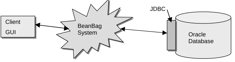
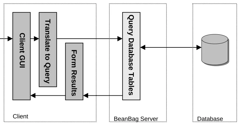
3.3 HIGH LEVEL ARCHITECTURE...51
3.3.1 GUI ...52
3.3.2 The BeanBag System ...52
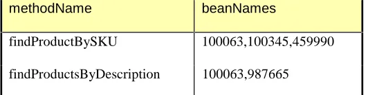
3.3.3 Storage Framework...53
3.4 THE COMPONENT DESCRIPTION...56
3.4.1 Abstracting the Information Content...57
3.4.2 Designing the DTD ...58
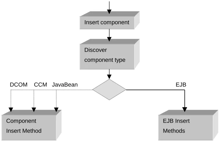
3.5 COMPONENT INSERT AND RETRIEVAL...60
3.5.1 Inserting a component... ...61
3.5.2 Retrieving Components ...62
3.6 SUMMARY...63
4. IMPLEMENTATION...64
4.1 INTRODUCTION...64
4.2 THE COMPONENT FRAMEWORK...64
4.2.1 HomeBase ...64
4.3 THE JAR ARCHIVE...64
4.4 EXTRACTING THE REMOTE INTERFACE FROM THE JAR ARCHIVE...66
4.5 PROCESSING THE XML ...67
4.5.1 Choice of XML Parser...67
4.6 CHOICE OF DATABASE...68
4.6.1 Creating Sequences in Oracle...68
4.6.2 Use of the Oracle LONG RAW datatype...69
4.6.3 Working around the Oracle Open Cursors Exceptions...71
4.6.4 Achieving integrity in the database tables ...71
4.7.1 Searching for an exact Interface match ... 73
4.8 JDBC DRIVERS... 74
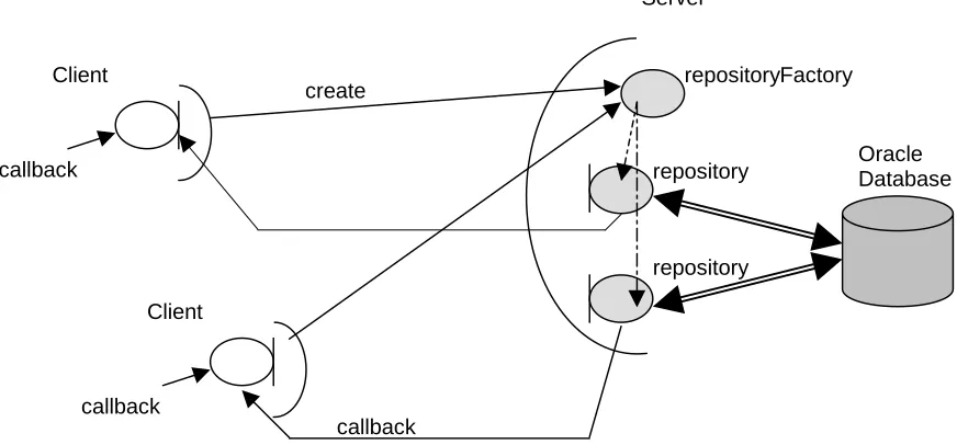
4.9 THE CORBA ARCHITECTURE... 74
4.9.1 Introduction to the CORBA Objects ... 75
4.9.2 CORBA Callbacks ... 75
4.10 THE GUI... 76
4.11 SUMMARY... 76
5. EVALUATION AND CONCLUSION ... 77
5.1 INTRODUCTION... 77
5.2 EVALUATION OF MODULES... 77
5.2.1 The Storage Framework ... 77
5.2.2 The Component Description ... 78
5.2.3 The Query System ... 79
5.2.4 Queries Implemented ... 79
5.2.5 Evaluation of Exact Interface Matching ... 79
5.3 CONCLUSIONS... 80
5.3.1 Achievements ... 80
5.4 FUTURE DEVELOPMENTS... 81
5.4.1 BeanBag as an EJB Component ... 81
5.4.2 Extending BeanBag as a CORBA Component Repository... 83
5.4.3 Using OCL to describe the pre- and post- conditions ... 84
5.4.4 Searching on the Documentation... 85
5.4.5 The Oracle XML SQL Utility for Java ... 85
5.4.6 Implementing an XML Properties Editor ... 87
5.5 SUMMARY... 87
6. BIBLIOGRAPHY ... 88
7. APPENDIX... 92
7.1 APPENDIX A: SCREEN SHOTS... 92
7.2 APPENDIX B: THE BEANBAG IDL ... 96
FIGURE 2-1 EJB ARCHITECTURE... 12
FIGURE 2-2 THE CORBA COMPONENT MODEL... 19
FIGURE 2-3 BINARY REPRESENTATION OF A COM INTERFACE [SZY98]... 25
FIGURE 2-4 USING BEHAVIOURAL ELEMENTS TO DENOTE THE INTERFACE OF A COMPONENT [KIN98] ... 33
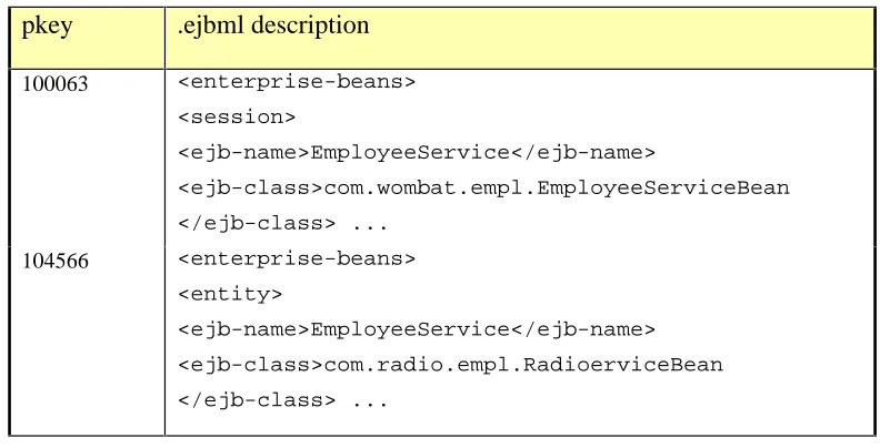
FIGURE 3-1 AN EXAMPLE OF EJB REFERENCES IN A DEPLOYMENT DESCRIPTOR... 51
FIGURE 3-2 THE BEANBAG HIGH LEVEL ARCHITECTURE... 51
FIGURE 3-3 METHODS2BEANS TABLE... 54
FIGURE 3-4 EXTENSIBLE PROPERTIES TABLE... 55
FIGURE 3-5 DESCRIPTIONS TABLE... 55
FIGURE 3-6 HIGH LEVEL MODEL OF THE COMPONENT INSERT... 61
FIGURE 3-7 HIGH LEVEL VIEW OF THE INSERT PROCESS... 62
FIGURE 3-8 HIGH LEVEL VIEW OF THE RETRIEVAL PROCESS... 62
FIGURE 4-1 THE CORBA ARCHITECTURE... 75
FIGURE 5-1 DESIGN FOR BEANBAG AS AN EJB COMPONENT... 82
FIGURE 7-1 RETRIEVING THE REMOTE INTERFACE OF A COMPONENT... 92
FIGURE 7-2 MATCHING THE INTERFACE OF A COMPONENT WITH ONE IN THE DATABASE... 93
FIGURE 7-3 THE METHODS2BEANS INDEXED TABLE... 94
1.
Introduction
1.1
Motivation
Anything less than complete commitment will doom component-based development to
be yet another failed software engineering panacea [Kie98].
With the growing interest in software components in the software industry, ways of
storing and retrieving relevant components is becoming increasingly important.
Retrieval methods are crucial for reuse. As libraries of components grow in size,
traditional information retrieval methods will not provide adequate precision and recall.
Procedures are needed for the effective description of components and their roles if they
are to achieve the promise of reuse. Describing syntax alone, as IDL does is not
sufficient for many applications. What is required is a way of describing both the syntax
and the semantics of components in a language independent way. These descriptions
could be stored and queried by interested parties.
1.2
Proposed Solution
The objective of this thesis was to examine ways of storing, describing and querying
components. The storage framework was designed with efficient retrieval in mind. The
component description had to be component independent and extensible, and the
querying facility had to provide flexibility.
To achieve these requirements the implementation of BeanBag went through a series of
phases. The first was to choose a component framework to work with and to examine
what information about a component was available already. Next, methods were
semantic information a developer may need in a description. When the description was
complete the storage framework was designed to provide efficient retrieval of
descriptions and a module for matching components was implemented. Finally the
system was implemented as a CORBA Server.
1.3
Achievements
The main aim of this thesis was to investigate an extensible way of describing
components. This requirement was achieved and in addition the descriptions are also
component independent. The storage framework was designed in such away as to
achieve efficient retrieval of components. The requirement of transparent insertion of
components was achieved by the BeanBag system automatically extracting any data that
was already available, generating extra data from the component and storing it in the
database.
1.4
Roadmap
The chapter that follows describes the motivations and advantages behind component
software. Also described are the component frameworks available and the current
methods of describing what components provide. Chapter 3 outlines the design steps
behind the BeanBag system and Chapter 4 outlines the implementation route and
technologies used. Chapter 5 is an evaluation of the thesis and contains concluding
remarks about the work and the directions that it could take in the future. The final
chapters contain the Appendix.
1.5
Summary
In this chapter, the problem statement was outlined, as were the requirements of the
BeanBag system. The steps taken to arrive at a system that fulfilled these requirements
2.
Literature Survey
2.1
Introduction
In this section the motivation behind the current interest in component technology is
discussed. The technologies and methodologies currently available for describing and
constructing components are investigated. Areas that are examined are Component
Frameworks, Component Description Languages, XML and XML query languages. It is
necessary to look at what technologies are available and what they offer, before
designing the BeanBag system.
2.2
Software Component Motivation
Components composed of other components allow thinking about problems at the
appropriate level of abstraction. Without this, we wind up thinking about individual
transistors instead of chips and boards [Chap97].
Component based development changes the software development process to be more
industrial like. Developers buy pre-built components and assemble them to their own
requirements. Speed of delivery improves, as does the quality and quantity of systems
developed. If a large part of a software project can be fulfilled using pre-existing
components, then skill sets will reduce. Component technology is often likened to that
of computer hardware design, where a set of pre-built components exist such as
motherboards and hard drives, and these are assembled to produce PCs. Redesigning
and rebuilding these hardware components would be expensive and time-consuming.
Object-Oriented technology has fallen short of its promise of reuse, hence the
emergence of components. If developers can buy pre-tested software components off
the shelf to build their own applications, the software development cycle time will be
significantly reduced. With the diffusion of components, complex systems will yield to
modular components.
Most software projects result in software being bought in or built in-house. Each
direction brings advantages and disadvantages. Software that is built in house is
generally expensive, with customer requirements constantly changing and the
development time being long. The resulting system may not interoperate with future
systems but only with those already in-house. However, the system can be extended and
re-adapted. When buying in software, the solution generally does not fit perfectly,
however it is probably a cheaper solution in the long run, if the manufacturer stays
around long enough to support the system. Component software attempts to find a
compromise between these two dilemmas. A system can be assembled from pre-created
components, but the application developer has scope for customization. Because the
system is modularized, upgrades can happen seamlessly when individual component
upgrades are released.
For system developers, short development times and transparent upgrades are
tremendous gains. If developers are going to buy a software component over developing
their own, the component must have significant advantages. Technical superiority, cost,
and support contract may all influence the customer. Components will have to appeal to
the market if they are to succeed where class libraries have failed.
2.2.1 The Benefits of Components
The technical component market is exploding, during the next five years leading
application development organizations will move from building applications from
In the previous section the motivation behind choosing components was discussed.
Component-based development also brings these advantages when designing
applications. Component-based development:
q can produce applications quickly
q can result in higher quality and more reliable software. When third-party
components are used, these have already been tested. Even though the application in
its entirety must be tested, using components results in higher quality applications.
q lets developers focus more on business problems. Programmers do not have to
worry about low-level programming details, such as database access and security.
q can be cheaper than traditional development. It can take less time and can save
money
q allows easy mixing and matching of languages and development environments.
Components written in one language can be used by another component of a
different language, even on another machine. Because components provide a
standard packaging model this transparency is possible.
q offers the best of both alternatives in the build V’s buy decision. Components
can be purchased and combined into a customized solution.
2.3
What are Software Components?
Software components are binary units of independent production, acquisition and
A software component is a unit of composition with contractually specified interfaces
and explicit context dependencies only. A software component can be deployed
independently and is subject to composition by third parties [Muh96].
Many applications already plug-and-play components. Netscape Communicator allows
the installation of new components such as Apple’s QuickTime or Macromedia’s
Shockwave. These components come from different vendors and can be deployed in
another application. In this case, the duplication of effort for Netscape would not have
been worthwhile and so components bring considerable advantages. Objects are not
geared for a plug-and-play architecture. If a developer is to use a new set of class
libraries, certain programming experience is required. In general it will only be
application programmers that will know how to lever the use of the class libraries. They
are not user-friendly or easy to integrate into applications. Components exist as at a
different level of abstraction. Component plug-ins are easy to install and provide
configuration at a higher level. The customer should not be interested in how the
internals of a component actually work or how it is written, but they should be able to
assemble components to provide a system tailored to their needs.
Many definitions of components exist, two are included above. The important points to
take from these definitions are that components exist independently but can be
assembled into a functioning system. They expose interfaces that are implemented
internally, and it is through these interfaces that other components interact with them.
2.3.1 Components versus Other Kinds of Reuse
The oldest types of components that we use are procedural libraries. They are
independent and in binary form and can be reused by other independent applications.
Functions, classes or modules can form components if they are independent and in
binary form. Components are generally easier to use than procedural libraries, because
often they allow the developer to assemble them visually. Components have better
used allows the programmer to access functionality in a consistent way and also on
remote machines.
Another popular form of reuse are class libraries, libraries of objects. These have
become the foundation for reuse in C++ and Smalltalk. However, to use a class library
effectively, a certain understanding of how the pieces of the library fit together is
required. Sometimes the libraries can be complex. Using components makes this
process easier, as the developer can often use a visual tool to place the component
where it is needed.
Components allow cross-language reuse. Components written in C++ can be used with
components written in Visual Basic or PowerBuilder. If the developer uses class
libraries, the application must be written in the same language as the class library itself.
C++ makes it easy to reuse source code, but it is not easy to create reusable binary
components. Most C++ libraries are shipped in source form, and not in compiled form.
The source code is often required to discover how to inherit from an object. Sometimes
the libraries are even modified and compiled into a private build of the library.
Components are distributed in executable format, the source is not required. In this
way, vendors do not have to divulge their source code. If the component is deployed
internally in an organisation, the absence of source code can have the advantage of the
component not being changed and its business rules are enforced.
As both components and objects are described in common terms the differences
between them can seem hazy. [Szy98] outlines what the differences and similarities are.
A component exists as its own entity and is separate from its environment. Components
make their services available to other components through interfaces. The
implementation of the component is hidden and only available through well-defined
interfaces. A component can provide many different interfaces each one providing a
assembly language or could contain procedures. Mutable state is assigned to component
through resources. Because the resources are separate from the component itself,
changing them does not require the recompilation of the component itself.
2.4
Component Frameworks
Choosing a component model is a critical decision. This choice determines which pool
of components you’ll be able to select from, what tools you can use to assemble
applications using components, and how you’ll create your own components [Chap97].
In the previous section, common features of software components were outlined. The
design of BeanBag takes into consideration the component frameworks that are
currently available. In order to construct a generic design for all components, it is
necessary to understand component architectures and to be aware of the differences
between existing component frameworks. This section outlines the architectures of the
most common component frameworks.
A component framework is a set of interfaces and rules of interaction that govern how
components ‘plugged into’ a framework may interact [Szy98]. Today there are three
major forces in the component framework arena:
• The OMG's CORBA Components (CCM)
• Sun’s Enterprise Java Beans (EJBs)
• Microsoft’s COM.
For effective component assembly, components must be able to interoperate. Obviously
without interoperability the component market will be fragmented and less successful.
Before Sun’s EJB Specification is discussed, it is worthwhile mentioning the
component standard that preceded it, namely JavaBeans.
2.4.1 Java Beans
JavaBeans is a portable platform-independent component model written in the Java
programming language. Developers take advantage of the platform independence of
Java and write reusable components once and run them anywhere.
Mike Day defines beans as objects or components created with a set of characteristics
to do their own specific job [URL7]. They have the ability to take on other
characteristics from the container on the server in which they currently reside. This
enables a bean to behave differently, depending on the specific job and environment
where you place it.
A JavaBean is a component that has interfaces or properties associated with it. It can be
interrogated by and integrated with other beans that were developed by different parties
at different times. A JavaBean is different from other objects in that it has a properties
interface. This interface can be read by certain tools as it describes what the component
does. With this information the JavaBean can be hooked up with other beans and
plugged into other environments.
JavaBeans, in contrast to Enterprise Java Beans are generally visible at runtime. The
visual component can be a button, a list box or a graphic, but the component does not
Individual beans will behave differently, but typical unifying features that distinguish a
bean are:
q Introspection - this enables a builder tool to analyze how a Bean works
q Customization enables a developer, using an application builder tool to customize
the appearance and behaviour of a Bean
q Events enable Beans to communicate and connect together
q Properties enable developers to customize Beans and program with them
q Persistence enables developers to customize Beans in an application builder, and
then retrieve those Beans with customized features intact for future use.
More information on JavaBeans can be found at the JavaSoft JavaBeans Website
[URL5].
2.4.2 Enterprise Java Beans (EJB)
Enterprise JavaBeans take JavaBeans to the next level, that being, to server-based
components. The Enterprise Java Beans API allows developers to build large-scale
business applications as reusable server components.
2.4.2.1 EJB1.0
The first Enterprise JavaBean (EJB) Specification, Version 1.0, from JavaSoft, was
released in March 1998. It defined an API for the development, deployment and
management of server side components. The original JavaBeans specification described
the standard behavior of Java components that primarily ran on the client side. Over 50
products have already been developed to support EJB1.0. Companies such as Oracle,
Borland, Symantec, IBM and IONA have announced and/or delivered products that
2.4.2.2 EJB1.1
The EJB1.1 specification is now available to the public. The main changes from EJB1.0
are:
• Mandatory support for entity beans
• Enhanced deployment descriptors which are formatted in XML, rather than being
serialized
• Java2 security replaces Java1.1 security
EJB1.1 is available from Sun, and can be downloaded from [EJB1.1].
EJB 2.0 has a due date of late 2000, and future specifications will look at issues of
connecting legacy data, integrating messaging systems and representing bean
relationships and inheritance.
Previously, developing multi-tier servers was a complex task, where developers had to
deal with issues of concurrency, transactions, security and scalability, and had to
manage threads, memory and network connections. EJB aims to make the development
of server side components easier, by decoupling application semantics from
infrastructure issues. However EJB is simply a model and vendors provide EJB
solutions.
Enterprise JavaBeans, unlike JavaBeans are generally non-visual and designed to run on
a server, and to be invoked by clients. An EJB could be built out of non-visual
JavaBeans.
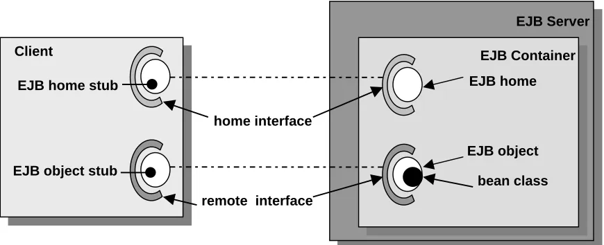
Figure 2.1 illustrates the architecture of EJB with the EJB home and EJB object
implementing the home interface and remote interface respectively. The bean class is
Figure 2-1 EJB Architecture
2.4.2.3 The EJB Client
The writer of an EJB cannot assume what the client will be or on which platform it will
be running or on which machine. The EJB client could be a servlet, a client on
someone’s desktop or could be another EJB. The client could be written in any
language, perhaps Java or C++. If the client is written in Java then the client will
communicate with the EJB by using Remote Method Invocation (RMI) API. If the
client is a non-Java client then it will communicate with the EJB using CORBA
communication protocols such as IIOP.
Once the client has the name of the Enterprise JavaBean that it wishes to communicate
with, it can create a communication channel with the EJB through a network directory
service. Firstly the client receives a reference, like a proxy to the EJBHome object for
the bean. By utilising this reference, the client can retrieve a reference to the EJBObject
for that bean, and consequently can access the remote EJB’s services.
Client
EJB Server
EJB home
EJB object
bean class home interface
remote interface EJB home stub
EJB object stub
2.4.2.4 The EJB Component
An EJB Component is an Enterprise JavaBean. It is a component like a JavaBean,
written in Java by a developer that implements some business logic. Components live
inside a container, and many component instances can exist in a container.
2.4.2.5 The EJB Container
The EJB component model provides an environment in which server side components,
Enterprise Java Beans can be deployed. This environment (the container) provides
transactional capabilities, security and management to the component. Developers
create components that inherit the enterprise attributes from the container. The
component interacts with the container and takes advantage of its transactional or
security features without being aware of how they are implemented by the container.
The EJB container manages the state of the object. An object can have persistent state
or transient state. Components can be deployed in another vendor’s EJB container and
still work, without recompilation, providing it complies with the EJB specification.
2.4.2.6 The EJB Object
On the server side, the EJB object implements the remote interface of the bean. This
distributed object is generated automatically by the EJB vendor and by the information
provided by the deployment descriptor. The EJB object works with the EJB container to
apply transactions, security and other operations to the bean at runtime.
When a client calls a method on an EJB object, the EJB object communicates with the
EJB container and requests that the same method be called with the same parameters on
2.4.2.7 The EJB Home Object
The EJB home object is also generated by the EJB vendor when an EJB is installed in a
container. This object is involved with the bean’s life-cycle, and is responsible for the
location, creation and removal of the Enterprise JavaBean.
2.4.2.8 The EJB Server
EJB components reside in an EJB container when they are deployed. The EJB Server
must implement the EJB container. Any server that can host an EJB container and
provide it with the services that it requires, can be an EJB Server. An EJB Server
provides lower-level services such as network connectivity to the component.
2.4.2.9 EJB Design Patterns
There are two types of Enterprise JavaBeans that can be created, the Session Bean and
the Entity Bean. This is how they differ:
Session Beans
q are non-persistent objects that implement some business logic
q are associated with a single client
q do not survive server crashes
q manage information relating to the conversation between the client and server
q are divided into two types
q Stateless Beans do not store any information relating to the client between calls
q Stateful Beans store information between calls from a client. Values and state
Entity Beans
An entity bean maps a Java class to a data source. This source could be a row in a
database or an entire table. Each entity bean has a primary key associated with it that
identifies the data within [URL21].
Entity Beans:
q are persistent objects, which represent an object view of entities in persistent
storage
q are associated with database transactions
q may provide data to multiple clients, concurrently
q survive server crashes, because the data that the bean represents is persistent.
q Represent and manipulate persistent application domain data
q Entity Beans are also divided into two classes
q Container-managed is the simplest form of entity bean. Using container
managed beans means that developers do not need to worry about how the
persistent data is stored or retrieved. The container manages the database calls.
q Bean-managed is used by developers who need more control on how the data is
stored or retrieved from the database. The database calls are made from the bean
itself and are hard coded in. The disadvantage is that the bean is more tightly
coupled with the underlying architecture.
EJB Components are deployed using the Java Beans packaging format (JAR). Server
components can be deployed in any vendor’s EJB implementation because the business
logic of server components is not tied to the implementation details of a particular
2.4.2.10 Interfaces
An EJB’s provided methods are specified by the remote interface. The EJB object
implements the remote interface of the EJB component. In order for the client to be able
to create objects on the server, the home interface is used. The home interface is a
contract between an EJB component class and its container, which defines construction,
destruction and lookup of EJB instances [URL6]. Each EJB component has a home
interface for this purpose.
2.4.3 The CORBA Components Model (CCM)
The CORBA Component Model (CCM) was approved through a vote by the ORB Task
Force at the end of August 1999. CCM is the final piece needed to complete the
CORBA 3.0 specification, which is a framework for building, assembling and
deploying plug-and-play CORBA objects.
The RFP submitted to the OMG was constructed by an influential group of distributed
middleware vendors: IONA, BEA Systems, DSTC, Expersoft, IBM, Inprise, Oracle,
Rogue Wave and Unisys. As Sun are responsible for the Enterprise JavaBean
specification, they cooperated in the submission.
CCM is essentially a language-independent extension of EJB
[URL11]
The problem that many organisations have with EJB, is that it only supports Java. Many
organisations have software written in other languages and so EJB is not suited to their
environment. CCM supports EJB components as well as components developed in
[Hub99] describes the differences between CORBA Components and Enterprise Java
Beans, and examines why the OMG are developing their own component standard
instead of endorsing the EJB directly. Some of these points are listed here:
1. The CCM designers assert that ‘the JavaBeans model is inappropriate for
server-side development’. This may be the case in some ‘demanding situations’ but this
does not mean that EJBs are generally inadequate for server-side development.
2. The EJB specification deviates from the OMG charter in the following areas:
q OMG technologies must strive to integrate multiple language specifications
(e.g. Java and C++)
q OMG standards are approved according to the OMG’s open technology
specification process
q Technologies must be developed in compliance with the OMG’s Object
Management Architecture (OMA) and should respect styles such as IDL, IIOP
and the CORBA Services.
q OMG technologies must provide an explicit metamodel based on the standard
Metaobject Facility (MOF)
The CORBA Components model like EJB, is related to server-side CORBA
Components. CORBA Components extend the core CORBA object model, and provide
a higher level of abstraction, thus greatly simplifying CORBA programming. CCM
The CORBA Component model provides:
Extensions to IDL that will support components and the relations between them
CIDL, a mechanism for automatic code generation for defining servant
implementations
Extensions to the CORBA core object model
A means to support navigation across multiple interfaces of a CORBA Component
It includes a deployment model using XML, to describe the runtime properties of a
component.
It defines a container model
It introduces the container programming model
Defines policies that provide a simplified version of CORBA Transactions.
Defines policies for servant lifetimes, security and persistence
Defines a mapping to Enterprise JavaBeans so that they can be supported as a
CORBA Component
[CCM99]
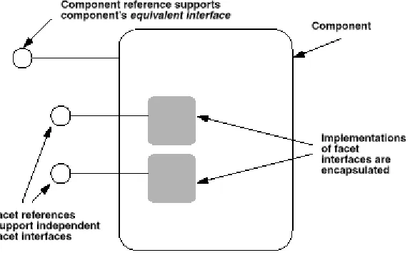
2.4.3.1 The Component Model
Component is a new meta-type in CORBA, it is an extension of the Object meta-type.
A Component can be specified in IDL and stored in the Interface Repository. A
Figure 2-2 The CORBA Component Model
Clients interact with components through surface features called ports. There are five
types of ports:
• Facets - distinct named interfaces provided by the component for client interaction
• Receptacles - named connection points
• Event sources - named connection points that emit events
• Event sinks - named connection points into which events may be pushed
• Attributes - named values exposed through accessor or mutator methods
2.4.3.2 Facets
A component may provide multiple object references, called facets, which are capable
2.4.3.3 Equivalent Interface
This interface makes the component’s surface features visible to the clients. Other
interfaces provided are called facets. Clients can navigate from any facet to the
Equivalent Interface, and can obtain any facet from the component’s Equivalent
Interface.
2.4.3.4 IDL
A component definition in IDL, defines an interface of a component, that supports the
features defined in the component definition body. Component definitions differ from
interface definitions in that they can only support single inheritance.
A component body can contain the following type of port declarations
q Provides - provided interface declaration
q Uses - receptacle declarations
q emits/publishes - event source declarations
q Consumes - event sink declarations
q Attribute - attribute declarations
All these IDL declarations map onto operations in the components equivalent interface.
2.4.3.5 CORBA Components Vs Enterprise JavaBeans
The CORBA Component Model and the Enterprise JavaBean Model are actively
evolving in parallel. Each new release of the specifications retests the leader/follower
relationship. Some of the differences between the two models are detailed in [Hub99].
q CCM uses IIOP as its wiring protocol. EJB is less specific, some EJB based Java
application servers require RMI, and others support IIOP, or both. This lack of
q CCM containers can be implemented in C++ or Java. This is hardly surprising, as
integrating heterogeneous technologies is one if the OMG’s primary goals.
q CCM interfaces are specified in Component-IDL (CIDL). CIDL is an extension of
CORBA IDL. EJB is based on pure Java interface specifications.
q CCM descriptors are specified in XML using DTDs. They are more extensive than
EJB descriptors. EJB uses Deployment Descriptors to configure the Container
properties. The Deployment Descriptor in EJB1.1 is XML based. Most vendors
however have implemented EJB1.0 in which the Deployment Descriptor is itself a
JavaBean and is delivered together with the EJB as a serialized Bean in the JAR
file.
q EJB supports two component abstractions, Session and Entity Beans. CCM adds a
Process component abstraction, which is like a stateful Session Bean in EJB. CCM
Processes will allow more precise control of component lifetime, state management
and identity than is possible with standard EJBs.
q CCM specifies properties and behaviours for managing the installation of
components including managing software dependencies and component assemblies.
EJB is much less complete in this area.
q CCM defines structural and behavioural features for extensive runtime component
q CCM places metadata (information about the component interfaces) in the CORBA
Interface Repository, therefore maintaining language independence. EJB uses Java
language features and EJB Container features to provide similar information.
q CCM defines a metamodel and expresses it in the XML Metadata Interchange
format (XMI)
q CCM uses the CORBA Services (COSS) for Events, Naming, Life Cycle,
Persistence, Security and Transactions. In some cases, CCM defines a subset of the
COSS with some design changes to tighten integration. EJB has adapted subsets of
COSS features in Transactions and Naming. JavaSoft has adapted or redesigned the
other COSS themes, which means they cannot be seen as COSS-compatible subsets.
q CCM defines a bi-directional mapping to EJB. EJB specifies a CORBA mapping
for client communication and intercontainer interoperability. EJB could not address
component model compatibility because CCM did not exist at that time.
2.4.4 COM Components
Microsoft’s component technology has evolved from the non-object oriented Visual
Basic components, to object linking and embedding with OLE and now to COM and
DCOM. COM is a binary standard. This means that it is not concerned with the
languages in which the components are written. Components do not have to be
object-oriented behind their interface.
2.4.4.1 Visual Basic, OLE and ActiveX
Microsoft's first attempt at component technology was Visual Basic controls (VBXs).
word processors, database connectivity and charting. However, VBXs are tightly
coupled to Visual Basic forms, and so OLE controls were introduced (OCXs). OCXs
are COM objects whereas VBXs are not. To qualify as an OLE component, the COM
object has to implement many interfaces. The downside is that small controls have to
carry extra baggage, and so implementing them is less attractive than VBXs.
After OLE controls came ActiveX controls. ActiveX is a new specification. An
ActiveX control need only implement one interface, the IUnknown. The control must
also be implemented in a self-registering server, so that when the server is started, it
registers the classes with the system registry. ActiveX controls have regular COM
interfaces, but also have outgoing interfaces, which are used for a notification
mechanism.
2.4.4.2 COM
The Component Object Model (COM) is a way for software components to
communicate with each other. It is a binary and network standard that allows any two
components to communicate regardless of what machines they are running on (as long
as the machines are connected), what operating systems the machines are running (as
long as it supports COM) and what language the components are written in. COM also
provides location transparency, in that it does not matter if components are in-process
DLLs, local EXEs or if they are located on another machine.
COM objects are well encapsulated. There is no way to find out how they are
implemented internally. To communicate with a COM object, interfaces are used.
The COM interface is fundamental to COM. The only way to communicate with a
COM object is through an interface. An interface is a contract between the component
and its clients, that defines what functions are available and what the object does when
the functions are called [URL13].
An interface is represented as a pointer to an interface node. The interface node
multiple interfaces. The client never gets a pointer to the class itself, which means that
the back end implementation can be replaced unknown to the client.
COM does not support any form of implementation inheritance. This does not mean
that you cannot reuse COM components. To reuse them, containment and aggregation
are used. When a class is inherited generally only a couple of methods are needed.
Containment means the object required is instantiated, and requests are passed to it.
One object contains another object, conceptually, i.e. one object holds an exclusive
reference to another object. Passing on the requests to the contained object simply
means calling its methods. Containment is completely transparent to the client, and it
will not know that the contained object was invoked to carry out the method. If deep
containment hierarchies occur, they can become a performance overhead, so COM
defines aggregation.
Aggregation means that instead of forwarding requests to an inner object, the inner
object’s interface reference should be given to the client. Calls on this interface are not
intercepted by the outer object, and are passed directly to the inner object, which
eliminates the forwarding overhead that exists in containment. Transparency is
important here also, and the client should be unaware that the interface it uses has been
aggregated from an inner object.
In practice containment is used more often then aggregation. Aggregation is generally
used where there are deeply nested constructions. Aggregation also brings an extra level
of complexity [Szy98].
Every COM object implements the IUnknown interface. The identity of the IUnknown
interface can serve to identify the entire COM object. All interfaces must derive from
IUnknown. IUnknown is the only interface guaranteed to be present. The IUnknown
interface supports the three mandatory methods of any COM interface, namely,
Figure 2-3 Binary representation of a COM interface [Szy98]
Every COM component has a common method called QueryInterface(). Given
one interface, QueryInterface() can be used to obtain a pointer to a different
interface. The method checks whether the given interface is supported by the COM
component and if it is, it returns the corresponding interface reference. Using
QueryInterface() the client can navigate from any provided interface to another.
Interfaces are represented using interface identifiers
Polymorphism in COM is achieved by COM objects supporting a set of interfaces. The
type of a COM object is the set of interface identifiers of the interface it supports. If a
client requires that four interfaces are supported by a COM object, and the COM object
supports these four and four others, then the client’s requirements are satisfied.
QueryInterface() is used to test whether a COM object supports the required
interfaces.
The COM interface and its specifications cannot be changed after they have been
published. The contract is immutable, you cannot add to it, you cannot delete, and you
cannot modify it. You can improve the internal implementation once you still honour
the contract. If the requirements change, you can always write a new contract, as COM
supports multiple interfaces. COM also allows for the inheritance of interfaces, so an
entire interface need not be rewritten. Client
Variable
Interface Node
Op 1
Op 2
2.4.4.3 DCOM
COM supports inter-process communication, but not communication across machines.
DCOM builds on COM to provide communication across process boundaries and
machine boundaries. When communication exists on a single machine, there is no need
to know how data types are represented because the sending process is using the same
representation as the receiving process. When communication is across machine
boundaries, the data representations can be different. Therefore COM creates proxy
objects on the client side and stub objects on the server side. To deal with differences in
data representations across machines, DCOM marshals data into network data
representation (NDR) which is a platform independent format.
2.4.4.4 COM+
COM+ was released by Microsoft in October 1997 and is essentially an extension of the
Microsoft Transaction Server (MTS). MTS provides components with services, such as
transaction processing monitoring, database connection pooling, and multi-user access.
COM+ allows a single threaded object designed for single users to be used by multiple
simultaneous clients. New services have been included for COM objects in COM+ such
as events, asynchronous messaging, dynamic load balancing, and life cycle
management [COM+99].
2.4.5 Commercial Application Servers
Since the CORBA Component RFP became available, vendors such as Fujitsu, IBM,
Inprise, IONA, Oracle and Sun, have stated their commitment to either support and/or
implement the CORBA Component Model. Since [EJB1.1] many vendors have already
implemented Enterprise JavaBeans Application Servers. Examples of commercial
Application Servers are:
• HomeBase from IONA. A beta release of OrbixHome was not available at the time
• BEA WebLogic Enterprise Server, version 4.2 will add support for CORBA Components written in Java or C++. WebLogic Enterprise 5.0, scheduled for end of
1999 will support the Java2 Enterprise Edition platform, which includes EJB1.1.
• Netscape Application Server 4.0 includes EJB1.0 support and support for entity
beans.
• Ejipt 1.2 is an all Java, low cost application server that implements both the
required and optional features of EJB1.0, including entity beans. With a small
footprint of 300K, it can be deployed on a laptop, and supports Java1.1 and 1.2
clients.
2.5
Component Description Languages
A lot has to happen to make software componentization and reuse a reality. One of the
biggest hurdles is the lack of standards that let an application know what a particular
component can be used for [Kin98].
If components are going to live up to the promise of reuse, then standards are needed
for describing what a component does, so that relevant components can be retrieved.
Component Description Languages do exist, and in this section a number of them are
examined to investigate if they can sufficiently describe the semantics of the
components listed in Section 2.4.
2.5.1 IDL
IDL is used to describe the interface of a component. The description is purely syntactic
and does not give us any information about the behavior of the component or how
2.5.2 OCL
In 1996, the OA&D Domain task force at the OMG issued a request for proposals on
Object Analysis and Design. IBM and ObjecTime Limited jointly submitted a proposal
in January 1997. An important aspect of this proposal was the inclusion of the Object
Constraint Language, or OCL[URL4].
The Object Constraint Language (OCL) is part of the Unified Modeling Language from
Version 1.1 onwards. UML includes common constructs for object oriented modeling
such as class models, state machines, use cases and collaboration diagrams. UML is
now the global standard modeling language of the OMG. Therefore OCL is likely to
receive more attention than other normal specification languages such as VDM or Z.
The language is designed to augment class diagrams with additional information that
cannot be represented in UML diagrams. A class diagram does not contain enough
information to make it an unambiguous representation. Additional constraints about
objects in a model are needed, to provide an unambiguous description. These are
typically annotated in natural language. Formal languages have been developed to
describe these special constraints, but they are not user friendly, and typically require a
mathematical background to decipher.
OCL is a formal language that is easy to read. OCL is a modeling language and not a
programming language; therefore it is not possible to write program logic in OCL.
Because it is a modeling language, the implementation details are beyond the scope of
OCL.
OCL can be used for a number of different purposes:
q to specify invariants on classes and types in the class model
q to specify type invariant for stereotypes
q to describe pre- and post- conditions on operations and methods
q to describe guards
q as a navigational language
q to specify constraints on operations:
OCL allows the expression of invariants and pre- and post- conditions that specify the
behavior of a model, without getting involved with implementation details. The next
section describes how BeanBag could use OCL to provide more semantic descriptions
of software components.
2.5.2.1 OCL Invariants
Presenter
self.qualifiedFor->includesAll(self.offering.seminar)
This invariant for a scheduling system says that a presenter must be qualified for all
seminars that he/she is assigned to present. self refers to an instance of a presenter.
2.5.2.2 OCL Preconditions and Postconditions
SeminarSchedulingSystem
MarkAsAbsent(p : Presenter, from, to : Date)
Pre: true
Post: p.offering@pre->forAll(o | o.date >= from and o.date <= to implies o.presenter = Set{})
In this example OCL is used to specify pre- and post- conditions for the method
MarkAsAbsent. In OCL, the value of a property at the start of an operation is denoted
by, propertyName + @ + pre. The post condition in this case marks a presenter as
absent by cancelling his/her presentations within specific dates.
OCL fulfils the requirements for BeanBag as it can be used to describe the semantics of
2.5.3 JBCDL
JBCDL is a component description language based on the Jade Bird Component Model
(JBCOM). JCBOM describes component interfaces. The JBCDL is intended to aid
component composition, component verification and component retrieval [QJHF98].
JCBOM describes a component as comprising of seven parts: template parameters,
provided functions, requirements, members, connections, imported specifications and
implementation. The component definition language was designed with reuse as a
primary aim. The language is easy to understand so developers can quickly judge the
suitability of the component. The syntax of JBCDL relates to the JBCOM and has 6
specification parts, template parameters, provides, requires, contains, connection and
imports. The implementations are described in programming languages. JDBCL is most
suited to describing object-oriented components; hence inheritance is included in the
specification, as most OO languages support this.
2.5.4 KDL
KDL is a Component Description Language developed by Joseph R. Kiniry. The
language is used to describe both the interface and behavior of software components.
The language is an extension of the OMG’s Object Constraint Language (OCL). It is
used to specify the interface and the externally observable side effects of methods.
Expression languages such as Eiffel or OCL use pre- and post- conditions on each
method. KDL allows the specification of interfaces such as IDL interfaces plus it can
also specify semantic relations of components. KDL includes relationship operators,
like those used in UML to denote relations between components (cdlHasA,
cdlContainsA). Also included are ways to specify if components are related under
cdlIsTypeOf and cdlIsKindOf.
From examining the features of these component description languages, OCL is most
suitable as it is has been adopted as a standard by the OMG and it provides the
functionality that we require, i.e. representation of pre- and post- conditions and
There are other ways of describing the semantics of components and providing insights
into the functionality of a component. In the next section modelling languages are
discussed that could be utilised by BeanBag to extract more information from a
component.
2.6
Modelling Languages
The widespread utilization of a specification language, much like a normal computer
language, seems to be inversely proportional to the language’s complexity - i.e., the
simpler the language, the more system builders will use it [Kin98].
Designers need to know more about a component than just its interface. Components
and objects can be described in a formal way, so that there is no ambiguity as to their
function. Modelling languages have been developed for this purpose.
Current system specification methodologies can be divided into two communities, the
informal and formal. Most designers are familiar with UML, which like OOCL and
Cataysis belong to informal methodologies. These methods are not concerned with
system correctness. OOCL can be used to model larger systems such as organisations,
as well as software systems. It adds several diagrams to UML, but fails in the area of
component representation and interaction.
2.6.1 UML
UML is used to informally document the interactions between the user and the system,
and has become popular because its learning curve is manageable by most designers
and because the OMG has adopted it as a modelling language. Plus UML diagrams can
be interpreted easily by customers.
system correctness against a specification, they require a steep learning curve for the
developer.
UML provides mechanisms for extending system specifications [Kin98]:
• Packages: a collection of model elements
• Stereotypes: indicates a usage or semantic extension
• Constraints: a semantic relationship between model elements that specifies
conditions and propositions that are invariant. The conditions are generally
described in a formal language such as Z or OCL.
{message.oclIsTypeOf(SummonRequest) }
{∀ n : • n + n even.`
• Properties and tagged values
• Notes: graphical symbols that contain information, usually textual, or comments
about the model.
UML does allow component diagrams, but it does not have any utilities for describing
the relationships that components can have with each other. It does not document a
component’s inbound and outbound interfaces sufficiently. DESML addressed these
issues, and aims to provide a framework for describing components where UML stops.
2.6.2 DESML
[Kin98] describes DESML as a new set of modelling constructs, which can be used on
top of other modelling languages. DESML aims to describe a component in a formal
way to aid designers, but it also aims to be easy to use and easy to learn. [Kin98]
examines the difficulties in designing a system that would not have a steep learning
curve. DESML is a variant of UML, not an extension, as the UML core meta model
Figure 2-4 Using behavioural elements to denote the interface of a component [Kin98]
In [Kin98] some of the problems of component representation are discussed:
• Core Component Representation
[Kin98] describes the features that are missing in UML, when it comes to describing
components.
1. The Outbound interface: aka the needs interface. There are other elements that the
component needs to operate properly.
2. Properties and Attributes: the properties of components usually have special
semantic values, i.e. the identifier might be a unique number.
4. Dependencies and Associations
• Partial Component Interface Specification
A component depends on a set of other components, but not on all the interfaces of all
these components. UML does not provide a way of describing this.
• Component Associations
Components have associations with other components. The most common associations
are containment and aggregation. These associations are defined using stereotypes and
constraints. However, these definitions are sufficient for the OO world, but components
require more complex associations to be modelled. In [Kin98] a list of possible
associations are defined:
• Standard Local Reference
• Garbage Collector Reference Type
• Guarded Reference
• Weak Reference
• Phantom Reference
• Soft Reference
• Indirect Association
• Renewable Association
• Mobile Association
• Constant Association
• Channel Association
• Event Association
• Method Association
• Reflective Association
• Meta Association
• Semantic Association
• Persistent Association
• Dynamic and Emergent Structures of Components
In [Kin98] a new way of describing networks of components is introduced, that of the
Object Network Diagram. New constructs have been added, such as Agents, which
represent an autonomous thread of control, Types are classifiers of objects, and Kinds
which add semantics to types.
• Tying Knowledge/Semantics to Components
Because there is still room for mis-interpretation in UML, extra semantic information
about a component will become crucial to helping developers find the components that
they require for their system. The new metaclass Kind helps describe if two components
are semantically similar.
If UML or DESML descriptions were available to BeanBag, they could be processed
and the semantic information they provide could be stored persistently. Details about
what other components are required by a component and what its semantic kind is, are
of interest to a developer that is searching for a component
2.7
Component Repositories
BeanBag is intended to be a component repository for various components. There are
many commercial component repositories available that combine a storage mechanism
details about component interoperability, design models and interface specifications.
The next section describes research in the area of component repositories and examines
the features and shortcomings of some commercial repositories.
2.7.1 A Distributed Repository for Object-Oriented Software Components
[OYM] describes the design of a distributed OO repository. The main point to note is
that this repository is distributed among machines, with no central datastore. The
repository is used to store OO software components and the relationships between them
are represented using hypertext. Useful features include multiviews of the components
depending on whether the implementation is public or private.
Difficulties with using this system is that the target language is C++, and the repository
is not designed for storing the components described in Section 2.4. Data about the C++
classes is extracted from the source code, such as class declarations, type information,
class name, interface definition and dependencies. However this requires that the source
code of the software is available, which in real life components, will probably not be
the case. This system was in prototype version at the time of publication of [OYM].
2.7.2 DELOS
[Geor99] describes the development of a semantic repository for the DELOS
environment, which focuses on integrating legacy systems. DELOS is an environment
that supports the development of applications using distributed components that
employs a central repository containing component meta-data about IS systems. The
repository captures knowledge about the company’s business processes, operational
knowledge of legacy systems and IS knowledge of system components. The repository
is based on the Semantic Index System (SIS) which has primitives that represent entity
classes, attributes and relationships. Component behaviour is represented by using a
[Geor99] describes how legacy data can be represented in the repository by using
reverse-engineering rules to obtain semantics about data. Components are divided into
two groups: generic or customised. Generic components may be suitable for reuse in
many applications while customized components are specialised to perform a certain
task.
A user constructs queries about the legacy systems. Internally the queries are converted
from JDBC calls into the native query service that the legacy system supports. The
result is returned to the user. Legacy components are wrapped with DELOS wrappers
that are Java classes that can receive events from DELOS.
This system focuses on IS components. It is worthwhile to see how this system deals
with legacy components. BeanBag must be designed to handle all component types.
The DELOS system divides components into two groups depending on how reusable
they are. BeanBag should also attempt to categorise components in this way.
2.7.3 Softlab’s ENABLER Open Repository
This component repository was designed while considering the heterogeneity of
components. The repository provides a component management system with versioning
control, information sharing across workgroups and release management facilities. It is
an integration framework that spans the desktop, Internet and the network. The
components that are stored are a mix of program code, spreadsheets and forms. The
WhitePaper for Enabler can be viewed at [URL1]. The repository is not specifically
designed for the components that were discussed in Section 2.4.
2.7.4 The Microsoft Repository
Microsoft Repository is used to share software components and store information about
them such as Web pages and design documents. Version 2.0 ships with Visual Basic
a model in the form of Repository classes, interfaces, properties and relationships by
using UML [URL14].
The Microsoft Repository stores the repository data in a relational database, and XML
can be used to exchange data between the tools and the repository.
Investigating other commercial component repositories helps formulate the
requirements for BeanBag. Features such as component classification need to be
included in a component repository. It is also possible to store extra data with the
component, such as its UML design documents and perhaps its source code if it is
available. BeanBag must be designed to enable the storage of the components described
in Section 2.4.
2.8
XML
XML is, essentially, a platform-independent way to structure information
[MR99]
As one of the main requirements of BeanBag is to describe components, XML should
be investigated. This section describes what functionality XML could bring in terms of
describing components.
At the moment, web content is tied to how it is displayed. What XML does, is to
separate the content from the presentation. XML is not a language itself but rather a
way of defining languages, which has many potential applications, such as EDI.
Businesses may choose to interchange data, and XML can put structure on the data
exchanged.
XML (Extensible Markup Language) is a formal specification for expressing the
structure of data. It originates from the World Wide Web Consortium (W3C) and is
structure and presentation in this way, an XML document may have the same content,
but can be presented differently depending on what device is being used to access the
page, e.g. the document will look different on a mobile phone than on a computer
screen.
Just as important is the fact that XML is inherently extensible. This means that
developers can specify their own tag sets. If a tag is created to describe a set of recipes,
and if tags describe the content then it is easier to search for the relevant data. It would
be possible to retrieve the authors names and search in the bodies of recipes, because
the tags describe the data. The XML for part of the recipe could look like this:
<author> Polly Jean Harvey </author>
<recipe_name> Dorset homemade strawberry jam </recipe_name>
XML and HTML are document formats derived from SGML (Standard Generalized
Markup Language). HTML is an application of SGML, whereas XML is a subset of
SGML. XML was designed with the Web in mind, while keeping the benefits of SGML
and removing the complicated parts. HTML is suited best to fast data publishing on the
Web. If the data requires more structure then XML may be used. For high-end highly
structured publishing applications, SGML will continue to be used [URL15].
2.8.1 DTDs
Document Type Definitions (DTDs) are sets of syntax rules for XML tags. They define
what tags are used in a document, what order they should appear in, which tags can
appear nested inside others and what attributes tags have. A DTD is like a schema used
in a database, but DTDs are less restrictive and allow for more variations of data. A
DTD can specify that some fields are optional and that others can occur multiple times.
HTML has its own universal DTD, however some people will need to define their own
An XML file must be well-formed and valid. There are certain XML syntax rules that
need to be applied if a document is said to be a well-formed XML document. For
instance, data must be ended with an end tag or an empty element tag. XML tags are
case-sensitive. HTML contains error-handling code that deals with HTML with missing
end tags and non-matching tags. However, this is not sufficient for XML, which
demands a higher quality.
For an XML document to be well-formed it must follow three basic rules
1. The document starts with an XML declaration <?xml version=”1.0”?>
2. There is a root element in which all others are contained.
3. All elements must be properly nested. No overlapping is allowed.
[URL16]
If a document conforms to a specific DTD, then it is said to be a valid XML document.
XML browsers need only concern themselves with whether an XML document is
well-formed, in order to read it.
XML parsers examine XML code and report forming errors if the XML is not well
formed. A DTD might specify that certain data should be present between two tags. The
tags might be there and matching, and so it passes through the parser, but the data might
not be there. DTDs are used to ensure the correct data is there also. A validating parser
can be used to perform this task.
XML links have more functionality than HTML links. In HTML, links can be made to
the middle of a page only if there is an anchor there already. The linking specification
XL
![Figure 2-3 Binary representation of a COM interface [Szy98]](https://thumb-us.123doks.com/thumbv2/123dok_us/920818.604774/33.595.103.508.110.235/figure-binary-representation-com-interface-szy.webp)
![Figure 2-4 Using behavioural elements to denote the interface of a component [Kin98]](https://thumb-us.123doks.com/thumbv2/123dok_us/920818.604774/41.595.125.504.117.410/figure-using-behavioural-elements-denote-interface-component-kin.webp)