Sharif University of Technology
Scientia IranicaTransactions A: Civil Engineering http://scientiairanica.sharif.edu
Seismic behavior of chevron concentrically braced
frames with weak beams
S.M. Dehghan
, M.A. Najafgholipour, and H. Hooshangi
Faculty of Civil and Environmental Engineering, Shiraz University of Technology, Shiraz, P.O. Box 71557-13876, Iran. Received 4 March 2017; received in revised form 21 January 2018; accepted 14 May 2018
KEYWORDS Chevron braced frame;
Finite element method;
Nonlinear analysis; Response history analysis;
Seismic behavior; Weak beam.
Abstract. Concentrically braced frames provide ductility and imparted seismic energy dissipation through yielding of tension braces and buckling of compression braces. In braced frames with chevron conguration, dierence of actions in tension and buckled brace results in considerable unbalanced force at brace-beam intersection, which is addressed in modern seismic design provisions. In this paper, the role of exural capacity of beam in carrying this unbalanced force and consequently, seismic behavior of braced frame were investigated by nite element analysis. Two-story and four-story chevron braced frames were modeled in ABAQUS software and studied by means of nonlinear cyclic pushover and nonlinear response history analysis methods. Results showed that inadequate exural strength of the beams reduced lateral stiness and strength of braced frame signicantly as lateral drift increased. Therefore, concentration of lateral deformation on one story might cause formation of soft and weak story. Furthermore, seismic behaviors of chevron braced frame and two-story X braced frames were compared.
© 2020 Sharif University of Technology. All rights reserved.
1. Introduction
Lateral force resistance can be provided by dierent structural systems. Steel Concentrically Braced Frame (CBF) is a lateral force resisting system which serves as a vertical truss for lateral loads such as earthquake and wind. Since in CBF, centerline of brace passes through intersection of beam and column centerline, initially lateral loads are mainly supported by axial tension or compression forces in members. The CBF is a common Seismic Force Resisting System (SFRS) with high lateral stiness, ease of construction, and low fabrication cost. Many buildings with CBF system are located in high seismic risk regions, such as many
*. Corresponding author. Tel.: +98 71 37277656
E-mail addresses: [email protected] (S.M. Dehghan); [email protected] (M.A. Najafgholipour). doi: 10.24200/sci.2018.20494
highly populated cities of Iran, e.g. Tehran, Shiraz, Tabriz, and Mashhad.
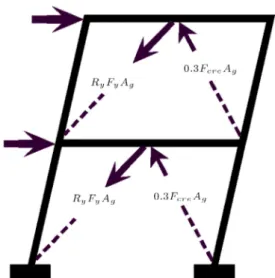
In the linear behavior range, seismic force is resisted through truss action, while in the nonlinear behavior stage, earthquake energy is dissipated by yielding of tension braces and buckling of compression braces. Therefore, to provide sucient ductility, braces act as fuses in the CBFs where columns, beams, and connections should remain elastic. Dierent patterns of bracing, including X, V, and two-story X, can be employed for the CBFs. For providing architectural access, such as doors and windows, chevron braces with V and inverted-V congurations are frequently utilized. As shown in Figure 1, when tension brace yields and compression brace buckles, connecting beam of the V and inverted-V bracing undergoes large vertical and horizontal unbalanced forces in the nonlinear range, which is not captured in the conventional linear anal-ysis. If the beam does not have sucient strength to support this unbalanced force, its nonlinear behavior
Figure 1. Unbalanced force in the connecting beam of inverted-V SCBF.
Figure 2. Computing unbalanced force in the inverted-V SCBF as per AISC 341-10.
may alter seismic performance of the chevron CBF system.
Seismic design provisions of chevron CBF [1,2] prescribe that the beam in V or inverted-V CBF should have sucient strength to support the unbalanced force and gravity loads as shown in Figure 2. The unbalanced force for Special Concentrically Braced Frame (SCBF) can be computed according to Figure 2 as the dierence between the expected brace strength in tension (Pet)
and expected compression strength (Pec) or expected
post buckling strength (= 0:3Pec). It should be noted
that the most critical case of this capacity design procedure should be considered for the beam design.
The expected brace strengths in tension and com-pression are determined by means of Eqs. (1) and (2):
Pet= RyFyAg; (1)
Pec= 1:14FcreAg; (2)
where Ry, Fy, Ag, and Fcre are respectively ratio of
the expected yield stress to the specied minimum
V SCBF systems is investigated through nonlinear cyclic pushover analysis and nonlinear response history analysis. Three types of beam are considered, namely strong beam, weak beam, and very weak beam. Strong beam has sucient strength following seismic design provisions, while exural strength of weak and very weak beams is insucient for supporting the unbal-anced force of the braces. Eect of beam exural capacity on seismic performance is evaluated through story stiness, story lateral strength, beam vertical deformation, and inter-story drift ratio. Furthermore, inuence of bracing conguration (two-story X versus inverted-V) is investigated to mitigate the adverse eect of weak beam.
Several analytical and experimental investigations have been conducted into lateral behavior and seismic performance of chevron braced frames. The analytical studies are outlined as follows. Dierent design ap-proaches to multi-story chevron brace were examined by Robert and Tremblay [3] and height limitations were proposed for each design procedure. In addition, a detailed study of a building with chevron brace, which suered major damage in 1994 Northridge earth-quake, was performed by means of response spectrum, nonlinear static (pushover), and nonlinear response history analysis methods [4]. Another analytical study focused on evaluating seismic behavior of conventional CBF and modeling special CBF [5]. In an analyti-cal study, Kim and Choi [6] assessed over-strength, ductility, and response modication factor of special CBF and ordinary CBF frame with various numbers of story and span length through pushover and nonlinear incremental dynamic analysis. Furthermore, design of chevron braced frame according to Eurocode was evaluated and a new method was proposed to estimate strength of chevron brace, which was employed for enhanced design of chevron CBF [7]. Dicleli and Mehta [8] compared seismic performances of chevron braced frame with and without damper subjected to near-fault ground motion by nonlinear response history analysis. They also developed a nonlinear structural model to simulate hysteretic load deection of steel box brace in ADINA software, which was applied to evaluating the structural performance of single-story chevron braces [9]. Low-ductility chevron braced frames were also studied by incremented dynamic anal-ysis method [10]. Giugliano et al. [11] evaluated seismic performance and reliability of CBFs designed according to traditional and innovative design strategies. Some other researchers investigated overall behavior and
over-strength factor of a chevron brace with weak beam under lateral loads [12,13]. An improved model was developed and validated using a large number of tests by Hsiao et al. [14], which was applied in accordance with FEMA P695 methodology to evaluate seismic performance of dierent braced frames [15]. Lai and Mahin [16] sought to modify yielding beams in braced frames using a strong-back system and to promote uniform story drift over the height of struc-ture. D'Aniello et al. [17] investigated the inuence of beam exural stiness on the seismic response of chevron CBFs and showed that besides strength, it had a key role in assuring ductile behavior of CBF. Furthermore, Asghari and Azimi [18] studied ductility reduction factor and response modication factor of CBFs with dierent story numbers and bracing types including chevron bracing. In a comprehensive study, Kazemzadeh Azad et al. [19] evaluated the design philosophies and provisions used in the AISC 341 and EC8 for CBF systems with dierent congurations in detail. They concluded that AISC 341 provisions would lead to relatively stronger and stier beams in CBF than EC8 requirements would.
Major ndings of experimental studies on chevron CBF are summarized here. Fukuta et al. [20] conducted a test on half-scale three-story inverted-V braced frames. They concluded that post-buckling behavior of the brace and the interaction between the brace and the beam mainly aected the total seismic behavior of the frame. In another experimental study, Bubela et al. [21] examined incorporating vertical slot-ted connection in steel chevron braced frame to prevent vertical load transfer to beam through full-scale quasi-static cyclic tests on two specimens. Dynamic response of steel CBF with chevron arrangement and elliptical fold line in gusset plate connection was investigated through a test on large-scale shaking table [22]. In this study, excellent behavior of connection was observed and yielding in the middle of the beam did occur as predicted in monotonic analysis. However, non-seismic CBFs with low exural strength beam in chevron conguration were examined by Sen et al. [23{25]. Full-scale two-story braced frame with weak beam tested in this research is employed for verication of the numerical simulation in this study.
2. Numerical model and verication
In this section, details of the full-scale test on two-story chevron braced frame with weak beam are presented. The test is used for verication of the numerical simulation as well as the procedure of the analytical model.
2.1. Details of the tested chevron CBF
Sen et al. in 2013 conducted tests on two full-scale
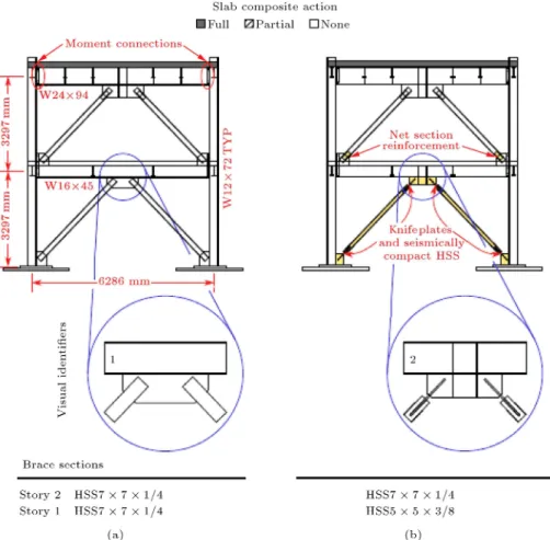
two-story concentrically inverted-V chevron braces in National Research Center of Taiwan [23{25]. Both specimens with low ductility detail were categorized as ordinary CBF based on seismic provisions of AISC 341-10 [1]. As shown in Figure 3, frames had weak beam in the rst story and strong beam in the second story with regard to the unbalanced force of the braces.
In one frame (Figure 3(a)), brace gusset plate without fold line restricted free rotation of the brace to gusset connection, while in the other frame (Fig-ure 3(b)), the fold line provided proper detail. Both frames had similar sections. Upper slab with thickness of 200 mm had composite action with steel beam, but lower slab with thickness of 150 mm was connected to the beam only in few points. Cyclic loading with predened lateral displacement as plotted in Figure 4 was applied to the upper level by three 980 kN capacity actuators. Figure 5 shows photos of the test frame and post-buckling condition of the compression brace. 2.2. Numerical modeling procedure
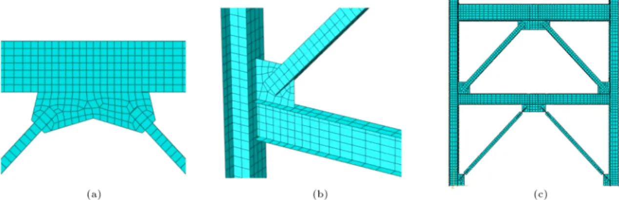
For verication of the numerical modeling, the two-story frame in Figure 3(b) was simulated by ABAQUS software and numerical results were compared with the test results. Since the aim of this study was evaluating the eect of exural strength of connecting beam on chevron CBF, inuence of brace gusset plate detail was not further studied. For numerical simula-tion of steel braced frame response, ABAQUS v.6.14-2 nite element software was employed. Nonlinear behavior of steel material was considered through elastoplastic stress-strain relationship with isotropic strain-hardening eect, as depicted in Figure 6. Yield and ultimate strengths of steel were reported 300 MPa and 400 MPa, respectively. Strain-hardening stiness was 3% the initial stiness of E = 200 GPa. All of the beams, columns, bracings, and connections were modeled by means of linear quadrilateral shell elements at mid-section of the plate. For buckling and post-buckling behaviors of the bracing, as shown in Figure 7, the initial imperfection corresponding to buckling mode of the brace with mid-span out-of-crookedness of 1/1000 the brace length was used. To simplify modeling, eect of concrete slab was ignored. Figure 8 presents geometry of the chevron braced frame model including mid-beam and corner gusset plate. The two-story CBF model contains 4075 nodes and 3850 linear quadrilateral and linear triangular shell elements. 2.3. Comparing test and model results
The deformed shape of the simulated two-story test frame is presented in Figure 9. Figure 10 compares results of the test and numerical models in ABAQUS, showing that the numerical simulation results ade-quately comply with the experimental results.
Figure 3. Two-story CBF with inverted-V brace with weak beam in the rst story: (a) Without fold-line detail and (b) with fold-line detail [25].
Figure 4. History of the frame drift ratio in the cyclic load test program.
model results for the maximum base shear at dierent ratios. It is clear that the numerical model can predict lateral load carrying behavior of the chevron CBF with weak beam in the rst story. Thus, in the current study, similar simulating approach was employed for further investigation into the seismic behavior of this system.
3. Model details
For evaluating weak beam eect on seismic behavior
Figure 5. Two-story CBF with inverted-V brace with weak beam in the rst story: (a) View of the test frame and (b) buckled compression brace [25].
of the CBF with inverted-V bracing conguration, the two-story and four-story frames presented in Figure 11 were studied. Analytical evaluation was performed through nonlinear cyclic pushover analysis and nonlin-ear response history analysis procedures.
3.1. Model building
Figure 6. Stress-strain behavior of steel material.
Figure 7. Initial imperfection of bracing with regard to its buckling mode with magnication factor of 5.
of the model oce building with two braced frames on each perimeter axis in both directions. Two- and four-story braced frames with equal heights of 3.2 m were designed according to AISC 360-10 [26] and AISC 341-10 [1] provisions as Special Concentrically Braced Frames (SCBF). The typical beam, column, and brace sections are tabulated in Table 2. Uniform dead load and live load were considered as 5 kN/m2
and 2.5 kN/m2, respectively. Material properties in
Figure 9. Simulated two-story CBF inverted-V chevron brace with weak beam in the rst story: (a) Out-of-plane buckling of the rst-story brace and (b) deformed shape. Table 1. Relative errors in the test and model results for the maximum base shear at dierent drifts.
Frame drift ratio (%)
Base shear (kN)
Error (%) Test Model
0.8 1759 1602 9
0.9 1780 1634 8
1 1811 1655 9
1.3 1822 1650 9
First story drift ratio (%)
Base shear (kN)
Error (%) Test Model
1.2 1745 1613 8
1.4 1767 1635 7
1.7 1801 1669 7
2.1 1812 1657 9
model building were similar to those of the tested braced frames in Section 2.2. The brace sections were chosen to meet strength and drift requirements of the SFRS. The column sections were also selected to satisfy capacity design requirements of AISC 341-10. The Demand Capacity Ratios (DCRs) of beam sections for
Figure 8. Geometry of nite element model of the test frame: (a) Mid-beam gusset plate, (b) corner gusset plate, and (c) 3D view.
Figure 10. Comparison between the experiment results [23{25] and numerical simulation results in ABAQUS: (a) Base shear-frame drift, (b) shear drift of the rst story, (c) shear drift of the second story, and (d) vertical displacement of the beam drift of the rst story.
Figure 11. Details of model building: (a) Typical plan, (b) elevation of two-story chevron CBF, and (c) four-story chevron CBF.
Table 2. Braced frame sections.
Column of two-story CBF Column of four-story CBF Brace Beam Type of beam 1st and 2nd 1st and 2nd 3rd and 4th
W12 72 W12 87 W12 72 HSS55 3=8 W24 94 Strong
W12 72 W12 87 W12 72 HSS55 3=8 W16 45 Weak
W12 72 W12 87 W12 72 HSS55 3=8 IPE270 Very weak
supporting the unbalanced force as described in Figure 2 are presented in Table 3. Regarding the DCRs of the beams in Table 3, three types of beam sections were considered, namely strong beam, weak beam, and very weak beam. Since braces and beam sections were similar in all stories, the DCRs of all beams were equal.
3.2. Selecting and scaling ground motions The modeled buildings were considered to be located on Site Class D (Sti Soil) near Tehran in Imam Khomeini International Airport and the corresponding MCE level spectral response acceleration parameters (SS and S1)
Table 3. Demand capacity ratios of beam sections according to AISC-341-10 provisions.
Type of beam
Beam section
Area, A (mm2)
Plastic modulus,
Z (103mm3)
Brace-to-beam angle (deg)
Unbalanced shear force
(kN)
Unbalanced axial force
(kN)
Span length
(mm) Mu
(kN.m)DCR
Strong W24x95 17,871 4,110 46.4 648 1528 6,286 1,018 0.92
Weak W16x45 8,581 1,339 46.4 654 1509 6,287 1,028 2.84
Very weak IPE270 4,590 484 47.4 669 1469 6,288 1,052 8.05
Table 4. Calculation of design response parameters (SDSand SD1) based on ASCE 7{10.
Location: Imam Khomeini international airport 11.4.3 Site coecients and risk-targeted maximum 352403200N 510901700E considered earthquake (MCER) spectral response
Soil type: Acceleration parameters in ASCE standard
D SMS= Fa:SS= 2:0440
SM1= Fv:S1= 0:9435
Using Iranhazard.mprog.ir 11.4.4 Design spectral acceleration parameters in ASCE standard
Ss= 2:044 SDS= 2=3SMS= 1:3627
S1= 0:629 SD1= 2=3SM1= 0:6290
Using Tables 11.4-1 and 11.4-2 in ASCE standard ASCE standard design spectrum for Ss, S1, and soil typ period parameters
Fa= 1 T0 = 0:2SD1=SDS= 0:0923
Fv= 1:5 TS= SD1=SDS= 0:4616
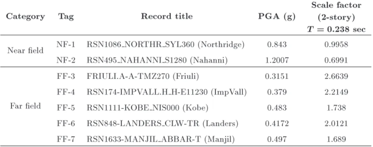
Table 5. Selected ground motions and scale factors for two-story braced frames.
Category Tag Record title PGA (g)
Scale factor (2-story) T = 0:238 sec Near eld NF-1 RSN1086 NORTHR SYL360 (Northridge) 0.843 0.9958
NF-2 RSN495 NAHANNI S1280 (Nahanni) 1.2007 0.6991
Far eld
FF-3 FRIULI.A-A-TMZ270 (Friuli) 0.3151 2.6639 FF-4 RSN174-IMPVALL.H H-E11230 (ImpVall) 0.379 2.2149
FF-5 RSN1111-KOBE NIS000 (Kobe) 0.483 1.738
FF-6 RSN848-LANDERS CLW-TR (Landers) 0.4172 2.0121 FF-7 RSN1633-MANJIL ABBAR-T (Manjil) 0.497 1.689
from the database available on IranHazrd Website [28] for the geographical location of the site. The design response spectrum parameters presented in Table 4 were calculated as prescribed in ASCE 7{10.
A suite of seven ground motions, including 2 near-eld and 5 far-eld records, for the site class and seismic hazard parameters of ASCE 7{10 were selected and scaled for two-story braced-frame buildings to design level earthquake hazard as listed in Table 5. Figure 12 shows response spectrum of scaled ground
motions. Average response spectrum of seven records before and after scaling is compared with the design response spectrum in Figure 13.
4. Results and discussion
Results of numerical simulation of chevron braced frames by means of ABAQUS software are presented in this section. At the rst stage, similar to the experimental study of Sen et al. [23{25], cyclic
dis-Figure 12. Response spectrum of the scaled ground motions.
Figure 13. Comparison of average response spectrum of scaled records with design spectrum of ASCE 7{10.
placement control loading of roof level was applied to the numerical model of the braced frames. Two main goals of further investigation into cyclic pushover loading were rstly, to extend results to multi-story, i.e. two- and four-story, braced frames with weak beams in all stories and secondly, to evaluate the eect of very weak beam section, which is commonly encountered in the existing chevron braced frames in Iran. In addition, analytical modeling enables nding dierent structural performance parameters. At the second stage, response history analysis of two-story model buildings subjected to scaled ground motions was performed to gain insight into seismic performance of chevron braced frames with weak beams posed to design level seismic hazard. Finally, seismic behaviors of two-story X and chevron four-story braced frames with weak beams were compared.
4.1. Cyclic pushover analysis of chevron braced frame
In cyclic pushover analysis, it is observed that, similar to the load history in Figure 4, maximum drift ratio of roof level increases step by step. Figures 14 and 15 show deformed shapes of two-story and four-story frames, respectively. Figures 16 and 17 respectively present responses of two-story and four-story frames in cyclic pushover analysis. In Figures 16 and 17,
Figure 14. Deformed shape of two-story chevron braced frame with scale factor of 5: (a) Strong, (b) weak, and (c) very weak.
Figure 15. Deformed shape of the four-story chevron braced frame with scale factor of 5: (a) Strong, (b) weak, and (c) very weak.
base shear is plotted versus story drift. Note that in cyclic pushover analysis, control displacement is only applied to roof level; thus, story shear of each level is equal to base shear. Out-of-plane buckling of braces in chevron braced frames with strong, weak, and very weak beams occurs in deformation at story drifts of 0.35% to 0.4%, as shown in Figures 14 and 15. When beam strength is sucient (Figures 14(a) and 15(a)), vertical deformation of beam is slight. De-creasing beam strength results in considerable increase in vertical deformation of beam (Figures 14(c) and 15(c)). High vertical deformation of beam, which is accompanied by buckling of compression brace, causes concentration of lateral displacement in few stories. Therefore, for weak and very weak beam cases, most of the lateral displacement is concentrated on one story, while for the strong beam case, lateral deformation is relatively uniform.
Adequate exural strength of beam leads to its limited vertical deformation and uniform height-wise lateral displacement distribution following brace buck-ling. Weak and very weak beams cause loss of lateral stiness and strength of the braced frame. Initially, all the frames have approximately equal lateral strengths, but the frame strength drops down suddenly as drift in-creases and consequently, compression braces buckle in weak beam and very weak beam cases. Further increase in lateral drift has small eect on the frame strength. In the case of two-story braced frame, the average
Figure 16. Comparison of the results for two-story chevron braced frame in cyclic pushover analysis: (a) Shear drift of frame, (b) shear drift of the rst story, (c) shear drift of the second story, (d) lateral stiness drift of frame, (e) lateral strength drift of frame, and (f) vertical deformation drift of the second-story beam.
strengths of frames with weak beams and very weak beams are reduced 31% and 52%, respectively, with respect to the frame with strong beam. For four-story braced frame, the average strengths of frames with weak and very weak beams decrease 19% and 42%, re-spectively, with respect to the frame with strong beam. The beam strength has direct eect on initial lateral stiness (elastic stiness) of the braced frames. The initial relative stiness of braced frames with weak and very weak beams is respectively 84% and 71% for two-story frame and 88% and 81% for four-story frame with respect to braced frame with strong beam. The lateral stiness of all braced frames gradually decreases as lateral drift increases, but lower beam strength causes higher rate of stiness reduction
(in average, 25% decrease for the weak beam and 50% decrease for the very weak case with respect to the strong beam). Thus, reduction in lateral stiness and lateral strength of the chevron braced frames is enhanced with decrease in exural strength. The combination of lower lateral strength and decrease in lateral stiness may cause soft or weak story for the frames with weak and very weak beams.
4.2. Nonlinear response history analysis of two-story chevron braced frames
Seven ground motions, as presented Table 2, were scaled to code-based design level records, which were used for response history analysis of two-story chevron braced frames. It is worth noting that the mass of
Figure 17. Comparison of the results for four-story chevron braced frame in cyclic pushover analysis: (a) Shear drift of frame, (b) shear drift of the rst story, (c) shear drift of the second story, (d) shear drift of the third story, (e) shear drift of the fourth story, (f) lateral stiness drift of frame, (g) lateral strength drift of frame, and (h) vertical deformation drift of the second-story beam.
tributary area of each frame (one fourth the plan area in Figure 11) was assigned to each story of the frame, and because the plan was symmetric, only one component of ground motion was applied to the plane of the frame in the numerical simulation.
Figure 18 shows the scaled deformed shape of two-story frames subjected to scaled FF-6 record (Landers) at maximum roof displacement time. In all cases, out-of-plane buckling of the braces occurred. For the strong beam (Figure 18(a)), vertical deformation of beam was
Figure 18. Deformed shape of the two-story chevron braced frame with scale factor of 4 subjected to FF-6 record at peak roof displacement: (a) Strong, (b) weak, and (c) very weak.
relatively small. As exural capacity of the beam decreased, vertical deformation considerably increased; thus, like in the cyclic pushover analysis, concentration of lateral displacement in one or two stories was expected. This exural deformation of beam caused buckling of compression brace and prevented yielding of tension brace, which was not the predened expected lateral behavior of braced frames. Formation of a soft rst story was generally observed.
Eects of beam strength on base shear in com-parison with drift of roof and the rst story subjected to FF-6 record are presented in Figures 19. When the beam is weak, strength degradation and stiness reduction lead to brace buckling.
History of mid-span vertical deformation of the rst-story beam under FF-6 earthquake is shown in Figure 20. Strong beam results in limited vertical mid-span deection, which enables yielding of tension brace. In contrast, low strength leads to yielding of the beam and consequently, large beam deection, which prevents yielding of tension brace after buckling of compression brace. In fact, axial force of tension brace is limited to beam shear load-carrying capacity, which is related to mid-span exural hinge formation mech-anism. For weak and very weak beams, considerable residual vertical deformation could be observed at the end of earthquake.
Figure 20. Mid-span vertical deformation history of the rst-story beam in two-story braced frame subjected to FF-6 earthquake.
Figure 21. Frame drift history of two-story braced frame subjected to FF-6 earthquake.
History of roof drift subjected to FF-6 earthquake is presented in Figure 21. After buckling of com-pression brace, frame drift is mostly concentrated in one direction. Generally, low-strength beam results in higher frame drift. Cumulative residual drift of the frame may occur, which is usually higher for braced frame with weak or very weak beam.
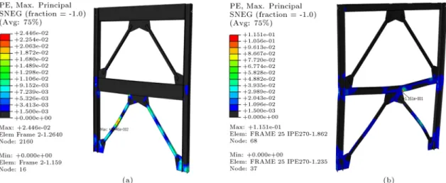
Plastic strain of members at peak displacement of the rst story is presented in Figure 22. No plastic strain could be observed in strong beams, which veries elastic behavior of the beam. As expected in the CBF system with adequate beam, the plastic strain in tension brace is related to yielding and plastic strain
Figure 19. Response of two-story braced frame under FF-6 record: (a) Base shear drift of frame and (b) base shear drift of the rst story.
Figure 22. Plastic strain at peak lateral displacement of the rst story in two-story braced frame subjected to FF-6 earthquake: (a) Strong beam and (b) very weak beam.
of compression brace is caused by post-buckling mid-span exural deformation of bracing. However, plastic strain mainly occurs in the beam of the braced frame with very weak beams, which represents plastic hinge formation. Large plastic strain of beam can possibly lead to beam failure, which needs ne modeling to be captured by means of FEM fracture modeling. No plastic strain could be observed in tension braces of frames with very weak beam, but compression braces experience buckling-related plastic strain. Some plastic strain occurs in the columns of the braced frame with very weak beam, which shows that larger shear is resisted by frame action of columns after brace buckling. Lower beam strength results in dierent load-carrying mechanism of the braced frame, in which part of lateral load is resisted through frame action instead of truss action.
Table 6 summarizes results of nonlinear response history analysis for all the scaled ground motions. The tabulated results include the maximum base shear, roof displacement, story to frame drift ratio, mid-span vertical displacement of beam, and unbalanced beam force. The unbalanced force is presented in terms of horizontal (axial) and vertical (shear) forces.
Regarding exural strength of the beam in the braced frame, the following points can be noted. Generally, the base shear does not depend on beam strength. The average lateral drifts of the frames with weak and very weak beams are 47% and 85% higher than those of the strong beam case. The buckling of the compression brace mostly occurs in the rst story. Thus, most of the lateral drift is concentrated on the rst story. In average, drift ratio of the rst story is 1.6%, 2.2%, and 3.1% for strong, weak, and very weak beams, respectively. This increase in the drift ratio of the rst story clearly demonstrates how inadequate beam can provoke formation of soft story. In addition, mid-span vertical deformations of the weak and very
weak beams in the rst story are 3.6 and 6.8 times that of the strong beam, respectively, which explains the higher drift ratio in the rst story.
Following AISC 341-10 provisions as presented in Table 3, the predicted unbalanced shear and axial forces in the strong beam were 648 and 1528 kN, respectively. This calculation was carried out by ignoring the depth of frame members and gusset plate dimensions. Thus, full-span length of 6 m and simple beam-column connection were considered. The average unbalanced shear and axial forces of the rst-story strong beam were 872 and 1865 kN, respectively. This dierence can mainly be attributed to strain hardening of steel in the tension brace. For instance, in the rst story of the braced frame with strong beam under FF4 record, maximum tensile force of elongated brace reached 1623 kN when compression force of buckled brace was 396 kN. Consequently, unbalanced shear force in the beam was, (1623-396) sin 46 = 902 kN which reasonably matched the reported value in Ta-ble 6. Furthermore, rigid behavior of the beam-column connection in the presence of corner gusset plates diered from the regular pinned connection behavior assumption.
The shear in the beam resulting from unbalanced force was proportional to exural strength, but the axial forces in all cases were relatively similar. It should be noted that compression brace buckling mostly oc-curs in the rst story; therefore, shear force in the rst-story beam is much more than that in the second-rst-story beam.
4.3. Cyclic pushover analysis of two-story X braced frame
To examine the inuence of bracing conguration on lateral behavior of a braced frame with very weak beam, nonlinear cyclic pushover analysis was employed and the results were compared with those for the
Table 6. Peak nonlinear dynamic response of two-story braced frame subjected to seven scaled records. Beam typ e Record tag Base shear (kN) Ro of lateral disp. (mm)
Drift ratio (%) Beam vertical
deection (mm) Beam unbalanceforce (kN)
Shear Axial 1st story 2nd story Frame 1st story 2nd story 1st story 2nd story 1st story 2nd story Strong
NF-1 2,347 64.4 1.665 0.364 0.977 16.4 2.1 967 98 1,954 1,785
NF-2 1,927 17.1 0.355 0.201 0.260 4.9 0.2 401 29 1,739 1,245
FF-3 2,336 84.4 2.230 0.339 1.280 16.7 3.7 993 94 1,895 1,612
FF-4 2,273 54.3 1.441 0.298 0.823 15.5 1.6 905 77 1,833 1,544
FF-5 2,434 83.3 2.226 0.344 1.263 22.0 5.6 993 95 1,944 1,650
FF-6 2,317 69.6 1.825 0.314 1.055 17.5 2.5 998 91 1,931 1,701
FF-7 2,266 51.4 1.361 0.324 0.779 13.6 1.9 851 87 1,759 1,788
Avg. 2,271.4 60.6 1.586 0.312 0.920 15.2 2.5 872.5 81.5 1,865.0 1,617.7
S.D. 149.8 21.4 0.595 0.050 0.324 4.8 1.6 199.1 22.2 82.4 173.0
W
eak
NF-1 2,133 93.9 2.313 0.646 1.424 58.2 12.2 703 266 1,854 1,646
NF-2 1,781 22.6 0.500 0.210 0.342 11.0 0.4 339 22 1,625 1,135
FF-3 2,103 121.2 2.471 1.565 1.838 59.3 39.4 698 452 1,783 1,582
FF-4 1,897 58.2 1.544 0.295 0.882 40.0 0.8 605 51 1,704 1,501
FF-5 2,046 97.8 2.613 0.362 1.483 62.3 3.9 635 54 1,721 1,584
FF-6 2,112 155.5 4.231 0.494 2.358 108.5 3.9 794 63 1,670 1,530
FF-7 1,945 75.1 1.955 0.385 1.139 48.0 1.2 673 55 1,716 1,550
Avg. 2,002.4 89.2 2.232 0.565 1.352 55.3 8.8 635.1 137.5 1,724.6 1,504.0
S.D. 122.2 39.8 1.052 0.428 0.604 27.1 13.0 133.2 148.9 69.3 156.7
V
ery
w
eak
NF-1 2,030 113.1 3.111 0.357 1.715 97.2 7.1 330 43 1,793 1,506
NF-2 1,866 22.2 0.531 0.200 0.337 15.9 0.2 162 6 1,673 996
FF-3 2,032 165.6 4.695 0.327 2.511 153.6 4.6 317 10 1,710 1,295
FF-4 1,754 66.9 1.794 0.248 1.015 67.7 2.1 261 11 1,601 1,173
FF-5 1,895 135.2 3.766 0.339 2.050 124.9 4.0 308 12 1,713 1,278
FF-6 2,004 190.3 5.452 0.358 2.886 175.4 4.9 341 14 1,819 1,309
FF-7 2,074 91.5 2.634 0.333 1.388 90.1 3.1 296 12 1,861 1,370
Avg. 1,950.7 112.1 3.140 0.309 1.700 103.5 3.7 287.9 15.5 1,738.6 1,275.4
S.D. 106.8 53.5 1.560 0.056 0.812 49.7 2.1 56.7 11.4 83.8 147.3
chevron CBF cases. Two-Story X Braced Frame (TSXBF) conguration, in which V- and inverted-V braces in alternate stories create an X-conguration over two stories, has become one of the most commonly used SCBFs in areas with high seismicity. Employing and studying TSXBF has drawn considerable atten-tion [29{31], because the brace-intersected beams in TSXBFs are much lighter than other CBF congu-rations such as chevron braced frames. According to AISC Seismic Provisions, the brace-intersected beams in TSXBFs can be designed considering the rst-mode lateral loading pattern, which reduces the vertical un-balanced loads acting on the brace-intersected girders of TSXBFs, especially if braces have similar cross sections. Following the seismic provisions, TSXBF with very weak beam (IPE270) can adequately carry lateral load eect.
The beam, column, and brace sections of TSXBF and chevron CBF with very weak beams are similar as listed in Table 2. Figure 23 presents deformed shapes of TSCBF, in which lateral drift mainly occurs in the second and third stories. At maximum frame drift of 1.4%, drifts of the rst, second, third, and fourth stories were 0.7%, 2.3%, 2.1%, and 0.4%, respectively.
Figure 24. Comparing results of four-story TSXBF and Chevron CBF in cyclic pushover analysis: (a) Shear drift of frame, (b) shear drift of the rst story, (c) shear drift of the second story, (d) shear drift of the third story, (e) shear drift of the fourth story, (f) lateral stiness drift of frame, (g) lateral strength drift of frame, and (h) vertical deformation drift of the third-story beam.
CBF are compared in Figure 24. The maximum vertical deformation of the beam in TSXBF is 30 mm and the maximum beam deections are respectively 26, 70, and 120 mm for chevron braces with strong, weak, and very weak beams. For TSXBF, the
av-erage strength of the frame decreases by 17% with respect to the chevron CBF with strong beam. The initial relative stiness of TSXBF in comparison with chevron braced frame with strong beam is 86%, but the average lateral stiness of TSXBF is 24% lower
than that of CBF with strong beam. Decreasing beam strength results in considerable increase in vertical deformation of beam (Figure 14(b) and (c)). The two-story X conguration prevents lateral strength drop when lateral drift increases, as can be observed in the chevron CBF with weak or very weak beam. It is apparent that two-story X conguration retrieves the adverse eect of beam weakness to some extent, but comparing lateral strength and stiness reveals that the chevron braced frame with appropriate beam has superior seismic behavior.
5. Conclusions
Results of numerical simulation of two- and four-story chevron CBFs with strong, weak, and very weak braced-intersected beams through nonlinear cyclic pushover analysis and nonlinear response history anal-ysis were presented. The numerical simulation per-formed by means of ABAQUS software was able to capture nonlinear steel material, buckling, and post-buckling behaviors of compression braces; presence and details of gusset plates; and large deformation eects. Adequacy of numerical simulation was veried by comparing the results of the model with those of an experimental study of two-story chevron braced frame with weak beam. Seismic responses were discussed in terms of lateral stiness and lateral strength of frame, vertical deformation and unbalanced force in beam, and inter-story drift ratios. Seismic behavior of two-story X braced frame in mitigating adverse eect of weak beam in chevron braced frame was also discussed. Major ndings of this study were as follows:
1. The beam in chevron braced frame underwent large unbalanced shear force proportional to beam exural strength. In the strong beam case, small vertical deformation occurred at beam mid-span, tension brace could yield, lateral force was mainly carried through truss action of braced frame, and relatively uniform height-wise lateral deformation was observed;
2. When exural strength of the beam was not su-cient, e.g., in weak and very weak beam cases, mid-span vertical deformation of the beam was high, tension brace remained almost elastic, braced frame supported lateral force by truss action and frame action, and the yielding beam concentrated lateral drift on a soft story;
3. Employing two-story X braced frame conguration could not completely retrieve the adverse eect of weak beam in chevron CBF. Chevron CBF with strong beam had higher lateral stiness and strength than `TSXBF' with very weak beam;
4. The necessity of providing the required strength for the beam of the chevron braced system was
clearly demonstrated. The chevron braced frame with strong beam had superior seismic behavior. References
1. ANSI, AISC \Seismic provisions for structural steel buildings (ANSI/AISC 341-10)", American Institute of Steel Construction, Chicago (IL), US (2010). 2. INBC, \INBC 10-12", Design and Construction of
Steel Buildings, Tehran, Iran: Iran National Building Code (2012).
3. Robert, N. and Tremblay, R. \Seismic design and behaviour of chevron steel braced frames", In Proc. 12th World Conf. on Earthquake Engrg., Auckland, NZ (2000).
4. Rai, D.C. and Goel, S.C. \Seismic evaluation and upgrading of chevron braced frames", Journal of Con-structional Steel Research, 59(8), pp. 971{994 (2003). 5. Uriz, P. and Mahin, S.A. \Seismic performance assess-ment of concentrically braced steel frames", In Pro-ceedings of the 13th World Conference on Earthquake Engineering, Vancouver, Canada (2004).
6. Kim, J. and Choi, H. \Response modication factors of chevron-braced frames", Engineering Structures, 27(2), pp. 285{300 (2005).
7. Marino, E.M. and Nakashima, M. \Seismic perfor-mance and new design procedure for chevron-braced frames", Earthquake Engineering & Structural Dynam-ics, 35(4), pp. 433{452 (2006).
8. Dicleli, M. and Mehta, A. \Eect of near-fault ground motion and damper characteristics on the seismic per-formance of chevron braced steel frames", Earthquake Engineering & Structural Dynamics, 36(7), pp. 927{ 948 (2007).
9. Dicleli, M. and Mehta, A. \Simulation of inelastic cyclic buckling behavior of steel box sections", Com-puters & Structures, 85(7), pp. 446{457 (2007). 10. Hines, E.M., Appel, M.E., and Cheever, P.J.
\Col-lapse performance of low-ductility chevron braced steel frames in moderate seismic regions", Engineering Journal, American Institute of Steel Construction, 46(3), pp. 149{180 (2009).
11. Giugliano, M.T., Longo, A., Montuori, R., and Piluso, V. \Seismic reliability of traditional and innovative concentrically braced frames", Earthquake Engineering & Structural Dynamics, 40(13), pp. 1455{1474 (2011). 12. Tong, G.S., Luo, G.F., and Zhang, L. \Lateral re-sistance of chevron-braced frames with weak beams", Engineering Mechanics, 28(8), pp. 89{98 (2011). 13. Zhang, L., Luo, G.F., and Tong, G.S. \Behaviour
of chevron bracing system of weak beam in resisting lateral force", Engineering Mechanics, 31(1), pp. 104{ 112 (2014).
16. Lai, J.W. and Mahin, S.A. \Strongback system: A way to reduce damage concentration in steel-braced frames", Journal of Structural Engineering, 141(9), p. 04014223 (2014).
17. D'Aniello, M., Costanzo, S., and Landolfo, R. \The in-uence of beam stiness on seismic response of chevron concentric bracings", Journal of Constructional Steel Research, 112, pp. 305{324 (2015).
18. Asghari, A. and Azimi, B. \Evaluation of sensitivity of CBFs for types of bracing and story numbers", Scientia Iranica, Transaction A, Civil Engineering, 24(1), p. 40 (2017).
19. Kazemzadeh Azad, S., Topkaya, C., and Astaneh-Asl, A. \Seismic behavior of concentrically braced frames designed to AISC341 and EC8 provisions", Journal of Constructional Steel Research, 133, pp. 383{404 (2017).
20. Fukuta, T., Nishiyama, I., Yamanouchi, H. and Kato, B. \Seismic performance of steel frames with inverted V braces", Journal of Structural Engineering, 115(8), pp. 2016{2028 (1989).
21. Bubela, R.K., Ventura, C.E., and Prion, H.G. \Cyclic testing of steel chevron braces with vertically slotted beam connection", IJASE, 2(1), p. 50 (2010). 22. Okazaki, T., Lignos, D.G., Hikino, T., and Kajiwara,
K. \Dynamic response of a chevron concentrically braced frame", Journal of Structural Engineering, 139(4), pp. 515{525 (2012).
23. Sen, A.D., Sloat, D., Pan, L., Roeder, C.W., Lehman, D.E., and Berman, J.W. \Evaluation of the seismic performance of two-story concentrically braced frame with weak beams", In Proceedings of 5th International Conference on Advances in Experimental Structural Engineering, Taipei, Taiwan (2013).
24. Sen, A.D., Pan, L., Sloat, D., Roeder, C.W., Lehman, D.E., Berman, J.W., Tsai, K.C., Li, C.H., and Wu, A.C. \Numerical and experimental assessment of chevron braced frames with weak beams", In Pro-ceedings 10th US National Conference of Earthquake Engineering, Anchorage, Alaska, US (2014).
25. Sen, A.D., Roeder, C.W., Berman, J.W., Lehman, D.E., Li, C.H., Wu, A.C., and Tsai, K.C. \Experi-mental investigation of chevron concentrically braced frames with yielding beams", Journal of Structural Engineering, 142(12), p. 04016123 (2016).
28. www.iranhazard.mporg.ir/
29. Shen, J., Wen, R., Akbas, B., Doran, B., and Uckan, E. \Seismic demand on brace-intersected beams in two-story X-braced frames", Engineering Structures, 76, pp. 295{312 (2014).
30. Wen, R., Seker, O., Akbas, B., and Shen, J. \Designs of special concentrically braced frame using AISC 341-05 and AISC 341-10", Practice Periodical on Structural Design and Construction, 21(1), p. 04015011 (2015). 31. Shen, J., Wen, R., and Akbas, B. \Mechanisms in
two-story X-braced frames", Journal of Constructional Steel Research, 106, pp. 258{277 (2015).
Biographies
Seyed Mehdi Dehghan is an Associate Professor in Civil and Environmental Engineering Department at Shiraz University of Technology. He received his BSc and MSc degrees from Shiraz University Shiraz, Iran. Also, he received his PhD degree in Structural Engi-neering from Tohoku University, Japan, in 2008. His research interests include seismic behavior of steel, RC, and masonry structures; passive control of structures; and seismic isolation.
Mohammad Amir Najafgholipour is an Associate Professor in Civil and Environmental Engineering De-partment at Shiraz University of Technology Shiraz, Iran. He received his BSc, MSc, and PhD degrees from Shiraz University in 2004, 2007, and 2012, respectively. He was on a sabbatical at Minho University, Portugal, in 2011. His main areas of research interest are seismic performance evaluation and retrotting of existing buildings, and experimental and numerical studies of masonry and RC structures. He now serves as a com-mittee member of the Iranian National Building Code for Design and Construction of Masonry Buildings. Hossein Hooshangi is currently a PhD candidate at Shiraz University of Technology, Shiraz, Iran. He received his MSc degree from the same university in 2015. He is interested in seismic behavior and numeri-cal simulation of dierent steel structural systems.