Sharif University of Technology
Scientia IranicaTransactions D: Computer Science & Engineering and Electrical Engineering http://scientiairanica.sharif.edu
Providing transient stability by excitation system
response improvement methods through long-term
contracts
A. Khandani and A. Akbari Foroud
Faculty of Electrical and Computer Engineering, Semnan University, Semnan, Iran. Received 6 April 2016; received in revised form 31 December 2016; accepted 30 May 2017
KEYWORDS Excitation systems; Transient stability; Single machine equivalent (SIME); Transient Stability Constrained
Optimal Power Flow (TSC-OPF).
Abstract. Maintaining network stability and encouraging generation companies to get involved in stability-maintaining objective are major concerns of an Independent System Operator (ISO) in a deregulated power system. Excitation system of synchronous generators is eective and well-known equipment, which has a signicant eect on network stability. Therefore, improving performance of this system can enhance network stability. However, utilizing the methods that improve the performance of excitation system imposes cost on generation companies. This paper proposes a motivation mechanism for enhancing transient stability that encourages generation companies to improve performance of excitation system. In this mechanism, besides excitation system response improving methods, a transient stability constrained optimal power ow is solved in order to ensure maintaining transient stability under dierent contingencies. A 4-bus test system, an IEEE 14-bus test system, and an IEEE 118-bus test system are used to illustrate the eectiveness of the proposed mechanism. Implementation results show that the proposed mechanism not only provides required transient stability margin with minimum operation cost, but also does not restrict generators production capability.
© 2019 Sharif University of Technology. All rights reserved.
1. Introduction
Transient stability is the ability of power systems to maintain synchronism in the event of large distur-bances. Such disturbances can increase generators' rotor angle deviation; therefore, if corrective actions fail, synchronization with the network will be lost [1]. Excitation system of synchronous generators is ef-fective for primary control action, which maintains transient stability of power systems. Excitation system supplies required eld current to keep generator in
*. Corresponding author. Fax: +98-23-33654089 E-mail addresses: [email protected] (A. Khandani); [email protected] (A. Akbari Foroud) doi: 10.24200/sci.2017.4511
synchronization with the network. A quick excitation system response can increase synchronization torque of a generator in order to maintain synchronism with the network. As a result, the response rate of excitation system has a signicant eect on network stability. Various parameters aect performance of the excitation system. These parameters include ceiling voltage, ceiling current, nominal response of the system, voltage excitation system response time, etc. Numerous meth-ods have been proposed to modify these parameters for improving performance of the excitation system that can be divided into three general categories:
1. Expansion capability of excitation system;
2. Improvement response of controller;
Exceeding of overexcitation limit, Generator Capabil-ity Curve (GCC) expansion, control response improve-ment, and High Side Voltage Control (HSVC) are some of these methods. These methods are called `improving methods' in this paper. Simple implementation and operation, non-restriction of generators production ca-pability, and good performance are some features of the improving methods. While installation and operation costs of the improving methods discourage Generation Companies (GenCos) from utilizing these methods. If GenCos do not utilize the improving methods, other preventive control actions may be used to enhance network stability.
Changes in generators operation points can be one of the preventive control actions for providing network stability. In this method, operation points of genera-tors are modied to make system stable in probably disturbances. Transient Stability Constrained Optimal Power Flow (TSC-OPF) is a preventive control action which is utilized to optimize operation point of gen-erators in order to provide transient stability of the system. This topic was discussed in several articles [2-6]. In [2-4], rotor angle equations were considered as a transient stability constraint in optimal power ow. As rotor angle equations were dierential equations, they were converted into an algebraic set of equations to solve TSC-OPF as a standard nonlinear optimization. Researchers in this eld focus on converting dierential equations and solving standard TSC-OPF. In [2], au-thors converted the dierential equations into numeri-cal equivalent algebraic ones and used a standard non-linear programming technique for solving TSC-OPF. In [3], authors proposed an enhanced discretization method to reduce the converted system dimension and improve computational eciency of the optimization algorithm. In [4], authors modelled transient stability as an objective function besides active power cost and, then, solved this multi-objective optimization by Non-dominated Sorting Genetic Algorithm II (NSGA-II). In [5,6], time domain simulation was performed to analyse transient stability of the system and simulation results were utilized in optimal power ow. In [5], simulation results determined critical and non-critical generators of the system. Critical generators were the generators that lose synchronism in the event of contingency. In that method, active powers of the critical generators were decreased to enhance the transient stability of the system. In [6], results of time domain simulation were converted into a single equation as a transient stability constraint in OPF. Active power of generators, machine angle, magnitude and angle of buses voltage, and other optimization variables were used to determine the initial operation point to increase transient stability of the system. In that paper, the initial operation point was changed to satisfy transient stability constraint. In addition, some
new methods based on modern heuristic methods were used to solve TSC-OPF [7]. In [7], authors proposed a method to estimate Critical Clearing Time (CCT) by the dual-kriging method. Results of this estimation were included in a single transient stability constraint of the TSC-OPF. Therefore, dierential algebraic equa-tions were excluded from TSC-OPF and standard opti-mization method was used to solve problem. Authors in [8] reviewed dierent TSC-OPF methods and im-plemented some of these methods. In addition, merits and demerits of the studied methods compared to each other were investigated in [8]. However, it should be considered that all the above-mentioned TSC-OPF methods cause an increase in the operation cost of the system, because active power outputs of generators are rescheduled in order to increase transient stability of the system. Moreover, restriction of active and reactive power generation due to the changing of the generators operation points is another disadvantage of those methods.
As described, utilizing of the improving meth-ods for excitation system response imposes costs on GenCos, thus discouraging them from utilizing these methods. On the other side, other preventive meth-ods for providing transient stability, such as TSC-OPF, cause an increase in system operation cost and restrict generators capacity. Therefore, this paper proposes a motivation mechanism to encourage GenCos to utilize the improving methods. Transient stability enhancement by utilizing the improving methods does not change optimal operation point of the system in which system operation cost is minimal. If the desired transient stability margin is not provided only by utilizing the improving methods, then a change in generators' operation points is used to provide the much needed stability margin. In this paper, TSC-OPF is used alongside the improving methods to minimize the cost of active power rescheduling and provide the desired transient stability of the system. Innovations and contributions of this paper are summarized as follows:
1. The proposed mechanism maximizes transient sta-bility and minimizes operation cost of the system by considering eects of the improving methods on network stability;
2. This mechanism provides required motivation for GenCos to utilize the improving methods;
3. In this mechanism, GenCos capacity for power generating is not restricted;
4. In this mechanism, operation point of the system for providing transient stability is the same operation point that minimizes network operation cost;
and TSC-OPF are considered for providing tran-sient stability.
The rest of the paper is organized as follows. The second section describes the improving methods for excitation system response. The third section in-troduces the methodology used in transient stability analysis. The `transient stability providing' mechanism is presented in Section 4. Section 5 investigates the case study, and Section 6 concludes this paper.
2. The improving methods for excitation system response
Performance of excitation system aects stability of the system. Results of previous researches show that a fast-response AVR and a high ceiling voltage exciter signicantly reduce rst rotor angle swing of generators in the event of contingency [9]. Excitation system response depends on the controller and limitation of the excitation system. Therefore, in this section, four methods that aect the excitation system response are described. Overexcitation limit exceeding and Generator Capability Curve (GCC) expansion enlarge the capability of the excitation system and cause an increase in the ceiling voltage of the exciter. Controller response improvement and High Side Voltage Control (HSVC) enhance control performance of excitation system and cause a decrease in response time of the control system.
2.1. Overexcitation limit exceeding
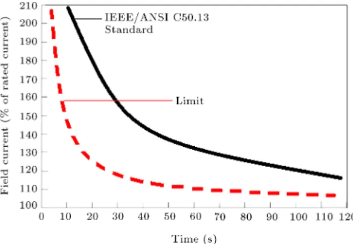
Active and reactive power generation limits of the synchronous generator are dened by its capability curve. Capability of generating reactive power is usually limited by the eld winding current. Overexci-tation limit is the upper limit of capability curve that restricts reactive power generation. This limit protects generator's rotor winding from overcurrent in a steady-state operation. IEEE/ANSI C50.13 is an operational standard for exceeding overexcitation limit [10]. Ac-cording to this standard, generators' rotor winding can support short-time overloading. Figure 1 shows this standard curve that depicts the relationship between the excitation current exceeding and acceptable delay for reducing this current. Some papers discussed the importance of OEL modelling and its eect on network stability in [11,12]. Moreover, authors in [13] studied the eect of the excitation ceiling voltage ratio on transient stability, and experimentally illustrated that the increase of excitation ceiling voltage improves transient stability of the system. Therefore, accurate modelling of OEL was studied in some papers, and dierent models were proposed for OEL modelling.
Overheating may occur in rotor winding due to the delay of the control equipment, time of heat reduction after eld current decreasing, and repetitive
Figure 1. Coordination of OEL and IEEE/ANSI C50.13 standard.
occurrence of overloading [14]. In typical OEL, a se-curity margin is considered to protect the synchronous generator from overheating. Figure 1 shows the margin between the actual implementation of OEL (the dotted curve) and IEEE/ANSI C50.13 standard (the solid curve). Reduction of this security margin can increase output power of the generators and enhance the system stability. The authors in [14] proposed an advanced OEL that allows the generator to supply power up to its maximum limits by reducing this security margin. In that method, limiting margin of overexcitation limiter was estimated based on the eld current and voltage measurement of the generator. The authors in [14] explained that the advanced OEL improved stability of the system and, also, protected generators eld winding from overheating.
2.2. Controller response
Numerous papers studied the excitation system re-sponse of synchronous generator and proposed various methods for improving this response. These papers demonstrated that the fast voltage control improved voltage stability and transient stability of the system. These methods include using the PID controller in AVR, using the genetic algorithm and fuzzy logic approach to tuning AVR, adjusting the coecients of the excitation system for achieving better response, etc. [15-17].
Authors in [16] analysed performance of a com-bined genetic algorithm, radial basis function neural network, and Sugeno fuzzy logic approach to tuning a PID controller for an AVR system; they showed that this method could enhance transient response of the AVR system. In addition, authors in [17] used a Linear Quadratic Gaussian (LQG) control method to design a wide area damping controller. Simulation results of [17] showed that the proposed LQG controller improved inter-area oscillation damping and enhanced small signal and transient stability of the system.
Figure 2. Construction of the HSVC method [19].
2.3. High side voltage control
The advanced High Side Voltage Control (HSVC) regulator controls high side voltage of the generator transformer without using a direct feedback. Structure and implementation of the HSVC have been obtained by upgrading auxiliary generator excitation control systems such as Line Drop Compensation (LDC) and the Power System Voltage Regulator (PSVR). HSVC improves voltage stability and enhances rotor angel stability of the system [18].
Authors in [19] studied the eect of HSVC on static voltage stability and damping of oscillation in power systems. Moreover, HSVC increases loadability of the system [19]. Figure 2 depicts construction of the advance HSVC.
2.4. Expansion of generator capability curve Excess heat from generators must be reduced to keep dierent components of the generator at predetermined temperatures. Utilization of hydrogen is a common method for cooling the generator in modern power plants. In hydrogen cooling generators, the hydrogen pressure is increased to expand the capability curve of the generator. Similarly, in the cooling air generator, the cooling air temperature is decreased to expand the capability curve of the generator. Figure 3 shows the expansion of the Generator Capability Curve (GCC) by reducing the cooling air temperature from 46C to
34C [20]. Authors in [20] proposed a method in order
to modify OEL, Under Excitation Limit (UEL), and other excitation system limits in response to changes in a coolant condition such as hydrogen pressure or cooling air temperature. Therefore, expansion of generators capability curve increases their production capacity.
3. Transient stability analysis
Several methods for transient stability analysis inves-tigate eects of the improving methods on transient stability. These methods can be divided into three
Figure 3. Expansion of the Generator Capability Curve (GCC).
general categories [21]: time domain simulation, direct method, and hybrid method. Time Domain Simulation (TDS) method simulates the dynamic behaviour of the system very close to its real operation and allows using the detailed model in the simulation [1]. However, this method is not able to determine the cause of instability, margin of stability, and design adequate control measures. In addition, the burden of the computation for solving dierential equations is the weakness of this method [1]. On the other side, a direct method limits the analysis of power system transient stability to during-fault period and, thus, reduces computation burden. The main problem of this method is system simplication that causes equipment modelling restriction. Therefore, in this paper, a hybrid method is used in order to combine advantages of the TDS method and direct method. The necessity of the accurate modelling of the system equipment, especially generator's excitation system and overexci-tation limit, leads one to use TDS. In addition, critical generators are required to be determined, causing system instability; therefore, transient stability margin of the system leads to the use of the direct method.
In this paper, a single-machine equivalent method (SIME) is used to connect TDS method with the direct method. In the SIME method, a multi-machine system is reduced to a two-machine model and, then, reduced to a One-Machine Innite Bus (OMIB) system [1]. The fact that a multi-machine system can be reduced to an OMIB is well known in power system. However, previous methods restricted modelling of the system. The main achievement of the SIME method is that any modelling level for a large power system can be considered. SIME correlates TDS method with Equal
Area Criterion (EAC) and provides a very important advantage, that is, identication of critical machines responsible for the system instability.
In the SIME method, a heuristic limit on rotor an-gle deviation, which is derived from TDS, rst identies critical generators; then, two groups of machines can be considered: critical and non-critical groups. Afterward, these two groups are converted into a two-machine system; then, this two-machine system is reduced to an OMIB through Eqs. (1)-(7). Now, transient stability of the system can be analysed by ECA for the OMIB. The following equations are used to convert a detailed model of power system into an OMIB. A more detailed description of SIME can be found in [1].
(t) M1
C
X
K2C
MKK(t) M1 NC
X
j2NC
Mjj(t);
(1)
Pm(t)=M
0 @ 1
MC
X
k2C
Pmk(t) M1 NC
X
j2NC
Pmj(t)
1 A ;
(2)
Pe(t)=M
0 @ 1
MC
X
k2C
Pek(t) M1 NC
X
j2NC
Pej(t)
1 A ;
(3) Pa(t) = Pm(t) Pe(t); (4)
MC=
X
K2C
MK; (5)
MNC =
X
j2NC
Mj; (6)
M = MMCMNC
C+ MNC: (7)
In the above equations, j(t) is the rotor angle,
Pmj(t) is the mechanical power, Pej(t) is the electrical
power, and Mj is the inertia coecient for generator
j. In addition, (t) is the rotor angle, Pm(t) is the
mechanical power, Pe(t) is the electrical power, Pa(t)
is the accelerating power, and M is the inertia coe-cient of the corresponding OMIB. In these equations, subscript C represents a critical group, and subscript NC represents a non-critical group.
4. Motivation mechanism for providing transient stability
Providing and installing new control equipment has long-term eects on the system, enhancing transient stability of the system. However, imposed cost on GenCos, due to installing new control equipment, dis-courages these companies from utilizing the improving methods. Therefore, this paper proposes a long-term
contract between ISO and GenCos for providing tran-sient stability of the system. In this contract, ISO rst determines required stability margin (required Critical Clearing Time-CCT). Afterward, GenCos undertake to provide this stability margin and, reciprocally, ISO pays transient stability providing the cost to them. The cost of providing transient stability can be determined based on the value of transient stability for ISO, which can be considered as the amount of cost that ISO must pay for providing this stability margin by other methods (such as changes in generators active power). ISO can pay part of this saved cost to GenCos in order to encourage them to utilize the improving methods. Utilization of these methods denitely has a lower cost in comparison to the other methods for providing transient stability. Advanced OEL and HSVC are implemented as software functions in a digital AVR similar to other functions of digital AVR such as Power System Stabilizer (PSS), Line Drop Compensator (LDC), etc. [14]. Controller response improvement can be performed by conguring AVR for a better response. Expansion of the generator capability curve can be carried out by the coordination between limitations and protection functions of excitation system for better cooling operation; therefore, it can be implemented using excitation system functions [20]. Therefore, part of the saved cost due to the use of improving methods can compensate GenCos cost for utilizing these methods.
4.1. Procedure of the proposed mechanism Figure 4 shows the owchart of the proposed mech-anism for providing desired transient stability of the system. A step-by-step implementation procedure of this mechanism is described in the following:
1. In the proposed mechanism, ISO rst contracts with GenCos for providing desired stability margin (contract between ISO and GenCos). The value of transient stability for ISO determines the amount of paid cost to GenCos by ISO. This value depends on several factors such as the importance of transient stability for the system and the cost of transient stability enhancement;
2. After contract, GenCos implement the improve-ment methods that are improve-mentioned in agreeimprove-ment between GenCo and ISO;
3. The improved network is the studied network in the initial operation point in which the improving methods are implemented in excitation systems of generators;
4. A conventional OPF is run to determine the optimal power ow of the studied network based on GenCos' bids. In this step, a transient stability constraint is not considered;
Figure 4. Flowchart of the proposed mechanism.
5. Then contingency screening is carried out in the improved network to separate stable from unstable contingencies. Contingency screening is performed using SIME described in [22]. In this method, TDS is carried out for the system and, then, its results are utilized by SIME in order to evaluate the stability condition of contingencies. As utilizing the improving methods enhances transient stability of the system, it is expected that the number of critical contingencies reduces or the number reaches zero. In the case of unstable contingency, critical and non-critical generators, stability margin, and operation point of the system are saved and sent to step 7;
6. If all of the contingencies are stable, the procedure is nished; else, Transient Stability Constrained Optimal Power Flow (TSC-OPF) is performed for providing stability in unstable contingencies by rescheduling the critical generators;
7. Transient stability of the system can be increased by reducing the total active power of critical generators in the network. Eq. (8) is used to show the amount of active power which is generated by the critical generators. Pcgi is the amount of active power of
each critical generator in the network. P0 is the
total active power of critical generators in previous scheduling, and P is the amount of changes in active power of critical generators for enhancing
transient stability. The critical and non-critical generators are determined by the SIME method. Moreover, P is determined based on stability margin by the SIME method [1].
X
i2CG
Pcgi P0 P: (8)
The amount of P is shared between critical generators based on their angular deviation at instability time. In multi unstable contingencies, this P is shared between critical generators, which are common in unstable contingencies. Detailed descriptions of critical generators rescheduling can be found in [5].
8. TSC-OPF, which is described in the following sec-tion (Secsec-tion 4.2), is run for determining operasec-tion point of non-critical generators. It should be noted that the operation point of the critical generators was determined in step 7. After determining the operation point of all generators, the procedure goes back to step 5 to check the stability of the system in the new operating condition.
4.2. The TSC-OPF formulation
TSC-OPF is used to optimize operation point of the generators in order to provide transient stability of the system. Objective functions and constraints are described in the following. The amount of active power of non-critical generators represents decision variables. In addition, cost of active power rescheduling and new scheduling of generators are outputs of this optimization.
4.2.1. Objective function
The purpose of this paper is to maintain system stability with minimum operation cost by utilizing the improving methods. Therefore, the objective function of TSC-OPF is to minimize the total cost of active power rescheduling.
minX
i2G
C(Pi): (9)
4.2.2. Constraints
Equal constraints are production and consumption equality of active and reactive powers at each bus in the network.
Pgi Pli
X
j2
Pij(Vi; Vj; i; j) = 0; (10)
Qgi Qli
X
j2
Qij(Vi; Vj; i; j) = 0; (11)
where Pgi and Qgi are active and reactive powers
powers consumed at bus i; Pij and Qij are active and
reactive power ows between bus i and bus j. Vi and
i are voltage magnitude and voltage angle at bus i, respectively.
Non-equal constraints in the optimization are: Branch current limits:
Iij(Vi; Vj; i; j) Iijmax: (12)
Bus voltage limits: Vmin
i Vi Vimax: (13)
Restriction of active and reactive powers in genera-tors:
Pmin
gi Pgi Pgimax; (14)
Qmin
gi Qgi Qmaxgi : (15)
In this paper, TSC-OPF is only used to ensure provid-ing desired transient stability of the system, while the desired transient stability is not provided by the im-proving methods (i.e., the remaining transient stability margin will be supplied through changing generators' operation point). In this paper, the method presented in [5] is developed in order to comprise the improving methods in transient stability of the system. In this TSC-OPF, active power of critical generators is shifted to non-critical generators for providing transient sta-bility under unstable contingencies. As described, detailed modelling of system equipment induces us to use the method of [5]. Instead of this method, the method of [6] can be used for TSC-OPF that causes an increase in complexity of the problem.
5. Case study
In this section, the proposed mechanism for providing transient stability is analysed. This section has two separate parts. Inuence of the improving methods on transient stability is illustrated in the rst part, while results of the proposed mechanism implementation for providing transient stability are presented in the second part.
5.1. Eects of the improving methods on transient stability
A 4-bus network, which is shown in Figure 5, is simulated in MATLAB. The dynamic model of a synchronous generator and supplementary equipment (including hydraulic turbine, governor, and a ST1 excitation system) are simulated in MATLAB [23]. The OEL model of [11] is used in simulation. HSVC is implemented based on the model of [19].
To study the eect of the improving methods, the dynamic behaviour of the system will be discussed in
Figure 5. A simple 4-bus test network.
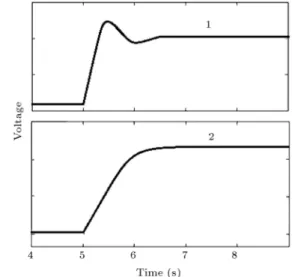
Figure 6. Controller response to a disturbance. 1: Fast response (300/0.001s+1); 2: slow response (50/0.001s+1).
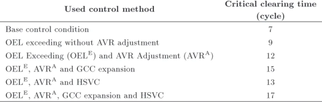
the presence of a three-phase short circuit in the line between buses 1 and 2. Table 1 shows the eect of the improving methods on transient stability of the system. Exceeding the rated current in the excitation system (by using standard ANSI C50.13) improves the transient stability of the system more than 5 cycles. In this situation, network will be stable in the presence of a 12-cycle 3-phase short circuit. To show the impact of AVR controller on transient stability, the coecients of the controller are congured as shown in Figure 6. In this gure, the rst controller has a fast response, and the second one has a slow response. Concomitant use of standard ANSI C50.13 and fast response controller make system stable over the 12-cycle short-circuit current.
As mentioned, expansion of generator capability curve is another method that aects system transient stability. In this paper, it is assumed that better cooling system of generators increases the output power of generators to 120% of nominal power. The network will be stable over the 15-cycle short-circuit current by considering this assumption and allowing OEL exceeding.
Table 1. Simulation results for enhancing transient stability of 4-bus network. Used control method Critical clearing time
(cycle)
Base control condition 7
OEL exceeding without AVR adjustment 9
OEL Exceeding (OELE) and AVR Adjustment (AVRA) 12
OELE, AVRA and GCC expansion 15
OELE, AVRA and HSVC 13
OELE, AVRA, GCC expansion and HSVC 17
Figure 7. IEEE 14-bus network.
Based on Table 1, the use of HSVC improves transient stability of the system. Using HSVC along with two other methods makes the system stable over the 17-cycle short-circuit current. This represents a 10-cycle improvement in transient stability of the system. 5.2. Implementation of the proposed
mechanism on IEEE 14-bus network IEEE 14-bus network, shown in Figure 7, is simulated in MATLAB in order to demonstrate the eectiveness of the proposed mechanism in providing transient stability. The dynamic model of the synchronous generators and supplementary equipment (including hydraulic turbine, governor, and a ST1 excitation system) are simulated in MATLAB. The OEL model of [11] is used in simulation. In addition, HSVC is implemented based on the model of [19]. The system transient stability is studied in two cases:
1. Three-phase fault occurs in transmission lines in order to determine the fault critical clearing time. The worst position of the short circuit is the nearest point to generators;
2. The second survey is the occurrence of single con-tingency in the network. This event occurs as a
tripped line outage after a short circuit (5 cycles after fault occurrence).
Studying three-phase short circuits near the gen-erators of the network determines that the most likely instability corresponds to the occurrence of short cir-cuits in line 1 between bus 1 and bus 2. In this situation, the system in base control condition can only sustain short circuits with 4 cycle's duration.
5.2.1. Fault critical clearing time
In order to compare the proposed mechanism, provid-ing transient stability, with the conventional method, two conditions are considered. In the rst condition, it is assumed that GenCos abstain from using the improving methods. Therefore, ISO uses conventional methods for providing transient stability. In this condition, active power of generators is rescheduled to increase stability margin of the system. This condition is called base control condition. The second one, in which the improving methods are used in all generators of this network, is called an improved network. Utilizing the improving methods provides whole or a part of desired transient stability margin. If the improving methods cannot satisfy the desired stability level entirely, a change in active power of generators is used, too.
Table 2 shows the results of transient stability provided for IEEE 14-bus network by the conventional method and the proposed mechanism. This table presents the amount of active power rescheduling for each of the generators, total rescheduling cost, and critical clearing time. In the base control condition, transient stability is improved by a change in gen-erators operation point. However, in the improved network, transient stability is provided by the proposed mechanism of this paper. Changes in generators operation point can improve transient stability of the system in only 5 cycles. Therefore, this method leads critical clearing time to 9 cycles for the base control condition. However, the proposed mechanism can improve the network transient stability over 9 cycles. Thus, utilizing the improving methods makes system stable for the 13-cycle short circuit. Comparing the results indicates that the improving methods not only
Table 2. Providing transient stability for IEEE 14-bus network.
Base control condition Improved network
Active power rescheduling for G1 (MW) -60.7 0
Active power rescheduling for G2 (MW) 58.7 0
Total rescheduling cost ($/h) 456.52 0
Critical clearing time (Cycle) 9 13
Table 3. Providing transient stability for critical contingencies by utilization of the improving methods. Contingency OEL
exceeding
AVR
adjustment HSVC
GCC expansion
Total power rescheduling
C1 X X X X 0
C2 X X | | 0
C3 X X | | 0
save 456 dollar per hour, but also improve network transient stability more than the conventional method. Dierent methods can be used to enhance tran-sient stability of the system. These methods include excitation system response improving methods [10-20], active power rescheduling [2-8], and FACTS devices installation [24-26]. Performances of the improving methods and active power rescheduling are compared in this paper. Another conventional method for transient stability enhancement is the installation of a Thyristor Control Series Capacitor (TCSC). Transient stability improvement by this method is dependent on the installing location of TCSC. For a better compari-son between the improving methods and conventional methods, a TCSC is installed in line 2 between bus 1 and bus 5. Installing this TCSC leads to the enhance-ment of transient stability of the system about 4 cycles. Therefore, the studied network is stable in the presence of 8-cycle short circuit in line 1 between bus 1 and bus 2. As expected, the use of this device has installation cost. This method imposes about 0.3 million dollar cost on ISO per year. This cost is calculated based on Eqs. (16)-(18) [27]:
CT CSC =0:0015ST CSC2 0:713ST CSC
+ 153:75 ($/KVAR); (16) ICT CSC = CT CSC ST CSC 1000 ($); (17)
AICT CSC = ICT CSC ir(1 + ir) LT
(1 + ir)LT 1 ($/year): (18)
In Eq. (17), CT CSC is cost of TCSC, and ST CSC is
operating range of TCSC. Investment cost is converted into annual cost by Eq. (18). In Eq. (18), lifetime (LT) of this equipment and interest rate (ir) are considered to be 15 years and 0.05, respectively.
Installation of the TCSC has lower cost in com-parison to rescheduling of active power. If rescheduling
of active power imposes 456 $/h on ISO just for 8 hours in a day (peak time), then this method may impose about 1.3 million dollar cost on ISO per year, while TCSC installation has 0.3 million dollar cost per year. However, each one of these two methods has considerable cost, as comparison to the improving methods of excitation system. Therefore, a part of saved cost due to the use of the improving methods (instead of active power rescheduling or TCSC instal-lation) can compensate for the cost imposed on GenCos for installing and using the improving methods. 5.2.2. Single contingency analysis
In order to investigate the transient stability of the network in case of single contingency, the method described in [22] is used to screen the contingencies. Therefore, only the events, which lead networks to instability, are examined. In this network, three single contingencies will lead to network instability. These contingencies include tripped line outage after a 3-phase short circuit with 5-cycle length in lines between bus 1 and bus 2 (C1), between bus 1 and bus 5 (C2), and between buses 2 and bus 5 (C3).
Transient stability for these events can be pro-vided by utilizing the improving methods. In occur-rence of C1, all of the improving methods (described in Section 2) are required to provide transient stability of the network. While transient stability for two other events can be provided by using AVR adjustment and OEL exceeding. Table 3 shows the related simulation results. As this table illustrates, utilizing the improving methods can provide system transient stability, and there is no need for the rescheduling of the generators. In order to compare the eectiveness of the proposed mechanism with that of the conventional method, a change in generators output is used to enhance transient stability of the network for these critical contingencies. Table 4 shows results of TSC-OPF implementation on the base control condition network, where active power rescheduling is used to
Table 4. Providing transient stability for critical contingencies by active power rescheduling. Contingency P 1 (MW) P 2 (MW) Total reschedulingcost ($/h) conditionStability
C1 -60.7 58.7 456.52 Unstable
C2 -30.7 29.23 259.56 Stable
C3 -10.7 10.14 31.26 Stable
Table 5. Results of transient stability analyses on IEEE 118-bus network for CCT determination. Contingency operatingInitial
condition
Transient stability providing method Active power
rescheduling
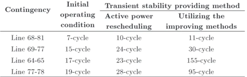
Utilizing the improving methods Line 68-81 7-cycle 10-cycle 11-cycle Line 69-77 15-cycle 24-cycle 30-cycle Line 64-65 17-cycle 23-cycle 155-cycle Line 77-78 19-cycle 28-cycle 95-cycle
enhance transient stability of the system instead of the improving methods. This table represents active power rescheduling for each of two generators, total reschedul-ing cost, and network stability status after TSC-OPF implementation. As the results illustrate, utilizing the conventional method (active power rescheduling) increases operation cost. In addition to this, active power rescheduling cannot maintain transient stability of the network in the event of C1.
5.3. Implementation of the proposed
mechanism in the IEEE 118-bus network In order to investigate the proposed mechanism in detail, IEEE 118-bus network is simulated in DigSi-lent. Simulation results show that this network in the initial operating condition can withstand a 7-cycle 3-phase short circuit on transmission line 68-81. In the initial operating condition, transient stability pro-viding method described in this paper is not utilized, and generators' operating conditions are derived from the conventional OPF. In order to enhance transient stability of this system, active power rescheduling is used by TSC-OPF implementation. As seen in Table 5, this method enhances transient stability of this system to 10 cycles for the 3-phase short circuit fault on transmission line 68-81. Moreover, the mentioned improving methods for the excitation system responses are used in this paper to increase transient stability of the system. Utilizing the improving method to achieve transient stability of the system enhances 11 cycles for 3-phase short circuit fault on transmission line 68-81.
In this network, in order to enhance transient stability by active power rescheduling, operation cost of the system will increase by $301.53 per hour. If this method is needed just for peak time transient stability providing, active power rescheduling increases by 880 thousand dollars per year. By comparing
implementation results of transient stability of provid-ing methods, it is clear that utilizprovid-ing the improvprovid-ing methods increases transient stability of the system much more than the active power rescheduling.
6. Conclusion
Dierent control methods were proposed to improve the excitation system response. As a result of this pa-per, utilizing the improving methods not only improves transient stability of the system, but also decreases network operation cost, whereas conventional methods, such as rescheduling of active power of generators, may be unable to provide transient stability of the system under some contingencies. However, utilizing the improving methods imposes costs on GenCos, discour-aging them from utilizing these methods. Thus, this paper proposed a motivation mechanism to encourage GenCos to utilize the improving methods through a long-term contract between ISO and GenCos. The proposed mechanism provides the required transient stability margin with minimum cost in comparison to the other methods. In this contract, GenCos are paid for utilizing the improving methods in order to provide required transient stability margin for the system. Utilizing the improving methods causes a decrease in the need for active power rescheduling for transient stability providing, thus reducing generators' restrictions for active power generation. Therefore, the proposed mechanism will benet GenCos and reduce network operating costs for providing the required transient stability margin.
References
1. Pavella, M., Ernst, D., and Ruiz-Vega, D., Transient Stability of Power Systems a Unied Approach to
Assessment and Control, Kluwer Academic Publishers (2000).
2. Gan, D., Thomas, R.J., and Zimmerman, R.D. \Stability-constrained optimal power ow", IEEE Trans. Power Syst., 15(2), pp. 535-540 (2000).
3. Jiang, Q. and Huang, Z. \An enhanced numerical dis-cretization method for transient stability constrained optimal power ow", IEEE Trans. Power Syst., 25(4), pp. 1790-1797 (2010).
4. Ye, C.J., and Xiang, H.M. \Multi-objective optimal power ow considering transient stability based on parallel NSGA-II", IEEE Trans. Power Syst., 30(2), pp. 857-866 (2015).
5. Ruiz-Vega, D. and Pavella, M. \A comprehensive approach to transient stability control: Part I-near optimal preventive control", IEEE Trans. Power Syst., 18(4), pp. 1446-1453 (2003).
6. Tu, X., Dessaint, L.A., and Nguyen-Duc, H. \Transient stability constrained optimal power ow using inde-pendent dynamic simulation", IET Gener. Transm. Distrib., 7(3), pp. 244-253 (2013).
7. Zerigui, A., Dessaint, L.A., Hannat, R., Ah King, R., and Kamwa, I. \Statistical approach for transient stability constrained optimal power ow" IET Gener. Transm. Distrib., 9(14), pp. 1856-1864 (2015).
8. Xu, Y., Dong, Z.Y., Xu, Z., Zhang, R., and Wong, K.P. \Power system transient stability-constrained optimal power ow: A comprehensive review", IEEE Power and Energy Society General Meeting, San Diego, CA, USA (2012).
9. Sun, Y.Z., Li, X., and Zhao, M. \New Lyapunov function for transient stability analysis and control of power systems with excitation control", Electric Power Systems Research, Elsevier, 57(2), pp. 123-131 (2001).
10. IEEE Std. C50.13, IEEE Standard for Cylindrical-Rotor 50 Hz and 60 Hz Synchronous Generators Rated 10 MVA and Above (2006).
11. Pajuelo, E., Gokaraju, R., and Sachdev, M.S. \Coor-dination of over excitation limiter, eld over current protection and generator control", IEEE Power and Energy Society General Meeting, Minneapolis, pp. 1-7 (2010).
12. Anagnostou, G. and Pal, B. \Impact of over excitation limiters on the power system stability margin under stressed conditions", IEEE Trans. on Power Systems, 31(3), pp. 2327-2337 (2016).
13. Yang, K., Zeng, Y., Zeng, J., Gao, Q., Wei, W., and Zhao, J. \Experimental studies on transient stability of power ratio of excitation interactions system ceiling voltage systems", IEEE Tencon, Bali, pp. 913-917 (2011).
14. Shimomura, M., Xia, Y., Wakabayashi, M., and Paserba, J. \A new advanced over excitation limiter for enhancing the voltage stability of power systems", IEEE Power Engineering Society Winter Meeting, Columbus, pp. 221-227 (2001).
15. Mohanty, P., Sahu, B., and Panda, S. \Tuning and as-sessment of proportional-integral-derivative controller for an automatic voltage regulator system employing local unimodal sampling algorithm", Electric Power Components and Systems, Taylor & Francis, 42(9), pp. 959-969 (2014).
16. AlGizi, A.J.H., Mustafa, M.W., Al-geelani, N.A., and Alsaedi, M.A. \Sugeno fuzzy PID tuning, by genetic-neutral for AVR in electrical power generation", Ap-plied Soft Computing, Elsevier, 28, pp. 226-236 (2015).
17. Bhadu, M., Senroy, N., Narayan Kar, I., and Nair Sudha, G. \Robust linear quadratic Gaussian-based discrete mode wide area power system damping con-troller", IET Gener. Transm. Distrib., 10(6), pp. 1470-1478 (2016).
18. An, J., Huang, G., Mu, G., Zheng, T., and Zhou, Y. \Optimal HSVC droop planning for the voltage prole improvements in bulk power systems", IEEE Power & Energy Society General Meeting, Denver, CO, USA (2015).
19. Akbari Foroud, A., Sei, H., and Khaki Sedigh, A. \Advanced HSVC tuning in multi-machine power systems for loadability improvement", Electric Power Components and Systems, Taylor & Francis, 34, pp. 689-706 (2006).
20. Lawson, R.A., Pearson, W.R., and Curran, J.E., Method and Apparatus for Modifying Limit and Protec-tion Software in a Synchronous Generator Exciter to Match the Capability of the Turbine Generator, Patent application publication, US6294898 (2001).
21. Kyriakidis, Th., Lanz, G., Cherkaoui, R., and Kayal, M. \A transient stability assessment method using post-fault trajectories", IEEE PowerTech, Grenoble, pp. 1-4 (2013).
22. Erns, D., Ruiz-Vega, D., Pavella, M., Hirsch, P., and Sobajic, D. \A unied approach to transient stability contingency ltering, ranking and assessment", IEEE Trans. Power Syst., 16(3), pp. 435-443 (2001).
23. http://www.mathworks.com/examples/simpower/50-synchronous-machine, accessed 3 June 2015.
24. Bakhshi, M., Holakooie, M.H., and Rabiee, A. \Fuzzy based damping controller for TCSC using local mea-surements to enhance transient stability of power sys-tems", Electrical Power and Energy Systems, Elsevier, 85, pp. 12-21 (2017).
25. Esmaeili Dahej, A., Esmaeili, S., and Goroohi, A. \Multi-objective optimal location of SSSC and STAT-COM achieved by fuzzy optimization strategy and harmony search algorithm", Scientia Iranica, D, 20(6), pp. 2024-2035 (2013).
26. Ghanizadeh, R., Ebadian, M., Golkar, M. A., and Ja-handideh Shendi, A. \Investigating performance of the new FC-MCR compensator for enhancing power sys-tem stability using multi-objective Imperialist Com-petitive Algorithm (ICA)", Scientia Iranica, D, 21(6), pp. 2200-2212 (2014).
27. Wibowo, R.S., Yorino, N., Eghbal, M., Zoka, Y., and Sasaki, Y. \FACTS devices allocation with control coordination considering congestion relief and voltage stability", IEEE Trans. on Power Systems, 26(4), pp. 2302{2310 (2011).
Biographies
Ali Khandani received the BS degree in 2009 from Iran University of Science and Technology and the MSc degree in 2012 from Bu-Ali Sina University. He is currently a PhD student in Semnan University,
Semnan, Iran. His research interests are in the power market, power system optimization, power quality, and power system operation and control.
Asghar Akbari Foroud received the BS degree from Tehran University and the MSc and PhD degrees from Tarbiat Modares University, Tehran, Iran. He became an Assistant Professor in 2006 and an Associate Professor in 2012 at Semnan University. His elds of interest are power system dynamics, operation and control, power market, power system planning, power quality, and power system distribution.
![Figure 2. Construction of the HSVC method [19].](https://thumb-us.123doks.com/thumbv2/123dok_us/8369897.2222940/4.892.477.826.148.485/figure-construction-of-the-hsvc-method.webp)