Model DSP7000
High Speed Programmable
Dynamometer Controller
While every precaution has been exercised in the compilation of this document to ensure the accuracy of its contents, Magtrol, Inc. assumes no responsibility for errors or omissions. Additionally, no liability is assumed for any damages that may result from the use of the information contained within this publication.
Copyright
Copyright ©2011-2016 Magtrol, Inc. All rights reserved.
Copying or reproduction of all or any part of the contents of this manual without the express permission of Magtrol is strictly prohibited.
trademarks
LabVIEW™ is a trademark of National Instruments Corporation. Microsoft® is a registered trademark of Microsoft Corporation.
National Instruments™ is a trademark of National Instruments Corporation.
Please record all model numbers and serial numbers of your Magtrol equipment, along with the general purchase information. The model number and serial number can be found on either a silver identification plate or white label affixed to each unit. Refer to these numbers whenever you communicate with a Magtrol representative about this equipment.
Model Number: _____________________________ Serial Number: _____________________________ Purchase Date: _____________________________ Purchased From: _____________________________
1. Make sure that all Magtrol dynamometers and electronic products are earth-grounded, to ensure personal safety and proper operation.
2. Check line voltage before operating the DSP7000.
3. Make sure that dynamometers and motors under test are equipped with appropriate safety guards.
The contents of this manual are subject to change without prior notice. Should revisions be necessary, updates to all Magtrol User’s Manuals can be found at Magtrol’s web site at www.magtrol.com/support/manuals.htm.
Please compare the date of this manual with the revision date on the web site, then refer to the manual’s Table of Revisions for any changes/updates that have been made since this edition.
revision date
2nd Edition revision K– April 2016
table of revisions
date edition Change section(s)
04/05/16 2 nd Edition rev. K Torque Commands updated. 7.4.6 08/10/15 2 nd Edition rev. J USB driver setup for Windows operating system updated. 7.1.1 07/07/15 2 nd Edition rev. H Installation instructions and commands updated
throughout chapter. Chapter 7 07/07/15 2 nd Edition rev. H Setting tare function instructions updated. 6.7.1 07/07/15 2 nd Edition rev. H Alarm instuctions and commands updated throughout
chapter. Chapter 5
06-09-15 2 nd Edition rev. G Figure 2-12 RS-232 Interface drawing updated. 2.4.4 06/19/14 2 nd Edition rev. F A/D Sample Rate changed from 7812.5 KHz to 7812.5 Hz. 10.3 03/27/14 2 nd Edition rev. E Miscellaneous Commands updated. 7.4.7 10/28/13 2 nd Edition rev. D Speed commands table updated.
Figure 4-1 updated for new firmware. Section updated for new firmware.
7.4.5 4.3.1 6.6 07/11/13 2 nd Edition rev. C Note added to Calibration Frequency procedure. 9.3.4 07/03/13 2 nd Edition rev. B Step number 5 updated in Calibration Procedure of Digital
to Analog Converters. 9.3.3 07/03/13 2 nd Edition rev. B Step number 4 updated in Calibration Prodedure of
Analog to Digital Converters. 9.3.2 05/23/13 2 nd Edition rev. A Calibration procedure of Analog to Digital Converters
updated. 9.3.2
05/23/13 2 nd Edition rev. A Digital input and output added to specifications. 8.1 03/09/13 2 nd Edition Torque invert signal added. B.3.4
03/09/13 2 nd Edition Prcedure for setting the scale factor updated. 10.2.1.1, 10.2.1.2, 10.2.1.3
03/09/13 2 nd Edition Calibration Procedure updated. 9.3, 9.3.3 03/09/13 2 nd Edition New drawing added. 8.2.3, 8.2.4 03/09/13 2 nd Edition Pin 25 updated to Alarm Relay 2 Common. 8.1.2 03/09/13 2 nd Edition QDS1,xx.xx, QDS2,xx.xx; QIS1,xx.xx, QIS2,xx.xx;
QPS1,xx.xx, QPS2,xx.xx commands updated. 7.4.6 03/09/13 2 nd Edition NDSI1,#, NDSI2,#; NISI1,#, NISI2,#; NPSI1,#, NPSI2,# 7.4.5
TAC1,#, TAC2,# command updated.
03/09/13 2 nd Edition Drawing updated 3.2.4.1, 3.2.5.1, 3.2.7.1, 3.2.8.1, 3.2.9.1, 3.2.10.1 03/09/13 2 nd Edition Note updated with correct section number for the Torque
Filter information. 3.2.1
03/09/13 2 nd Edition New features updated. 1.2 02/20/13 1st Edition - rev. Q One “x” added to the OD1, OD2 command to show a
return of 6 speed digits. 7.4.2 02/13/13 1st Edition - rev. P Section 6.8 How to Set the TM/TF Invert Flag added.
DINØ, DIN1 changed to DIRØ, DIR1 in the note section. 6.8 7.5 01/31/13 1st Edition - rev. O Step added to the setup instructions. 4.3.1 01/25/13 1st Edition - rev. N TMV1,# and TMV2,# command added.
A note was added to the DSP6001 Mode instructions.
7.4.7 7.5 01/04/13 1st Edition - rev. M F1,xx.xx and F2,xx.xx command function and definition
updated. 7.4.5
11/14/12 1st Edition - rev. L OS,# miscellaneous command added.
Calibration of Frequency added to the calibration procedures.
7.4.7 9.3.4 10/26/12 1st Edition - rev. K The Supply 1/Supply 2 pin descriptions updated. 2.4.1 05/29/12 1st Edition - rev. J Power Supply connector description changed to include
HD 825 dynamometers. 1.3
04/25/12 1st Edition - rev. I Brake fuse changed to 1.25 Amps.
Configure Output Binary table descriptions updated.
1.3 7.2.2 03/14/12 1st Edition - rev. H OV,# command updated for both channels. 7.4.7 01/12/12 1st Edition - rev. G Section 6.6 How to Set Preload Control and section 6.7
How to Set and Reset Tare Function was added.
The ALC,# Alarm Command was added to section 7.4.1. The TS1, TS2, TR1 and TR2 Commands were added to section 7.4.7.
6.6, 6.7 7.4.1, 7.4.7 01/09/12 1st Edition - rev. F Driver and Tera Term location changed to Magtrol Manual
CD 7.1.1, 7.1.2, 8.4.2
12/27/11 1st Edition - rev. E USB Driver setup updated. 7.1.1, 7.1.2 12/13/11 1st Edition - rev D “Open or 8 Volts” was changed to “Open collector” for pin
9 in section 8.1.2. Function was changed for ALR1,# and ALR2,# in section 7.4.1.
safety preCautions ... i
revisions to this manual ... ii
REVISIoN DATE ... II TAbLE oF REVISIoNS ... II table of Contents ...iv
table of figures ...ix
prefaCe ...xii
PURPoSE oF ThIS MANUAL ...xII Who ShoULD USE ThIS MANUAL ...xII MANUAL oRgANIzATIoN ...xII CoNVENTIoNS USED IN ThIS MANUAL ... xIII 1. introduCtion ... 1
1.1 UNPACKINg YoUR DSP7000 ... 1
1.2 NEW FEATURES oF ThE DSP7000 ... 1
1.3 DATA ShEET ... 2
2. Controls ... 10
2.1 FRoNT PANEL ... 10
2.2 FRoNT PANEL CoNTRoLS AND bUTToNS ... 10
2.2.1 Enabling Secondary Functions ... 11
2.2.2 Enabling Saving Function ... 11
2.2.3 how to Use Front Panel Controls and buttons ... 12
2.3 VACUUM FLUoRESCENT DISPLAY (VFD) ... 13
2.3.1 Contrast Settings ... 14
2.3.2 Status Display Messages ... 14
2.4 REAR PANEL ... 15
2.4.1 Rear Panel Inputs and outputs ... 15
2.4.2 optional Io... 17 2.4.3 optional gPIb ... 18 2.4.4 optional RS-232... 18 3. installation/Configuration ... 19 3.1 PoWERINg UP ThE DSP7000 ... 19 3.1.1 Self-Test ... 19 3.1.2 Main Menu ... 20
3.2 INSTRUMENTATIoN SETUP (ToRqUE) ... 20
3.2.1 Dynamometer Configuration Menu ... 21
3.2.2 hysteresis Dynamometer Setup ... 22
3.2.3 hysteresis Dynamometer with Transducer Setup ... 23
3.2.4 hysteresis Dynamometer with Eddy-Current or Powder brake Setup ... 24
3.2.5 Eddy-Current or Powder brake Dynamometer Setup ... 25
3.2.6 Eddy-Current or Powder brake Dynamometer with Torque Transducer Setup ... 27
3.2.7 Two Eddy-Current/Powder brake Dynamometers (Independent Setup) ... 28
3.2.8 Two Eddy-Current/Powder brake Dynamometers (Tandem Setup) ... 29
3.4.1 TACh A ... 35 3.4.2 qUAD DEg ... 35 3.4.3 AI 1... 35 3.5 CoNFIgURE CoMMUNICATIoN ... 36 3.5.1 gPIb Address ... 36 3.5.2 RS-232 Interface ... 36 4. pid settings ... 37
4.1 AboUT ThE PID LooP ... 37
4.1.1 P (Proportional gain) ... 37
4.1.2 I (Integral) ... 37
4.1.3 D (Derivative) ... 37
4.2 SETTINg PID VALUES ... 37
4.2.1 how To Set P (Proportional gain) Value ... 37
4.2.2 how to Set I (Integral) Value ... 37
4.2.3 how to Set D (Derivative) Value ... 37
4.3 SETTINg ThE CoRRECT PID’S FoR YoUR MoToR ... 38
4.3.1 Setting the PID with an Unknown Motor or System ... 38
4.3.2 Setting the PID for Torque Control ... 38
4.3.3 Setting the PID for Speed Control ... 41
4.3.4 Setting the PID for Ramp Down ... 43
5. alarm system ... 45
5.1 gENERAL INFoRMATIoN ... 45
5.1.1 Alarm Relay (Io Card option) ... 45
5.1.2 Alarm operation... 46
5.1.3 Alarm Priority ... 47
5.2 PoWER ALARM ... 47
5.2.1 Instructions for Power Alarm Setup ... 47
5.2.2 Power Alarm Action ... 47
5.2.3 To Reset Power Alarm ... 48
5.3 gLobAL PoWER ALARM ... 48
5.3.1 Instructions for global Power Alarm Setup ... 48
5.3.2 global Power Action ... 49
5.3.3 to reset global power alarm ... 49
5.4 MAxIMUM SPEED ALARM ... 49
5.4.1 Instructions for Maximum Speed Alarm Setup ... 49
5.4.2 Maximum Speed Alarm Action ... 50
5.4.3 To Reset Maximum Speed Alarm ... 50
5.5 MAxIMUM ToRqUE ALARM ... 50
5.5.1 Instructions for Maximum Torque Alarm Setup ... 50
5.7.2 Air Flow Alarm Action ... 53
5.7.3 To Reset Air Flow Alarm ... 53
5.8 WATER FLoW ALARM ... 54
5.8.1 Instructions for Water Flow Alarm Setup ... 54
5.8.2 Water Flow Alarm Action ... 54
5.8.3 To Reset Water Flow Alarm ... 54
5.9 ExTERNAL ALARM (I/o CARD oPTIoN) ... 55
5.9.1 Instructions for External Alarm Setup... 55
5.9.2 External Alarm Action... 55
5.9.3 To Reset External Alarm ... 55
5.10 TEMPERATURE ALARM (Wb/Pb oNLY) ... 56
5.10.1 Instructions for Temperature Alarm Setup ... 56
5.10.2 Temperature Alarm Action ... 56
5.10.3 To Reset Temperature Alarm ... 56
5.11 ELECTRICAL ALARM ... 56
5.11.1 Instructions for Electrical Alarm Setup ... 56
5.11.2 Electrical Alarm Action ... 56
5.11.3 To Reset Electrical Alarm ... 57
5.12 CLUTCh ALARM (Wb/Pb oNLY) ... 57
5.12.1 Clutch Alarm Action ... 57
5.12.2 To Reset Clutch alarm ... 57
6. manually Controlled operation ... 58
6.1 hoW To SET DESIRED PoWER UNITS ... 58
6.2 hoW To SET DESIRED ToRqUE UNITS ... 58
6.3 hoW To SET ToRqUE CoNTRoL ... 59
6.4 hoW To SET SPEED CoNTRoL ... 60
6.5 hoW To SET oPEN LooP CoNTRoL ... 61
6.6 hoW To SET PRELoAD CoNTRoL ... 61
6.7 hoW To SET AND RESET TARE FUNCTIoN ... 62
6.7.1 Setting the Tare Function ... 62
6.7.2 Resetting the Tare Function ... 62
6.8 hoW To SET ThE TM/TF INVERT FLAg ... 63
7. Computer Controlled operation ... 64
7.1 AboUT ThE USb INTERFACE ... 64
7.1.1 USb Driver Setup for Windows operation System ... 64
7.1.2 Checking the DSP7000-To-PC Connection for gPIb Setup ... 70
7.2 DATA FoRMAT ... 71
7.2.1 output Data (oD) ... 71
7.2.2 output binary Command (ob) ... 72
7.3 PRogRAMMINg ... 73
7.3.1 Data Termination Characters ... 73
7.3.2 Timeout ... 74
7.4 DSP7000 CoMMAND SET ... 74
7.4.6 Torque Commands ... 81
7.4.7 Miscellaneous Commands ... 82
7.4.8 quadrature Commands... 83
7.5 6001 MoDE ... 84
8. optional equipment ... 85
8.1 I/o CARD 1 AND I/o CARD 2 ... 85
8.1.1 I/o Card Installation ... 85
8.1.2 I/o Card Interface ... 87
8.1.3 I/o Card Configuration ... 89
8.1.4 I/o Card 1/Card 2 Command Set ... 92
8.2 gPIb INTERFACE ... 93
8.2.1 gPIb Card Installation ... 93
8.2.2 About the gPIb Interface ... 94
8.2.3 Installing the gPIb (IEEE-488) Connector Cable ... 95
8.2.4 Changing the gPIb Primary Address ... 95
8.3 RS232 INTERFACE ... 96
8.3.1 RS-232 Installation... 96
8.3.2 Connection ... 97
8.3.3 Communication Parameters ... 98
8.3.4 baud Rate ... 98
8.4 ChECKINg ThE DSP7000-To-PC CoNNECTIoN ... 98
8.4.1 gPIb Communication check... 98
8.4.2 RS232 Communication Check ... 101
9. Calibration ... 107
9.1 CLoSED-box CALIbRATIoN ... 107
9.2 CALIbRATIoN SChEDULE ... 107
9.3 bASIC CALIbRATIoN PRoCESS ... 107
9.3.1 Initial Calibration Procedure ... 107
9.3.2 Calibration of Analog to Digital Converters ... 108
9.3.3 Calibration of Digital to Analog Converters ... 109
9.3.4 Calibration Frequency ... 111
10. theory ... 112
10.1 hoW ThE PID LooP WoRKS ... 112
10.1.1 Scale Factors for hysteresis, Eddy-Current and Powder brake Dynamometers ... 112
10.1.2 Speed Correction for Wb (Eddy-Current brake) Dynamometer ... 112
10.1.3 Equations ... 113
10.2 ADDITIoNAL SCALE FACToR ... 113
10.2.1 how To Set Additional Scale Factor ... 113
b.2 SECoNDARY KEY FUNCTIoNS ... 119 b.2.1 Display both... 119 b.2.2 Setup ... 119 b.2.3 Power Units ... 124 b.2.4 Torque Units ... 125 b.2.5 Max Speed ... 125 b.2.6 Scale P ... 126 b.2.7 Scale I ... 127 b.2.8 Scale D ... 128
b.3 TEST INSTRUMENT SETUP ... 129
b.3.1 hysteresis Dynamometer Setup Menu ... 129
b.3.2 Eddy-Curennt Dynamometer Setup Menu ... 130
b.3.3 Powder brake Dynamometer Setup Menu ... 131
b.3.4 Torque Transducer/Torque Flange Sensor Setup Menu ... 132
b.3.5 hD5 Setup Menu... 133
b.3.6 Eddy-Current Dynamometer with Eddy-Current Dynamometer (Tandem Setup) ... 134
b.3.6 Powder brake Dynamometer with Powder brake Dynamometer (Tandem Setup) ... 135
b.3.7 Eddy-Current Dynamometer with Powder brake Dynamometer (Tandem Setup) ... 136
appendix C: sChematiCs ... 137 C.1 DSP7000 CoRE bLoCK ... 137 C.2 DSP7000 ANALog INPUTS ... 138 C.3 DSP7000 DIgITAL INPUTS ... 139 C.4 DSP7000 ENCoDER IN ... 140 C.5 DSP7000 ANALog oUTPUT... 141 C.6 DSP7000 DIgITAL oUTPUT ... 142
appendix d: additional sCale faCtor table ... 143
serviCe information ... 144
RETURNINg MAgTRoL EqUIPMENT FoR REPAIR AND/oR CALIbRATIoN ... 144
Returning Equipment to Magtrol, Inc. (United States) ... 144
2. Controls
Figure 2–1 Front Panel ...10
Figure 2–2 Secondary Function Menu ...11
Figure 2–3 Saving Function Menu ...11
Figure 2–4 DSP7001 Rear Panel ...15
Figure 2–5 DSP7002 Rear Panel ...15
Figure 2–6 Dynamometer Brake Output ...15
Figure 2–7 TSC1/TSC2 Connector ...16
Figure 2–8 Supply 1/Supply 2 Connector ...16
Figure 2–9 USB Connector ...16
Figure 2–10 I/O Interface Card 1 and Card 2 ...17
Figure 2–11 GPIB Interface ...18
Figure 2–12 RS-232 Interface ...18
3. installation/Configuration Figure 3–1 Program Download Display ...19
Figure 3–2 Revision Display ...19
Figure 3-3 Alarm Warning Display ...19
Figure 3–4 Main Menu ...20
Figure 3–5 Setup Menu ...21
Figure 3-6 Dyno Setup Menu ...21
Figure 3–7 Dynamometer Configuration Menu ...21
Figure 3–8 Hysteresis Dynamometer Setup ...22
Figure 3–9 Hysteresis Setup Menu ...22
Figure 3–10 Hysteresis Dynamometer with Torque Transducer Setup ...23
Figure 3–11 Torque Transducer Setup Menu ...23
Figure 3–12 Hysteresis Dynamometer with Eddy-Current or Powder Brake Setup ...24
Figure 3–13 TSC2 Eddy-Current Setup Menu ...24
Figure 3–14 TSC2 Powder Brake Setup Menu ...25
Figure 3–15 Eddy-Current or Powder Brake Dynamometer Setup ...25
Figure 3–16 TSC1 Eddy-Current Setup Menu ...26
Figure 3-17 TSC1 Powder Brake Setup Menu ...26
Figure 3–18 Eddy-Current or Powder Brake Dynamometer with Torque Transducer Setup ...27
Figure 3-19 TSC2 torque transducer setup menu ...27
Figure 3–20 Two Eddy-Current/Powder Brake Dynamometers (Independent Setup) ...28
Figure 3-21 Tandem Setup Menu ...28
Figure 3–22 Tandem Configuration Menu ...29
Figure 3–22 Two Eddy-Current/Powder Brake Dynamometers (Tandem Setup) ...29
Figure 3–23 Eddy-Current Dynamometer with Powder Brake Dynamometer (Tandem Setup) ...31
Figure 3–24 Maximum Speed Excited Menu ...32
Figure 3-25 In-Line Torque Transducer with Brake ...32
Figure 3–26 TSC1 Setup Menu ...33
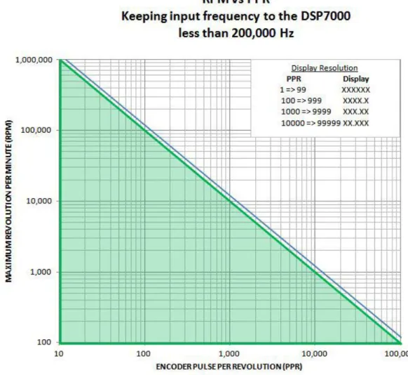
Figure 3–27 RPM vs PPR Chart ...34
Figure 3–28 Encoder Menu ...35
Figure 3–29 QUAD DEG Menu ...35
Figure 3–30 AI 1 Menu ...36
Figure 4–2 Initial P Setting for Torque Control at 25% ...39
Figure 4–3 High Initial P Setting for Torque Control ...39
Figure 4–4 Initial I Setting for Torque Control ...40
Figure 4–5 Initial D Setting for Torque Control ...40
Figure 4–6 Initial P Setting for Speed Control at 25% ...41
Figure 4–7 Initial I Setting for Speed Control ...42
Figure 4–8 Initial D Setting for Speed Control ...42
Figure 4–9 Ramp Down Low I ...43
Figure 4–10 Ramp Down High I ...44
Figure 4–11 Ramp Down Dynamic I ...44
5. alarm system Figure 5–1 Normal Condition “Energized Relay” ...45
Figure 5–2 Alarm Condition “De-Energized Relay” ...45
Figure 5–3 Typical Application ...46
Figure 5–4 Alarm Enable/Disable Menu ...46
Figure 5–5 Max Power Menu ...47
Figure 5–6 Power -OL- Display ...48
Figure 5–7 Power Alarm Display ...48
Figure 5–8 Global Power Alarm Setup ...48
Figure 5–9 Global Power Alarm Disply ...49
Figure 5–10 Speed Alarm Setup Menu...49
Figure 5–11 -OL- Speed Alarm Display ...50
Figure 5–12 Over Speed Alarm Message Display ...50
Figure 5–13 Torque Alarm Setup Menu ...51
Figure 5–14 -OL- Torque Alarm Display ...51
Figure 5–15 Over Torque Alarm Message Display ...51
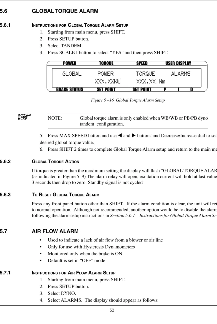
Figure 5 –16 Global Torque Alarm Setup ...52
Figure 5–17 Air Flow Alarm Setup Display ...53
Figure 5–18 Air Flow Alarm Message Display ...53
Figure 5–19 Water Flow Alarm Setup Display ...54
Figure 5–20 Water Flow Alarm Message Display ...54
Figure 5–21 External Alarm Setup Display ...55
Figure 5–22 External Alarm Message Display ...55
Figure 5–23 Temperature Alarm Message Display ...56
Figure 5–24 Electrical Alarm Message Display ...57
Figure 5–25 Clutch Alarm Message Display ...57
6. manually Controlled operation Figure 6–1 Power Units Menu ...58
Figure 6–2 Torque Units Menu ...58
Figure 6–3 Torque Control Menu ...59
Figure 6–4 Max Speed Menu ...60
Figure 6–5 Preload Function enabled ...61
Figure 6–6 Tare function enabled ...62
Figure 6–7 Torque Invert Flag Screen ...63
7. Computer Controlled operation Figure 7–1 Setup Menu ...84
Figure 8–2 IO Card Installation ...86
Figure 8–3 I/O Card Interface ...87
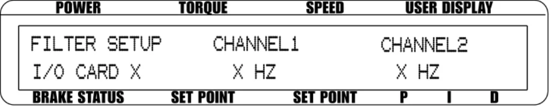
Figure 8–4 Filter Channel Setup Menu...90
Figure 8-5 Offset and Gain Setup Menu ...90
Figure 8–6 External Alarm Setup ...90
Figure 8–7 Alarm Contact Setup...90
Figure 8–8 Torque/Speed Setup ...91
Figure 8–9 Torque/Speed DAC Setup Menu ...91
Figure 8–10 GPIB Card Installation ...94
Figure 8–11 GPIB Installation ...95
Figure 8–12 Setup Menu Display ...95
Figure 8–13 RS-232 Interface ...96
Figure 8–15 Straight Through Pin-to-Pin Cable Connection ...97
Figure 8–18 Connected Instruments Window ...100
Figure 8–19 Communication with Instrument Window ...100
Figure 8–20 Query Window ...101
Figrue 8–21 Tera Term Setup Window ...101
Figure 8–22 Tera Term Licence Agreement Window ...102
Figure 8–23 Tera Term Destination Location Window ...102
Figure 8–24 Tera Term Select Components Window ...103
Figure 8–25 Tera Term Language Selection Window ...103
Figure 8–26 Tera Term Start Menu Folder Window ...104
Figure 8–27 Tera Term Additional Tasks Window ...104
Figure 8–28 Tera Term Window ...105
Figure 8–29 Terminal Setup Window ...105
Figure 8–30 Serial Port Setup Window ...106
Figure 8–31 Tera Term Window with a Command ...106
10. theory Figure 10–1 System Block Diagram...112
purpose of this manual
This manual contains all the information required for the installation and general use of the Model DSP7000 Dynamometer Controller. To ensure proper use of the instrument, please read this manual thoroughly before operating it. Keep the manual in a safe place for quick reference whenever a question arises.
who should use this manual
This manual is intended for bench test operators who are going to use the Model DSP7000 Dynamometer Controller in conjunction with any Magtrol hysteresis, Eddy-Current or Powder brake Dynamometer, Magtrol In-Line Torque Transducer or auxiliary instrumentation.
manual organization
This section gives an overview of the structure of the manual and the information contained within it. Some information has been deliberately repeated in different sections of the document to minimize cross-referencing and to facilitate understanding through reiteration.
The structure of the manual is as follows:
Chapter 1: INTRoDUCTIoN - Contains the technical data sheet for the DSP7000 Dynamometer Controller, which describes the unit and provides its technical characteristics. Chapter 2: CoNTRoLS - Description of the elements located on the front and rear panels of
the unit.
Chapter 3: INSTALLATIoN/CoNFIgURATIoN - Provides setup options available with the DSP7000 Dynamometer Controller. Illustrates and outlines the hardware connection setup and software configurations for each option.
Chapter 4: PID SETTINgS - Describes the Proportional Integral Derivative (PID) Loop and provides information on theory, setup and use.
Chapter 5: ALARM SYSTEM - Describes the new built-in alarm feature providing the user with information on how each different alarm operates along with instructions for setup and use.
Chapter 6: MANUALLY CoNTRoLLED oPERATIoN - how to run a test when the DSP7000 is used as a stand-alone unit. Includes information on setting power and torque units, torque and speed control and open loop control.
Chapter 7: CoMPUTER CoNTRoLLED oPERATIoN - how to run a test when the DSP7000 is used with a PC. Includes information on data format, programming and command set.
Chapter 8: oPTIoNAL EqUIPMENT - Information on the optional I/o cards, gPIb Interface, RS-232 Interface,
Chapter 10: ThEoRY
Chapter 11: TRoUbLEShooTINg - Solutions to common problems encountered during setup and testing.
Appendix A: INERTIA CoRRECTIoN - Describes the inertial effect on motor test data providing solutions for correction.
Appendix b: FRoNT PANEL/DISPLAY MENU FLoW ChARTS - A visual display of various setup procedures.
Appendix C: SChEMATICS - For Encoder/Switch board, Power Supply, DSP & Memory and Analog I/o.
Appendix D: ADDITIoNAL SCALE FACToR TAbLE - Provides additional scale factor values based on test instrument selection.
Conventions used in this manual
The following symbols and type styles may be used in this manual to highlight certain parts of the text:
Note: This is intended to draw the operator’s attention to complementary information or advice relating to the subject being treated. It introduces information enabling the correct and optimal functioning of the product to be obtained.
Caution : this is used to draw the operator's attention to information,
direCtives, proCedures, etC. whiCh, if ignored, may result in damage
being Caused to the material being used. the assoCiated text
desCribes the neCessary preCautions to take and the ConsequenCes that may arise if the preCautions are ignored.
Warning! THiS inTrODUCES DirECTiVES, PrOCEDUrES, PrECaUTiOnarY MEaSUrES, ETC. WHiCH MUST BE EXECUTED Or FOLLOWED WiTH THE UTMOST CarE anD aTTEnTiOn, OTHErWiSE THE PErSOnaL SaFETY OF THE OPEraTOr Or THirD ParTiES MaY BE PUT aT riSK. THE rEaDEr MUST aBSOLUTELY TaKE nOTE OF THE aCCOMPanYing TEXT, anD aCT UPOn iT, BEFOrE PrOCEEDing FUrTHEr.
GENERAL
TION
Calibration Certificate
1.2 new
features of the dsp7000
Magtrol’s new Model DSP7000 Dynamometer Controller is an upgraded version of the DSP6001, providing superior motor testing capabilities by using state-of-the-art digital signal processing technology. Designed for use with any Magtrol hysteresis, Eddy-Current or Powder brake Dynamometer, Magtrol In-Line Torque Transducer or auxiliary instrumentation, the DSP7000 both controls the dynamometer and provides digital readouts on the front panel. The features that make the DSP7000 unique include:
• Two Channels - Enables unit to support a combination of up to two testing instruments with independent or tandem configurations.
• Built-In Alarm System - To caution the user when problems occur, there are automatic electrical and temperature alarms programmed into the unit. Also inherent to the unit are optional power, speed, torque, air flow, water flow and external input alarms that become active when enabled by the user.
• Torque/Speed Analog Outputs - Able to interface with a data acquisition system • Digital Filter - Removes undesired noise from torque signals.
• Saving - Allows user to save programmed values within their configurations.
1.1
unpaCking your dsp7000
Your DSP7000 was packaged carefully for shipping. Please notify your carrier and Magtrol Customer Service if you believe your unit was damaged in shipping.
1. Save all shipping cartons and packaging material until you inspect the DSP7000. 2. Inspect the DSP7000 for any evidence of damage in shipping.
3. Make sure the carton contains the following:
DSP7000 Dynamometer Controller
Line cord
Magtrol User Manual CD-Rom USb Cord
GENERAL INFORMA TION
1.3
data sheet
DSP7000 Data SheetDSP7000 Series High-Speed Programmable
Dynamometer Controllers
MAGTROL
Features
• DSP7001 Single Channel: Low cost and easy to use
• DSP7002 Dual Channel: Enables the support of
two testing instruments with independent or tandem configurations and two fully independent control loops • Built-in Alarm System: For power, speed, torque,
temperature, air flow, water flow, electrical overload and external inputs
• High Speed Data Acquisition: Up to 500 torque and
speed points per second of both channels with time stamp
• High Quality, Easy-to-Read Vacuum Fluorescent Readout: Displays torque, speed, power, auxiliary and
PID (proportional gain, integral and derivative) values • Fast Full-Curve Data Acquisition: Free-run to
locked rotor in seconds
• Speed & Torque Operating Modes: PID settings for
exceptional dynamometer control
• Programmable Digital PID Values: Controlled and
stored via M-Test Software or controlled manually • Built-in Current-Regulated Supply: For use with
Hysteresis Dynamometer or brakes up to 1amp • Adjustable Torque Units: English, Metric and SI are
standard
• Digital Filter: Removes undesired noise from torque
signals
• Saving: Currently used configuration can be saved and
recalled at power up
• Single or Multi-point Torque and Speed Stabilized Testing: Via M-TEST 7.0 Software
• Closed Box Calibration
• Rack Mounting: 19" (482.6 mm) with handles
• Backwards Compatible: Compatible with the
DSP6001 (in DSP6001 mode) • HD5 dynamometers: Supported
• USB: Standard
• Low RPM: calculation from angle (quadrature signal)
DescrIPtION
Magtrol’s Model DSP7000 High Speed Programmable Dynamometer Controller employs state-of-the-art Digital Signal Processing Technology to provide superior motor testing capabilities. Designed for use with any Magtrol Hysteresis, Eddy-Current or Powder Dynamometer, Magtrol In-Line Torque Transducer or auxiliary instrumentation, the DSP7000 can provide complete PC control via the USB or optional IEEE-488 or RS-232 interface. With up to 500 readings per second, the DSP7000 is ideally suited for both the test lab and the production line.
aPPlIcatIONs
In the laboratory, the DSP7000’s high sample rate provides superior resolution for data acquisition and curve plotting. This allows for capturing more usable motor test data during switching, breakdown and other transitional areas of the motor test curve. For production and incoming inspection, the DSP7000 displays torque, speed and power at all times, allowing the Controller to be used as a manual stand alone unit or as part of a complete PC system.
MOtOr testINg sOFtware
Magtrol’s M-TEST 7 Software (sold separately) is a state-of-the-art motor testing program for Windows®-based data acquisition. Used with the Magtrol DSP7000 Controller, Magtrol M-TEST 7 Software provides the control of any Magtrol Dynamometer and runs test sequences in a manner best suited to the overall accuracy and efficiency of the Magtrol Motor Test System. The data that is generated by Magtrol’s Motor Testing Software can be stored, displayed and printed in tabular or graphic formats, and can be easily imported into a spreadsheet.
Written in LabVIEW™, M-TEST 7 has the flexibility to test DSP7001 - single channel
GENERAL INFORMA TION
DSP7000
Specifications
MEASUREMENT CHARACTERISTICS Maximum Torque 99,999 unitsMaximum Speed 199,999 rpm
Accuracy
Speed: 0.01% of reading from 5 rpm to 200,000 rpm Torque: 2 volt range ± 0.05% of range (±1 mV) (used on all HD Series other than HD5 Series) 10 volt range ± 0.05% of range (±5 mV) (used on all except HD Series)
ELECTRICAL CHARACTERISTICS
Voltage Requirements 85-264 VAC 50/60 Hz Power Requirements 210 VA
Fuses (5 × 20 mm) Brake: Main Power: IEC IEC 1.25 A 2.5 A 250 V T250 V T Max. Compliance Voltage 48 V DC, Brake Output
Max. Brake Output
Current 1 Amp, Calibrated that 100% OL = 1 Amp
TSC1 and TSC2 User
Power Supplies 24 Volt DC 450 mA (power supply fault protected)5 Volt DC 200 mA (internal fuse at 500 mA) ENVIRONMENT
Operating Temperature 5 ºC to 40 ºC Relative Humidity < 80%
Temperature Coefficient 0.004% of range/°C of 5 V DC for both channels
DIMENSIONS Width 19.0 in 483 mm Height 3.5 in 89 mm Depth with handles 12.4 in13.8 in 315 mm351 mm Weight 15.2 lb 6.9 kg sPecIFIcatIONs OPtIONal equIPMeNt COMMUNICATIONS RS-232 Interface
The RS-232 Interface provides backwards compatibility for older systems. 300, 600, 1200, 2400, 4800, 9600, 19200 and 115200 Baud rates are supported.
GPIB IEEE-488 Interface
The GPIB IEEE-488 Interface provides standard GPIB communications.
Optional equipment may be factory installed or purchased separately and user installed.
I/O CARD
• Torque/Speed Analog Outputs: For interface with a data acquistion system
• Analog Signal such as tachometer can be routed to PID loop
• External alarm input • Alarm relay contacts • 2 Relays
• 3 Digital inputs • 2 Digital outputs • 2 Analog inputs • 2 Analog outputs
• 5 Volts available to user fused at 500 mA. Nominal 200 mA
GENERAL INFORMA TION
DSP7000
rear PaNelsSpecifications
FrONt PaNel DSP7001 Rear PanelFor use with any Magtrol Dynamometer (Hysteresis, Eddy-Current, Powder Brake),
Magtrol Torque Transducer
• •
Connector for Model DES Power Supplies
(for WB/PB and HD 825 Dynamometers only)
USB (standard) and Optional GPIB/IEEE-488 Interface or RS-232 Interface for Connection to PC (GPIB Shown) • • •
Optional I/O Card
For use with any Magtrol Dynamometer (Hysteresis, Eddy-Current, Powder Brake),
Magtrol Torque Transducer
•
•
•
•
Optional I/O Card 1 and I/O Card 2
• •
• •
Ready for Rack Mounting
•
Displays Torque, Speed, Power and PID Values
•
• • • • • • •
Setup Menu/Open Loop Mode Set Desired Power
Units/Brake on/off
Set Desired Torque Units/Set Point Torque Speed Control/
Set Point Speed PID Scale/Adjustable PID (Proportional Gain, Integral and Derivative)
•
Select Display Format
• •
Tare
GENERAL INFORMA TION
DSP7000
System Configurations
Motor Under Test TM Torque Transducer AC Mains Hysteresis Dynamometer (HD) DSP7002 DYNAMOMETER CONTROLLER No Connection USB PC M-TEST AC Mains Motor Under Test Hysteresis Dynamometer (HD) DSP7001 DYNAMOMETER CONTROLLER USB PC M-TEST No ConnectionDSP7001 Connected to Hysteresis Dynamometer
Torque Transducer (TM)
DES Power Supply Hysteresis Brake (<1 Amp) Hysteresis Brake (<5 Amp)/ Eddy-Current/ Powder Brake OR DSP7001 DYNAMOMETER CONTROLLER USB M-TEST PC
GENERAL
INFORMA
TION
DSP7000
System Configurations
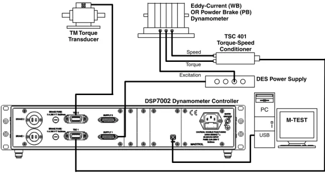
DSP7002 Connected to Eddy-Current or Powder Brake Dynamometer (WB/PB) with In-Line Torque Transducer
TM Torque Transducer USB PC M-TEST DSP7002 Dynamometer Controller Excitation Torque TSC 401 Torque-Speed Conditioner
DES Power Supply Speed
Eddy-Current (WB) OR Powder Brake (PB) Dynamometer
DSP7002 Connected to Hysteresis Dynamometer and Eddy-Current or Powder Brake Dynamometer No Connection Eddy-Current (WB) OR Powder Brake (PB) Dynamometer AC Mains Hysteresis Dynamometer (HD) Excitation Torque Speed TSC 401 Torque-Speed Conditioner DES Power Supply
Motor Under Test USB PC M-TEST DSP7002 DYNAMOMETER CONTROLLER Eddy-Current (WB) OR Powder Brake (PB) Dynamometer Excitation Torque Speed TSC 401 Torque-Speed Conditioner
DES Power Supply Eddy-Current (WB) OR Powder Brake (PB) Dynamometer Excitation Torque Speed TSC 401 Torque-Speed Conditioner
GENERAL
INFORMA
TION
DSP7000
System Configurations
DSP7002 Connected to Eddy-Current and Powder Brake Dynamometer (Tandem Setup) USB PC M-TEST Clutch (EK) DSP7002 Dynamometer Controller Transformer Powder Brake Dynamometer (PB) Excitation Torque
DES Power Supply TSC 401 Torque/Speed Conditioner Eddy-Current Brake Dynamometer (WB) Excitation Torque TSC 401 Torque-Speed Conditioner
DES Power Supply
Speed
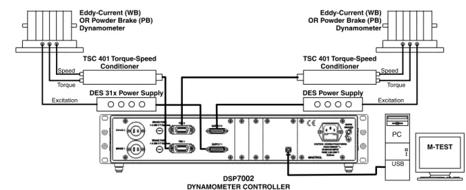
DSP7002 Connected to 2 Eddy-Current or 2 Powder Brake Dynamometers (Tandem Setup)
Powder Brake (PB) Dynamometer Eddy-Current (WB) Dynamometer Excitation Torque Speed TSC 401 Torque-Speed Conditioner
DES Power Supply Powder Brake (PB) Dynamometer Eddy-Current (WB) Dynamometer Excitation Torque Speed TSC 401 Torque-Speed Conditioner
DES Power Supply
USB PC M-TEST OR DSP7002 DYNAMOMETER CONTROLLER
The USB Driver required for communication between the PC and DSP7000 is available for download at Magtrol’s website:
GENERAL
INFORMA
TION
DSP7000
custOM MOtOr test systeM
The DSP can be incorporated into a Customized Motor Test System. These PC based, turn-key systems are custom designed and built to meet specific user requirements.
System Configurations
heavy-duty equipment rack M-TEST Motor Testing Software
WB Eddy-Current Dynamometer
DES Power Supply TSC Torque Signal Conditioner AMF Adjustable Motor Fixture Dynamometer Table HD Hysteresis Dynamometer DSP7000 Dynamometer Controller 6530 Power Analyzer keyboard drawer
side panel connectors allow for easy hook-up
space for rackmounted third-party power supply and computer
LCD monitor
GENERAL
INFORMA
TION
DSP7000
Due to the continual development of our products, we reserve the right to modify specifications without forewarning.
www.magtrol.com
MagtrOl INc MagtrOl sa Subsidiaries in:
Ordering Information
systeM OPtIONs aND accessOrIes OrDerINg INFOrMatION
DSP7001 High-Speed Programmable Dynamometer Controller - single channel
DSP7002 High-Speed Programmable Dynamometer Controller - dual channel
CATEGORY DESCRIPTION MODEL / PART #
TESTING DEVICES
Hysteresis Dynamometers HD series
Eddy-Current Dynamometers WB series
Powder Brake Dynamometers PB series
In-Line Torque Transducers TM/TMHS/TMB series
POWER ANALYZERS
High-Speed Single-Phase Power Analyzer 6510e
High-Speed Three-Phase Power Analyzer 6530
SOFTWARE M-TEST 7.0 Motor Testing Software SW-M-TEST7.0-WE
EM-TEST 2.0 Endurance Motor Testing Software SW-EM-TEST2.0-WE
POWER SUPPLIES
Closed-Loop Speed Control/Power Supply 6100
Power Supply 5200
Current-Regulated Power Supply 5210
Power Amplifier (required for HD-825 Dynamometer only) 5241
Power Supply for WB & PB Dynamometers DES 410 & DES 411
MISC. Torque/Speed Conditioner (required for connecting WB/PB Series Dynamometers to DSP6001) TSC 401
Temperature Testing Hardware HW-TTEST
CARDS & CABLES
GPIB Interface Card (PCI) 73M023
GPIB Cable, 1 meter 88M047
GPIB Cable, 2 meters 88M048
Torque Transducer Connector Cable ER 113/01
DSP7000 GPIB Card 006579 DSP7000 RS-232 Card 006578 DSP7000 I/O Card 006577 Model Number: DSP700X – X – X CHANNEL TYPE • Single Channel 1 • Dual Channel 2 COMMUNICATION OPTIONS
• none (standard USB) 0 • USB port and GPIB 1 • USB port and RS-232 2 I/O Options
• None (standard) 0 • I/O card in slot1 (7001) 1 • I/O card in slot 1 and 2 (7002) 3
GENERAL
TION
2.1
front panel
The front panel provides a power switch, eleven control buttons, a Decrease/Increase Dial, and Vacuum Fluorescent Display (VFD).
Figure 2–1 Front Panel
2.2
front panel Controls and buttons
The front panel controls and buttons, from left to right, are: • Power switch
• Ten double-function control button:
Primary Function Secondary Function
TSC DISPLAY BOTH
OPEN LOOP SETUP
BRAKE ON/OFF POWER UNITS TORQUE SET TORQUE UNITS SPEED SET MAX SPEED
P SCALE P
I SCALE I
D SCALE D
TARE
RESET TARE
Note: The TSC/DISPLAY boTh button has no function on the DSP7001 Programmable Controller.
• One single-function control button:
GENERAL
INFORMA
TION
2.2.1 Enabling SEcondary FunctionS
To enable the secondary function of the double-function control buttons:
1. Press the blue ShIFT button and release it. The word “ShIFT” appears in the display:
POWER
BRAKE STATUS SET POINT SET POINT P I D
TORQUE SPEED USER DISPLAY
0.000 W
OFF
0.000 OZ.IN
0000
0% 0% 0%
0
SHIFT
Figure 2–2 Secondary Function Menu
2. Press any control button to enable the function shown in blue letters above the button. 3. Press the ShIFT button again to exit the secondary function and return to main menu.
Note: If the brake status is oN, the ShIFT button will be ignored.
2.2.2 Enabling Saving Function
To save all current programmed settings:
1. Press the ShIFT button two times. The word “SAVINg” will appear in the display, as shown
in Figure 2–3 Saving Function Menu.
POWER
BRAKE STATUS SET POINT SET POINT P I D
TORQUE SPEED USER DISPLAY
0.000 W
OFF
0.000 OZ.IN
0000
0%
0% 0%
0
SAVING
Figure 2–3 Saving Function Menu
2. After a few seconds, the menu will automatically return to the main menu display and all configurations of the unit will be saved into a non-volatile memory.
GENERAL
INFORMA
TION
2.2.3 Howto uSE Front PanEl controlSand buttonS
2.2.3.1 Controls/Single-Function Buttons
button to use function
POWER Press I to turn power ON Press O
to turn power OFF. Turns power ON or OFF. SHIFT Press this button and release; then
press desired control button. Enables the function written in blue above control button. Press this button two times and
release. Saves current configuration of unit to non-volatile memory. DECREASE /
GENERAL
INFORMA
TION
2.2.3.2 Double-Function Buttons
button to use function
DISPLAY BOTH Press SHIFT and release; then
press this button. Displays both TSC1 and TSC2 measurments. TSC Press this button Switches between TSC1 and
TSC2 setup. SETUP Press SHIFT and release; then
press this button. Displays setup menu for dynamometer, autotune, I/O, system, and user.
OPEN LOOP Press this button Enables Open Loop mode (if brake is off).
POWER UNITS Press SHIFT and release; then
press this button. Sets desired unit of power. Press UP or DOWN button to see options. Press SHIFT to enable option.
BRAKE ON/OFF Press this button. Turns brake ON or OFF. TORQUE UNITS Press SHIFT and release; then
press this button. Sets desired unit of measure. Press UP or DOWN button to see options. Press SHIFT to enable option.
TORQUE SET Press this button. Enables adjustment of set point for torque loading.
MAX SPEED Press SHIFT and release; then
press this button. Sets the speed range of the Controller. SPEED SET Press this button. Enables adjustment of set point for
speed loading. SCALE P Press SHIFT and release; then
press this button. Turns auxiliary/torque transducer display ON or OFF. Enables adjustment of scale factors for torque and speed DAC’S. SCALE I Press SHIFT and release; then
press this button. Adjusts GPIB primary address and RS-232 baud rate. Also adjusts display contrast.
SCALE D Press SHIFT and release; then
press this button. Provides options to set maximum power, dynamometer settings (input units, maximum torque and scale factor), speed encoders and alarms.
TARE/LEFT Press SHIFT and release; then press this button.
RESET TARE/
RIGHT Press SHIFT and release; then press this button.
2.3
vaCuum fluoresCent display (vfd)
The VFD provides information about the control functions, the motor under test, and an auxiliary input device or In-Line Torque Transducer (if connected). The displays, from left to right, are:
GENERAL
INFORMA
TION
top row bottom row
POWER BRAKE STATUS (ON or OFF) TORQUE SET POINT (TORQUE) SPEED SET POINT (SPEED) USER DISPLAY
P I D
2.3.1 contraSt SEttingS
The DSP7000 is shipped with the Contrast Setting at zero (lowest) in order to prolong display life. If it is necessary to increase the Contrast for improved readability, execute the following steps:
1. Press ShIFT.
2. Press SETUP button. 3. Select SYSTEM
3. Select CoNTR until desired brightness is reached. 4. Press ShIFT 2 times to return to main menu.
Note: Make sure the lowest possible setting is used to achieve desired result. Using a setting higher than necessary may cause display segments to burn-in over a period of time, resulting in uneven illumination from segment to segment.
2.3.2 StatuS diSPlay MESSagES
message meaning
SHIFT Shift button was pressed. MAX SPEED Maximum motor RPM. UNITS Torque unit of measurement. REMOTE Remote control via PC enabled.
RAMP DOWN Decrease motor speed by increasing load on motor. RAMP UP Increase motor speed by decreasing load on motor. SAVING Saves current configuration of unit to non-volatlie memory.
RAMP DU Decrease motor speed and then increase motor speed POWER UNITS
GENERAL INFORMA TION
2.4
rear panel
The rear panel provides connectors and receptacles for connecting to appropriate equipment.
Figure 2–4 DSP7001 Rear Panel
Figure 2–5 DSP7002 Rear Panel
2.4.1 rEar PanEl inPutSand outPutS
bRAKE 1/bRAKE 2 Connect dynamometer brake cable here.Figure 2–6 Dynamometer Brake Output
bRAKEFUSE
Contains brake fuse (1A 250 VT 5 x 20 mm)
Current Regulation
-
+
(fused)+ 48 VGENERAL
INFORMA
TION
TSC1/TSC2 Connect torque signal cable here.1. FLOW/CLUTCH 2. TACH. B 3. +24 VDC 4. +24 VDC COM 5. -24 VDC COM 6. -24 VDC 7. +5.0 VDC 8. +5.0 VDC COM 9. D.P. A 10. TACH. A 11. NC 12. D.P. B 13. TORQUE COMMON 14. TORQUE SIGNAL Figure 2–7 TSC1/TSC2 Connector
SUPPLY 1/SUPPLY 2 Connect Wb/Pb DES supply for TSC1/TSC2 here.1. SHIELD (EARTH) 2. ELECTRICAL ALARM
3. SUPPLY 1-N/C / SUPPLY 2-CLUTCH 4. SUPPLY +24VDC
5. N/C 6. +24 VDC COM
7. CURRENT SET POINT (SIGNAL) 8. WATER FLOW ALARM 9. N/C
10. TEMPERATURE ALARM 11. STAND-BY 12. N/C 13. +24 VDC COM
14. CURRENT SET POINT (ANALOG OV) 15. N/C
Figure 2–8 Supply 1/Supply 2 Connector
USb Connect PC USb cable here.Figure 2–9 USB Connector
PoWER Attach power cord here. EARTh gRoUND Attach earth ground here.GENERAL
INFORMA
TION
2.4.2 oPtional io
1. Io Card 1 and Io Card 2
1. DAC 1 Analog Torque out OR user DAC 1 2. DAC 2 Analog Speed out OR user DAC 2 3. AIN1+ 4. AIN2+ 5. 5 Volts 6. External Alarm 7. DI1 8. DI2 9. DOUT1 10. Relay1 NO 11. Relay1 NC 12. Relay2 NO 13. Relay2 NC 14. T/S common 15. T/S common 16. AIN1- 17. AIN2- 18. 5 Volts Common 19. External Alarm Common 20. 5 Volts Common 21. 5 Volts Common 22. DOUT2 23. Relay1 Common 24. 5 Volts Common 25. Relay2 Common
GENERAL INFORMA TION 2.4.3 oPtional gPib 12. SHIELD 11. ATN 10. SRQ 9. IFC 8. NDAC 7. NRFD 6. DAV 5. E01 4. D4 3. D3 2. D2 1. D1 24. SIGNAL GROUND 23. ATN-COM 22. SRQ-COM 21. IFC-COM 20. NDAC-COM 19. NRFD-COM 18. DAV-COM 17. REN 16. D8 15. D7 14. D6 13. D5
Figure 2–11 GPIB Interface
2.4.4 oPtional rS-232 5. GND 1. DCD 6. DSR 9. RI 3. RX 8. CTS 2. TX 4. DTR 7. RTS Figure 2–12 RS-232 Interface
SETUP
Note: before installing the DSP7000, you should become familiar with the front and rear panels, as outlined in Chapter 2–Controls.
3.1
powering up the dsp7000
Warning! TO rEDUCE THE riSK OF ELECTriC SHOCK, MaKE SUrE THE DSP7000 iS EarTH grOUnDED BEFOrE STarTing!
3.1.1 Self-TeST
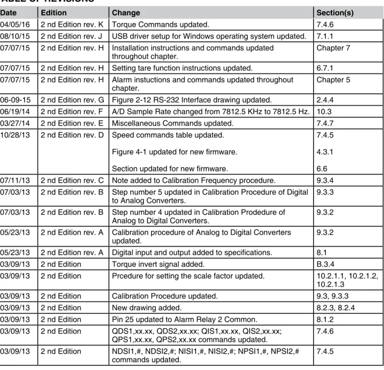
After turning the power on to the DSP7000, the display panel will show the message “SERIAL KEY PAD REV x.x” while the DSP7000 is downloading the program.
POWER
BRAKE STATUS SET POINT SET POINT P I D
TORQUE SPEED USER DISPLAY
SERIAL KEY PAD REV X.X
Figure 3–1 Program Download Display
When the program download is complete, the message “MAgTRoL MoDEL DSP700x, FW REV:xx, FPgA REV:xx” appears.
POWER
BRAKE STATUS SET POINT SET POINT P I D
TORQUE SPEED USER DISPLAY
MAGTROL
MODEL DSP700X
FW REV:XX
FPGA REV:XX
Figure 3–2 Revision DisplayIf the alarms are disabled, the following display message will appear at this time.
POWER
BRAKE STATUS SET POINT SET POINT P I D
TORQUE SPEED USER DISPLAY
WARNING ALL ALARMS ARE DISABLED
ON TSCX
SETUP
3.1.2 Main Menu
When the DSP7000 is completely powered up and ready for use, the main menu will appear on the display.
POWER
BRAKE STATUS SET POINT SET POINT P I D
TORQUE SPEED USER DISPLAY
0.000 W
OFF
0.000 OZ.IN
0000
0
0%
0% 0%
Figure 3–4 Main Menu
3.2
instrumentation setup (torque)
The DSP7000 has the ability to support a combination of up to two testing instruments with independent or tandem configurations.
Note: In the TSC1 (Wb/Pb) and TSC2 (Wb/Pb) combination, the instruments can be configured independently or as a tandem unit.
The setup of your unit will depend on which option you choose. The following sections will illustrate and outline the hardware connection and software configurations needed to begin your testing, based on your selection. For additional reference, see Appendix C: Front Panel/Display Menu Flow Charts. Each channel of the DSP7000 can support the following dynamometers:
TSC 1/TSC 2 HD WB PB TM/TF HD5
SETUP
3.2.1 DynaMoMeTer ConfiguraTion Menu
To reach the dynamometer configuration menu:
1. Turn on DSP7000 power. See Section 3.1 – Powering Up the DSP7000. 2. Press ShIFT. The word “ShIFT” will appear in the display.
3. Press the SETUP button. The display should appear as follows:
POWER
BRAKE STATUS SET POINT SET POINT P I D TORQUE SPEED USER DISPLAY
DYNO
I/O
SYSTEM
USER
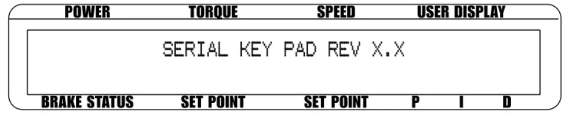
Figure 3–5 Setup Menu 4. Select DYNo. The display should appear as follows:
POWER
BRAKE STATUS SET POINT SET POINT P I D
TORQUE SPEED USER DISPLAY
MAXPOWER
DYNAMOMETER
ENCODERS
ALARMS
Figure 3-6 Dyno Setup Menu5. Select DYNAMoMETER. The display should appear as follows:
POWER
BRAKE STATUS SET POINT SET POINT P I D
TORQUE SPEED USER DISPLAY
TSCX
HD
INPUT UNITS
N.m
FILTER
NONE
Figure 3–7 Dynamometer Configuration Menu
6. Pressing the PoWER UNITS button allows selection of the preferred testing device (hD, Wb, Pb or hD5) for TSC1. Pressing the MAx SPEED button allows selection of the input units (N·m, oz·in, oz·ft, lb·in, lb·ft, g·cm, kg·cm, mN·m, cN·m). Pressing SCALE I allows selection of a filter if desired. Refer to the remainder of this chapter for more detailed instructions on setup and configuration of the different testing devices.
SETUP
3.2.2 HySTereSiS DynaMoMeTer SeTup
3.2.2.1 Hardware Connection AC Mains Motor Under Test Hysteresis Dynamometer (HD) DSP7001 DYNAMOMETER CONTROLLER USB PC M-TEST No Connection
Figure 3–8 Hysteresis Dynamometer Setup
3.2.2.2 Software Configuration
1. Turn on the DSP7000 and proceed to the dynamometer configuration menu. See Section
3.2.1 – Dynamometer Configuration Menu.
2. Press PoWER UNITS until hD is reached.
3. Press MAx SPEED until the desired input unit for TSC. 4. Press SCALE I to add a filter if desired.
5. Press ShIFT. The display should appear as follows:
POWER
BRAKE STATUS
SET POINT
SET POINT
P
I
D
TORQUE
SPEED
USER DISPLAY
TSC1
MAX TORQUE
XXXX
Figure 3–9 Hysteresis Setup Menu
6. Press ToRqUE UNITS button and use and buttons and Decrease/Increase dial to set desired max torque for TSC1.
SETUP
3.2.3 HySTereSiS DynaMoMeTerwiTH TranSDuCer SeTup
3.2.3.1 Hardware Connection Motor Under Test TM Torque Transducer AC Mains Hysteresis Dynamometer (HD) DSP7002 DYNAMOMETER CONTROLLER No Connection USB PC M-TEST
Figure 3–10 Hysteresis Dynamometer with Torque Transducer Setup
3.2.3.2 Software Configuration
1. Turn on the DSP7000. Set up TSC1 as described in section 3.2.2 - Hysteresis Dynamometer
Setup. Press TSC to switch to TSC2 setup and proceed to the dynamometer configuration
menu. See Section 3.2.1 – Dynamometer Configuration Menu. 2. Press PoWER UNITS until TM/TF is reached for TSC2. 3. Press ToRqUE UNITS until hb is reached.
4. Press MAx SPEED button and use and buttons and Decrease/Increase dial to set desired scale factor for TSC2.
5. Press SCALE I to add a filter if desired.
6. Press ShIFT. The display should appear as follows:
POWER
BRAKE STATUS SET POINT SET POINT P I D
TORQUE SPEED USER DISPLAY
TSC2
MAX TORQUE
NOMINAL SPEED
X.XXX
XXXX.X
Figure 3–11 Torque Transducer Setup Menu
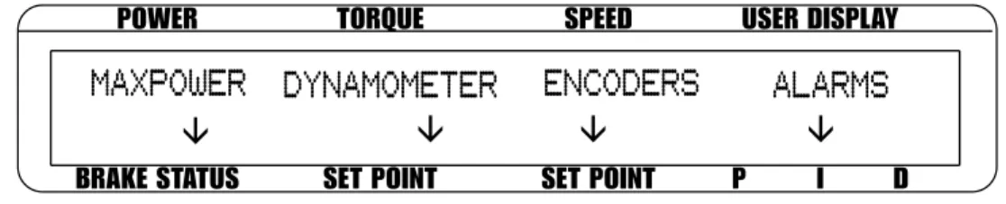
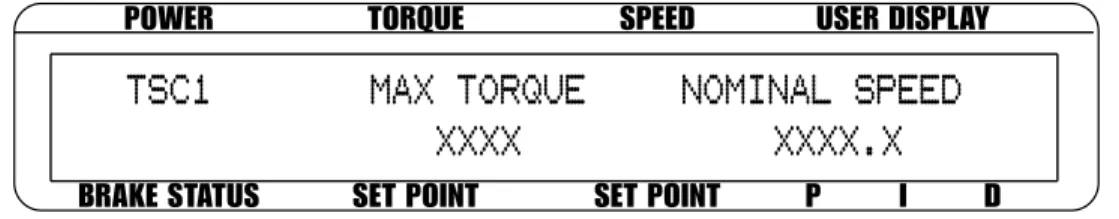
7. Press the ToRqUE UNITS button and use and buttons and Decrease/Increase dial to set desired max torque. Press the SCALE P button and use and buttons and Decrease/ Increase dial to set desired nominal speed.
SETUP
3.2.4 HySTereSiS DynaMoMeTerwiTH eDDy-CurrenTor powDer Brake SeTup
3.2.4.1 Hardware Connection No Connection Eddy-Current (WB) OR Powder Brake (PB) Dynamometer AC Mains Hysteresis Dynamometer (HD) Excitation Torque Speed TSC 401 Torque-Speed Conditioner
DES Power Supply
Motor Under Test USB PC M-TEST DSP7002 DYNAMOMETER CONTROLLER
Figure 3–12 Hysteresis Dynamometer with Eddy-Current or Powder Brake Setup
3.2.4.2 Software Configuration
1. Turn on the DSP7000. Set up TSC1 as described in section 3.2.2 - Hysteresis Dynamometer
Setup. Press TSC to swtich to TSC2 setup and proceed to the dynamometer configuration
menu. See Section 3.2.1 – Dynamometer Configuration Menu. 2. Press PoWER UNITS until Wb or Pb is reached.
3. Press MAx SPEED button and use and buttons and Decrease/Increase dial to set desired scale factor for TSC2.
4. Press SCALE I to add a filter if desired.
5.a. If using an Eddy Current Dynamometer, press ShIFT. The display should appear as follows:
POWER
BRAKE STATUS SET POINT SET POINT P I D
TORQUE SPEED USER DISPLAY
TSC2
MAX TORQUE
NOMINAL SPEED
X.XXX
XXXX.X
Figure 3–13 TSC2 Eddy-Current Setup Menu
Press the ToRqUE UNITS button and use and buttons and Decrease/Increase dial to set desired max torque. Press the SCALE P button and use and buttons and Decrease/ Increase dial to set desired nominal speed. Press ShIFT 4 times to complete the initial setup and return to the main menu.
SETUP
5.b. If using a Powder brake Dynamometer, press ShIFT. The display should appear as follows:
POWER
BRAKE STATUS SET POINT SET POINT P I D
TORQUE SPEED USER DISPLAY
TSC2
MAX TORQUE
X.XXX
Figure 3–14 TSC2 Powder Brake Setup Menu
Press the ToRqUE UNITS button and use and buttons and Decrease/Increase dial to set desired max torque. Press ShIFT 3 times to complete the initial setup and return to the main menu.
3.2.5 eDDy-CurrenTor powDer Brake DynaMoMeTer SeTup
3.2.5.1 Hardware Connection USB PC M-TEST Excitation Torque TSC 401 Torque-Speed Conditioner
DES Power Supply
Speed
Eddy-Current (WB) OR Powder Brake (PB) Dynamometer
DSP7001 Dynamometer Controller
Figure 3–15 Eddy-Current or Powder Brake Dynamometer Setup
3.2.5.2 Software Configuration
1. Turn on the DSP7000 and proceed to the dynamometer configuration menu. See Section
3.2.1 – Dynamometer Configuration Menu.
2. Press PoWER UNITS until Wb or Pb is reached.
3. Press the MAx SPEED button and use and buttons and Decrease/Increase dial to set desired scale factor. Press SCALE I to add a filter if desired.
SETUP
4.a If using an Eddy Current Dynamometer, press ShIFT. The display should appear as follows:
POWER
BRAKE STATUS SET POINT SET POINT P I D
TORQUE SPEED USER DISPLAY
TSC1
MAX TORQUE
NOMINAL SPEED
XXXX
XXXX.X
Figure 3–16 TSC1 Eddy-Current Setup Menu
Press the ToRqUE UNITS button and use and buttons and Decrease/Increase dial to set desired max torque. Press the SCALE P button and use and buttons and Decrease/ Increase dial to set desired nominal speed. Press ShIFT 3 times to complete the initial setup and return to the main menu.
4.b If using a Powder brake Dynamometer, press ShIFT. The display should appear as follows:
POWER
BRAKE STATUS SET POINT SET POINT P I D
TORQUE SPEED USER DISPLAY
TSC1
MAX TORQUE
XXXX
Figure 3-17 TSC1 Powder Brake Setup Menu
Press the ToRqUE UNITS button and use and buttons and Decrease/Increase dial to set desired max torque. Press ShIFT 3 times to complete the initial setup and return to the main menu.
SETUP
3.2.6 eDDy-CurrenTor powDer Brake DynaMoMeTerwiTH Torque TranSDuCer SeTup
3.2.6.1 Hardware Connection TM Torque Transducer USB PC M-TEST DSP7002 Dynamometer Controller Excitation Torque TSC 401 Torque-Speed Conditioner
DES Power Supply
Speed
Eddy-Current (WB) OR Powder Brake (PB) Dynamometer
Figure 3–18 Eddy-Current or Powder Brake Dynamometer with Torque Transducer Setup
3.2.6.2 Software Configuration
1. Turn on the DSP7000. Set up TSC1 as described in section 3.2.5 Eddy-Current or Powder
Brake Dynamometer Setup. Press TSC to swtich to TSC2 setup and proceed to the
dynamometer configuration menu. See Section 3.2.1 – Dynamometer Configuration Menu. 2. Press PoWER UNITS until TM/TF is reached.
3. Press ToRqUE UNITS until Wb or Pb is reached.
4. Press MAx SPEED button and use and buttons and Decrease/Increase dial to set desired scale factor.
5. Press SCALE I to add a filter if desired.
6. Press ShIFT. The display should appear as follows:
POWER
BRAKE STATUS SET POINT SET POINT P I D
TORQUE SPEED USER DISPLAY
TSC2
MAX TORQUE
NOMINAL SPEED
X.XXX
XXXX.X
Figure 3-19 TSC2 torque transducer setup menu
Press the ToRqUE UNITS button and use and buttons and Decrease/Increase dial to set desired max torque. Press the SCALE P button and use and buttons and Decrease/ Increase dial to set desired nominal speed. Press ShIFT 3 times to complete the initial setup and return to the main menu.
SETUP
3.2.7 Two eDDy-CurrenT/powDer Brake DynaMoMeTerS (inDepenDenT SeTup)
3.2.7.1 Hardware Connection Eddy-Current (WB) OR Powder Brake (PB) Dynamometer Excitation Torque Speed TSC 401 Torque-Speed Conditioner DES Power Supply Eddy-Current (WB) OR Powder Brake (PB) Dynamometer Excitation Torque Speed TSC 401 Torque-Speed Conditioner DES 31x Power Supply
DSP7002
DYNAMOMETER CONTROLLER
USB PC
M-TEST
Figure 3–20 Two Eddy-Current/Powder Brake Dynamometers (Independent Setup)
3.2.7.2 Software Configuration
1. Turn on the DSP7000. Set up TSC1 as described in section 3.2.5 Eddy-Current or Powder
Brake Dynamometer Setup. Press TSC to swtich to TSC2 setup and proceed to the
dynamometer configuration menu. See Section 3.2.1 – Dynamometer Configuration Menu. 2. Press PoWER UNITS until Wb or Pb is reached.
3. Press MAx SPEED button and use and buttons and Decrease/Increase dial to set desired scale factor for TSC2.
4. Press SCALE I to add a filter if desired.
5.a. If using an Eddy Current Dynamometer, press ShIFT. The display should appear as shown
in Figure 3–13 TSC2 Eddy-Current Setup Menu. Press the ToRqUE UNITS button and use
and buttons and Decrease/Increase dial to set desired max torque. Press the SCALE P button and use and buttons and Decrease/Increase dial to set desired nominal speed. Press ShIFT 2 times to return to the setup menu. The display will appear as follows:
POWER
BRAKE STATUS SET POINT SET POINT P I D
TORQUE SPEED USER DISPLAY
DYNO
I/O
SYSTEM
USER
TANDEM
SETUP
5b. If using a Powder brake Dynamometer, press ShIFT. The display should appear as shown
in Figure 3-14 TSC2 Powder Brake Setup Menu. Press the ToRqUE UNITS button and
use and buttons and Decrease/Increase dial to set desired max torque. Press ShIFT 2 times to return to the setup menu. See Figure 3-21 Tandem Setup Menu.
6. Press PoWER UNITS to select tandem. 7. The menu will appear as follows:
POWER
BRAKE STATUS SET POINT SET POINT P I D
TORQUE SPEED USER DISPLAY
IS THIS A TANDEM CONFIGURATION
XXX
Figure 3–22 Tandem Configuration Menu 8. Press the SCALE I button until the menu says “No”.
9. Press ShIFT 2 times to complete the initial setup and return to the main menu.
3.2.8 Two eDDy-CurrenT/powDer Brake DynaMoMeTerS (TanDeM SeTup)
3.2.8.1 Hardware Connection Powder Brake (PB) Dynamometer Eddy-Current (WB) Dynamometer Excitation Torque Speed TSC 401 Torque-Speed Conditioner
DES Power Supply Powder Brake (PB) Dynamometer Eddy-Current (WB) Dynamometer Excitation Torque Speed TSC 401 Torque-Speed Conditioner
DES Power Supply
USB PC M-TEST OR DSP7002 DYNAMOMETER CONTROLLER
Figure 3–22 Two Eddy-Current/Powder Brake Dynamometers (Tandem Setup)
Note: This particular tandem configuration is only applicable to a Wb-Wb or Pb-Pb combination.
SETUP
3.2.8.2 Software Configuration
1. Turn on the DSP7000. Set up TSC1 as described in section 3.2.5 Eddy-Current or Powder
Brake Dynamometer Setup. Press TSC to swtich to TSC2 setup and proceed to the
dynamometer configuration menu. See Section 3.2.1 – Dynamometer Configuration Menu. 2. Press PoWER UNITS until Wb or Pb is reached.
3. Press MAx SPEED button and use and buttons and Decrease/Increase dial to set desired scale factor for TSC2.
4. Press SCALE I to add a filter if desired.
5.a. If using an Eddy Current Dynamometer, press ShIFT. The display should appear as shown
in Figure 3–13 TSC2 Eddy-Current Setup Menu. Press the ToRqUE UNITS button and use
and buttons and Decrease/Increase dial to set desired max torque. Press the SCALE P button and use and buttons and Decrease/Increase dial to set desired nominal speed. Press ShIFT 2 times to return to the setup menu. See Figure 3-21 Tandem Setup Menu.
5b. If using a Powder brake Dynamometer, press ShIFT. The display should appear as shown
in Figure 3-14 TSC2 Powder Brake Setup Menu. Press the ToRqUE UNITS button and
use and buttons and Decrease/Increase dial to set desired max torque. Press ShIFT 2 times to return to the setup menu. See Figure 3-21 Tandem Setup Menu.
6. Press PoWER UNITS to select tandem. See Figure 3-22 Tandem Configuration Menu. 7. Press the SCALE I button until the menu says “YES”.
SETUP
3.2.9 eDDy-CurrenT DynaMoMeTerwiTH powDer Brake DynaMoMeTer (TanDeM SeTup)
3.2.9.1 Hardware Connection USB PC M-TEST Clutch (EK) DSP7002 Dynamometer Controller Transformer Powder Brake Dynamometer (PB) Excitation Torque DES Power Supply
TSC 401 Torque/Speed Conditioner Eddy-Current Brake Dynamometer (WB) Excitation Torque TSC 401 Torque-Speed Conditioner
DES Power Supply Speed
Figure 3–23 Eddy-Current Dynamometer with Powder Brake Dynamometer (Tandem Setup)
3.2.9.2 Software Configuration
1. Turn on the DSP7000 and proceed to the dynamometer configuration menu. See Section
3.2.1 – Dynamometer Configuration Menu.
2. Select PoWER UNITS until Wb is reached for TSC1.
3. Press MAx SPEED button and use and buttons and Decrease/Increase dial to set desired scale factor.
4. Press SCALE I to add a filter if desired.
5. Press ShIFT to get to the TSC1 Eddy-Current Setup Menu. See Figure 3-16 TSC1 Eddy-Current Setup Menu.
6. Press ToRqUE UNITS button and use and buttons and Decrease/Increase dial to set desired max torque. Press SCALE P button use and buttons and Decrease/Increase dial to set desired nominal speed. Press ShIFT 3 times to complete setup and return to the main menu.
7. Press TSC to switch to TSC2 setup and proceed to the dynamometer configuration menu. 8. Select PoWER UNITS until Pb is reached for TSC2.
9. Press MAx SPEED button and use and buttons and Decrease/Increase dial to set desired scale factor.
10. Press SCALE I to add a filter if desired.
11. Press ShIFT to get to the TSC2 Powder brake Setup Menu. See Figure 3-14 TSC2 Powder Brake Setup Menu.
12. Press ToRqUE UNITS button and use and buttons and Decrease/Increase dial to set desired max torque.
SETUP
14. Select TANDEM. The display will appear as shown in Figure 3-22 Tandem Configuration Menu.
14. Press the SCALE I button until the menu says “YES”.
15. Press ShIFT once to reach the Maximum Speed Excited Menu as shown below.
POWER
BRAKE STATUS SET POINT SET POINT P I D
TORQUE SPEED USER DISPLAY
MAXIMUM SPEED EXCITED OF PB
(CLUTCH DEACTIVATION)
XXXXX
Figure 3–24 Maximum Speed Excited Menu
16. Press the SCALE P button and use and buttons and Decrease/Increase dial to set maximum speed excited of Pb.
17. Press ShIFT 3 times to complete initial setup and return to the main menu. Note: The TSC key is disabled in tandem configuration.
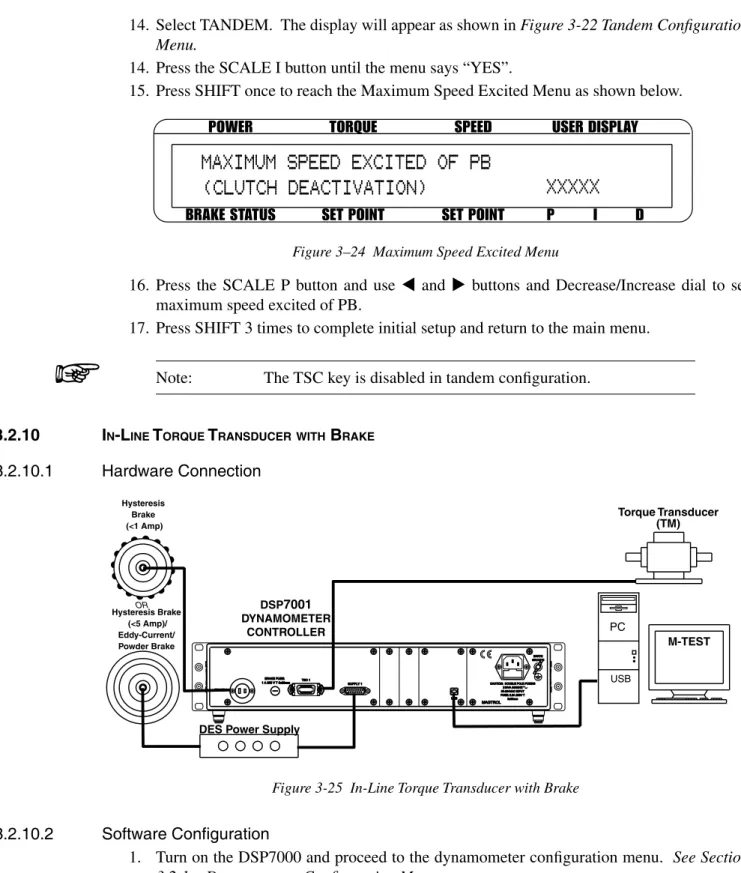
3.2.10 in-line Torque TranSDuCerwiTH Brake
3.2.10.1 Hardware Connection
Torque Transducer (TM)
DES Power Supply Hysteresis Brake (<1 Amp) Hysteresis Brake (<5 Amp)/ Eddy-Current/ Powder Brake OR DSP7001 DYNAMOMETER CONTROLLER USB M-TEST PC
Figure 3-25 In-Line Torque Transducer with Brake
3.2.10.2 Software Configuration