An Approach to Building Object Models
with UML in Embedded Systems
Mohamed T. Kimour and Djamel Meslati
Laboratory of Research on Computer Science (LRI), University of Annaba, Annaba, Algeria
The UML-based development methods of embedded sys-tems are use case-driven. In these methods, identifying objects that constitute the software system is a critical and hard task, since there is no firm guidelines. In this article, we propose a systematic approach to building object models in embedded systems. After hierarchically decomposing the system into its parts, the approach consists of firstly converting the use case into a statechart that models states of the concerned system parts and, secondly, identifying the objects from the statechart. The proposed approach bridges the gap between the outside behavioral system description, as offered by use cases and the system structure represented by the object model.
Keywords: embedded systems, object models, state-charts, UML, use cases.
1. Introduction
A strongly increasing application area for real-time systems are embedded systems, which re-ceived their name because they are embedded in a technical process. In the development of these systems, there is a growing recognition of the requirements engineering as the initial and possibly the most important activity, where the real demands to be placed on the system have to be identified and captured in a consistent and unambiguous manner 1, 2].
The most notable UML-based approaches for real-time system development are based on use cases to capture requirements 3, 4, 5, 6]. Use cases are the first artifacts to be established in the software development process. They de-scribe interactions between the system and its environment, and thus capture the functional re-quirements of the system. Functional require-ments are defined in terms of actors and use cases. In the next phases, namely analysis and
design, static and dynamic models of the sys-tem are developed. The static model defines the structural relationships among domain classes, which are covered by the UML object and class diagrams 7]. The dynamic model describes the system behavioral aspects. In particular, the use case model specifies the functionality of the system, whilst the object diagram specifies the structure of the system. The latter is used as the foundation for the design and implementation phases 8, 9].
Once the use case diagram has been built, the developer must identify the objects and classes that describe the system under development. The UML object diagram, sometimes referred to as instance diagram, is useful for exploring real world examples of objects and the rela-tionships between them. This diagram provides a conceptual description of the entities in the application domain. It complements use cases in describing requirements and provides an ini-tial architecture that first captures these require-ments. It is an important model being used at al-most all steps of the system development activi-ties. For example, behavioral diagrams, such as interaction model, cannot be constructed with-out knowing the concerned objects 10]. This is why it is fundamental to precisely identify these objects early in the system development process.
However, when developing an embedded sys-tem, it is easier and more important to start with building the object model instead of the class model 8]. Glinz et al. 13] state that class models are inappropriate when more than one object of the same class is used in a specific situation. This is the case with the embedded systems where the elements that do constitute these systems are concrete entities that can be directly mapped to objects. In contrast, classes are the templates that are used for behavioral sharing purpose and do not correspond to con-crete elements. Moreover, classes’ emphasis is put on commonalities, whereas objects in the embedded systems are often specific.
On the other hand, transition from use cases to objects is not straightforward, because there is no direct one-to-one mapping from use cases to objects. Moreover, identification of objects depends on the use cases representation. Impre-ciseness, ambiguities, and inconsistency may be present in the textual description of use cases. These description drawbacks make the object identification process difficult and usually re-sulting in unsatisfactory object or class model. Current methods that are dedicated to object and/or class identification can be classified into two categories. In the first one, the methods are based on linguistic analysis of the requirements document, which is written in a natural lan-guage. Objects and attributes correspond to the nouns, and the operations are related to verbs. In the second category, some tools that help automate the transition from use cases to class and object diagrams are proposed. However, they only can treat a very restricted form of use cases. For both, the main problem is the vague-ness, ambiguity and inconsistency of the natural language.
Therefore, transforming the use cases, which divide the system in a functional way, into objects and their properties (attributes, opera-tions), needs some practical guidelines. In this article, we propose an approach allowing object identification from statecharts that are them-selves established from use cases. Firstly, and after a hierarchical decomposition of the system into its controlled parts and controlling subsys-tem, we convert the natural language description of the use cases into statecharts, where states and events on transitions refer to the system-controlled units.
During statechart establishment, ambiguities, inconsistency and impreciseness are removed. Secondly, without any premature commitment to design, we identify objects that directly con-cern each controlled unit, and we identify ob-jects of other types according to their catego-rization. In doing so, we follow the separation of concerns principle 14, 15]. Once objects have been identified, classes to which those ob-jects belong can be determined. In this way, our approach is consistent with the Rumbaugh’s bottom-up method to discover inheritance links and organize classes 16].
It is worth noting here that statecharts are pre-cise models, easy to understand and work with. They can be used in all the phases of the de-velopment process, and hence they constitute a highly reused artifact.
Based on statecharts, our approach not only al-lows objects identification from use cases in a systematic manner, but also provides the benefit of an improved requirements specification. The identified objects, in particular those that are re-lated to the domain entities allow for enriching use cases and making them clearer, more ade-quate and useful. Furthermore, the presented method is easy to apply, integrates nicely with existing software development processes, such as the unified process 4], and does not impose an inappropriate overhead.
The rest of the article is organized as follows: section 2 describes the UML models used in our approach, namely, the use cases models, the UML statechart with its extension for rep-resenting the embedded systems behavior, and the object model with the object categorization. Section 3 presents our object identification pro-cess. In section 4, we provide an overview of the related works and compare them with our ap-proach. Finally, in section 5 the conclusion and future directions of our research are outlined.
2. Embedded Systems Modeling with UML
from the environment and/or sends commands to the controlled units appropriately.
An embedded system can, therefore, be decom-posed into its controlling subsystem and trolled units. To control these units, the con-trolling subsystem may perform computation on their status information, from which it deter-mines the necessary commands to send to these units and then updates this status information 18]. To facilitate the necessary object identi-fication, we perform a hierarchical decomposi-tion strategy. According to Glinz 13], a good decomposition is one that follows the basic soft-ware engineering principle of information hid-ing and separation of concerns. This decompo-sition will provide more clarity and preciseness to the use case descriptions and the converted statecharts, where actions and events will be related to these controlling units, such as door closed, elevator stopped in an elevator control system.
In the following, we present the use case ele-ments, the UML statechart as well as its exten-sion to effectively model the features of embed-ded systems, and finally the object categories relevant to these systems.
2.1. Use Cases
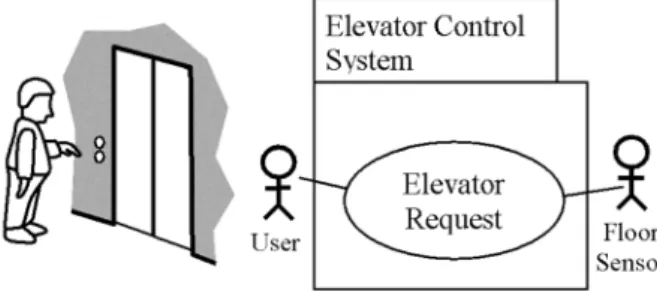
To specify the ways in which a user uses a sys-tem, a use case captures who(actor)does what
(interaction)with the system and for what pur-pose(goal) 2]. An actor is often a human user
(see example in Figure 1). In embedded sys-tems, an actor can be an external I/O device or a timer. External I/O devices and timer ac-tors are particularly prevalent in embedded sys-tems 6]. A complete set of use cases specifies all different ways to use the system, and there-fore defines all behavior required of the system. Since use cases serve as a means of communi-cation between developers and users, they are
Fig. 1.A use case diagram for an elevator request.
fundamentally written in simple text. However, their textual description presents some draw-backs such as the lack of precision and concise-ness.
On the other hand, every large system needs to be decomposed in order to make it compre-hensible and manageable. Therefore, like in RT-UML 5], the system use cases may be bro-ken down into sub(system-level)-use cases us-ing “include” and “extends”. The system use case is then realized by the set of subsystems collaborating together. Each subsystem is spec-ified in terms of its subsystem level use case.
In our approach, we are interested in the descrip-tion of a use case defined by a name, actor, pre-conditions, postpre-conditions, normal steps, and alternative steps according to Cockburn’s tem-plate 19]. To this template we have added a quality of service section in which we describe non-functional requirements(response time, se-curity, cost, accuracy, etc.). Figure 2 illustrates a typical textual description of a request elevator use case in an elevator control system.
Thus, a use case can be seen as a tuple<ucName, ucActor, ucPre, ucPost, ucSteps, ucAlt, ucQoS> with ucName a label that uniquely identifies a use case, ucActor a primary actor and the sec-ondary actors, ucPre a set of preconditions, uc-Post a set of postconditions, ucSteps a set of ordered normal steps, ucAlt a set of alternative steps, and ucQoS a set of qualities of services.
Each step in ucSteps is a tuple <sNumber, sOper>with sNumber a step number, sOper an operation(actor action(s)or system response(s)). An operation may also be a branching statement to another step. A normal step may be associ-ated with a set of alternative steps.
An alternative step can be seen as a tuple< alt-StepNumber, guardCond, altStepOper>, with altStepNumber an alternative step number and guardCond a guard condition on this step, and altStepOper an alternative operation. The latter may be divided into several sub-operations. A subset of use case steps in an automated teller machine system may be as follows:
Use Case Name: Request elevator.
Context of Use: The elevator system has many elevators that service many users at any one time, taking them from one floor to another.
Primary Actor: User, Secondary actor: Floor sensor
Precondition: User is at a floor and wants an ele-vator.
Postcondition: Elevator has arrived at the floor in response to user request.
Description:
1. User presses an up floor button. The system selects an elevator to visit this floor.
2. If the elevator is idle, the system determines in which direction the elevator should move in order to service the new request.
3. The system commands the elevator door to close. After the door has been closed, the sys-tem commands the elevator to start moving, either up or down.
4. As the elevator moves between floors, the floor sensor detects that the elevator is ap-proaching a floor and notifies the system. 5. The system checks whether the elevator should
stop at this floor. If so, the system commands the elevator to stop.
6. When the elevator has stopped, the system commands the elevator door to open.
7. If there are no other outstanding requests, the elevator stays at the current floor with the door open.
Alternatives:
1a. User presses down floor button to move down. The system response is the same for the main sequence.
2a. The elevator is moving, Go to step 4.
5a. Current floor is not in the list of the floor to visit, Go to step 4.
7a. When there are other outstanding requests, Go to step 2.
Quality of Service:
1. Elevator movement must be minimized. 2. Use case response time must be minimized. 3. Doors must be closed before starting any
ele-vator movement
Fig. 2.Textual description of the elevator request Use Case.
2.2. Statecharts
Statecharts, conceived as a visual formalism for the design of reactive systems 20], extend fi-nite state diagrams by hierarchy, concurrency, and communication, which, besides the timing constraints, are fundamental features of embed-ded systems.
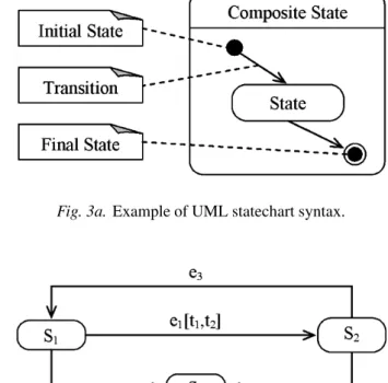
An UML statechart diagram consists of a finite number of states and transitions between states
(Figure 3a). Actions are executed either on the transition between states or on the entry into the state. A state is a stage in the behavior pattern of an entity. Modeling substates makes sense when an existing state also exhibits complex behavior, thereby motivating to explore its sub-states. States are shown as rounded rectangles.
Fig. 3a.Example of UML statechart syntax.
Fig. 3b.Example of extended UML statechart.
Although it is a valuable means for modeling embedded systems behavior, UML statechart still needs some extensions to make it both enough expressive to represent the features of these systems and enough precise to support ac-tivities like object identification, property veri-fication, test generation, etc. 21]. A detailed description and justification of these extensions is beyond the scope of this work. Figure 3b illustrates these extensions that we summarize as follows:
1. Guards can make reference to events, indi-cating whether an event has occurred. 2. Associate a set of events to a transition,
indi-cating that the transition is triggered by the concurrent occurrence of the set of events. For example, the transition from S2 to S3 is enabled only when the events e1 and e2 occur, and in the absence of the event e3. 3. Associate a time interval to a transition,
in-dicating that the transition occurs at a time
(not known a-priori) belonging to the tem-poral interval.
4. A time interval can specify a time window as an expression of event occurrence. For example, the transition from S1to S3can be triggered not earlier than t3 time units after the occurrence time of the event e1, and not later than t4 time units after the occurrence time of that event.
2.3. Object Modeling and Categorizing
At the requirements analysis level, objects are usually determined from use cases according to certain categorization. Jacobson et al. have divided the analysis space in three orthogonal dimensions: information, behavior and presen-tation 22]. This object categorization is useful to control the system’s specification complex-ity, creating a multidimensional modeling space to allow a multiple-view analysis of the require-ments with adequate semantic references. The same categorization framework was adopted by Fernandes and Machado in 8], with some em-phasis on control objects as a crucial component in any embedded system.
For the purpose of identifying objects from use cases in embedded systems, we adapt the object categories described in 6]for including coordi-nation, application logic and timer objects, too. We present this categorization as follows:
1. Interface object: handles the exchange be-tween the system and its environment. An interface object must be encapsulated in such a way that if a change is made to the ex-change between the system and its environ-ment, only the interface object has to be modified, leaving other objects unchanged.
2. Entity object: Long-living object that stores information(typically the entities in entity-relationship models). The entire behavior associated to the manipulation of that infor-mation must be included in the entity ob-ject. Typically, an entity object is accessed by many use cases.
3. Coordination object. It is an overall decision-making object that determines overall se-quencing for a collection of related objects inherent to a use case. It does not encap-sulate any computation other than the one needed for the coordination. Its main re-sponsibility is to supervise other objects in order to achieve the use case goal.
4. Application logic object: It contains the de-tails of the application logic. It is needed to hide the application logic from the data be-ing manipulated(because it is likely that the application logic could change regardless of the data).
5. A timer object: encapsulates temporal con-ditions and triggers activities in other ob-jects, periodically or at appropriate time points.
6. A control object: encapsulates appropriate computations that involve a group of entity objects or that cannot be naturally associated to other objects.
3. Object Identification Process
Based on the observation that an embedded sys-tem is a controlling subsyssys-tem and a set of controlled units, we first perform a hierarchi-cal decomposition of the system into its parts. This allows for better comprehension of the use case and facilitates determining evolution state of the controlled parts regarding the underlying use case. Afterward, we derive the statechart in an iterative and incremental way(main feature of the unified process).
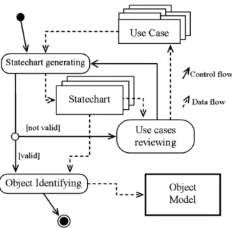
Fig. 4.Object identification process.
Figure 4 illustrates our approach to identifica-tion of objects from use cases after decomposing the system into its parts. We first need to cir-cumvent the drawbacks of the textual descrip-tion use cases and give rise to the elements that do constitute the objects, such as operations and data items. To this end, instead of directly us-ing the natural language in use case description, we transform it into a statechart, according to the appropriate procedure described in section 3.1. During this step, the use case text may be reviewed and modified in order to remove am-biguities and to exhibit more preciseness and completeness.
Second, the obtained statechart is used with the object categorization in embedded systems, to determine the objects according to the appropri-ate procedure described in section 3.2.
3.1. From Use Cases to Statecharts
In contrast to other approaches to derive state-charts from use cases, such as 3, 9, 12, 23, 24], we do not restrict the textual description of use case for capturing the requirements. Informal notations are good for recording requirements at an early stage, when great expressiveness and ease of use is more important than formal cor-rectness and executability. Table 1 describes our procedure to transform a use case text into a statechart. This procedure is structured into four iterations as described below:
Iteration
1
1. For each use case, build a graph of be-havior sequences(GBS)where each node
corresponds to a step and each edge links two nodes that correspond to the two con-secutive steps in the use case.
2. Model the normal flow first, integrate the alternative flows later and place the steps’ guards on the corresponding edges.
Iteration
2
1. Transform the GBS into a statechart. Each node is transformed into a state and the link is transformed into a transition. 2. Specify the operations of each step in the
entry of the corresponding state.
3. Specify explicitly the necessary opera-tions related to the guards in the corre-sponding states.
4. For each operation, specify the necessary state variables.
5. Specify event names and possible guards on the corresponding transitions.
Iteration
3
1. Group the states, corresponding to steps that may be performed in parallel, into a superstate.
2. If possible, decompose each state that in-corporates more than one operation, into substates such that:
Operations blocks that may be per-formed in parallel should be specified in different parallel substates,
Only one actor or one system unit should be referred in a substate, Guarded operations block should be specified in a separate substate.
Iteration
4
1. Check the statecharts to see if the follow-ing has been achieved:
States and events should be named ex-pressively and consistently,
All necessary states and transitions should be specified. As the steps are mapped to states, missing states will emerge and need to be added.
All the states in a statechart should be connected.
Check the event list created to see if all relevant events are handled, and if all the necessary operations are specified in the statechart.
2. Identify possible timing constraints and place them on the events that label the corresponding transitions.
Table 1.Statechart derivation procedure.
Iteration 1: Transforming the use case into a Graph of Behavior Sequences(GBS).
Iteration 2: Transforming the GBS into a stat-echart.
Iteration 3: Refining and restructuring the stat-echart.
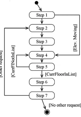
Fig. 5.Graph of the behavior sequence of an elevator request use case.
Iteration 4: Checking the statechart for internal completeness and consistency, and identifying the possible timing constraints.
In Iteration 1, a use case is transformed into a GBS (Figure 5), which is a graph where each node corresponds to a use case’s step and the edges link the use case’s ordered steps. In Iter-ation 2, we transform the GBS into a statechart
(Figure 6). The nodes become states and the
edges become transitions. In the entry of each state, we specify corresponding actor’s actions or system’s responses, according to the general format: “sAct id.Oper”, with sAct id an actor identifier to distinguish between actor’s action
(U)and system’s response(S), and Oper the op-eration name. In Itop-eration 3, we restructure the statechart in order to raise possible concurrency and hierarchy. Finally, in Iteration 4, we check the statechart for consistency and completeness. In the following section, we discuss how op-erations are determined from each use case’s step and show how to attain final version of the statechart.
Step 1: Two operations are specified: 1) user presses an up floor button, and 2) system se-lects an elevator. This last operation specifies that the system should select an elevator to visit the source floor. This description is ambigu-ous, in the sense that it isn’t precisely defined. Should the system determine any elevator, or should it determine the most suitable one? To determine the most suitable elevator in a multiple-elevators control system while taking into account the specified quality of service “minimize the elevator movement”, the system must have, not only the source floor number
(sfl) and the desired direction (dd) to be sup-plied by the user, but also some state informa-tion about each elevator(idle, moving up, mov-ing down, last visited floor).
Therefore, the first two data items should be as-sociated with the event “button pressed”. Dur-ing the statechart elaboration we uncover the ambiguity related to the described operation of “selecting an elevator” and provide the neces-sary precision by determining events and data items.
Step 2: In the entry of the corresponding state, we specify the operation “S.determineDirec-tion”.
Step 3: Two operations are explicitly specified in this step: “closeDoor” and “startMoving”. They correspond to the system commands of closing the door and starting to move eleva-tor. However, commanding the elevator to start moving should be followed by updating its sta-tus. Therefore, the missing operation “update-Status()” should be added to the corresponding state of this step. In doing so, we uncover an omission in the use case. In addition, for the sake of security, the elevator must start mov-ing not earlier than at certain time units after
the door has been closed. This important tim-ing constraint is not explicitly specified in this use case. In doing so, we uncover a possible temporal inconsistency.
Step 4: the secondary actor “floor sensor” de-tects the fact that the elevator is approaching a floor that becomes current, and notifies the
system. The system updates the current floor information of the appropriate elevator.
Step 5: The system checks if the current floor is in the list of the floors to visit by the elevator concerned. However, this operation needs ac-cess to all the pending requests, including the one that is submitted by the user at the first step. When examining the previous steps, we do not find any reference to adding this request. To un-cover this omission in the use case, we add the operation “addRequest” in the first state, after the operation “determineElevator”. This state will then comprise three operations rather than two.
Step 6: The system commands the door to open. We therefore place the operation “openDoor” in the corresponding state entry.
Step 7: The system checks if there are other requests. If so, the door must wait for a certain time before closing. This temporal requirement is not explicitly defined in the use case.
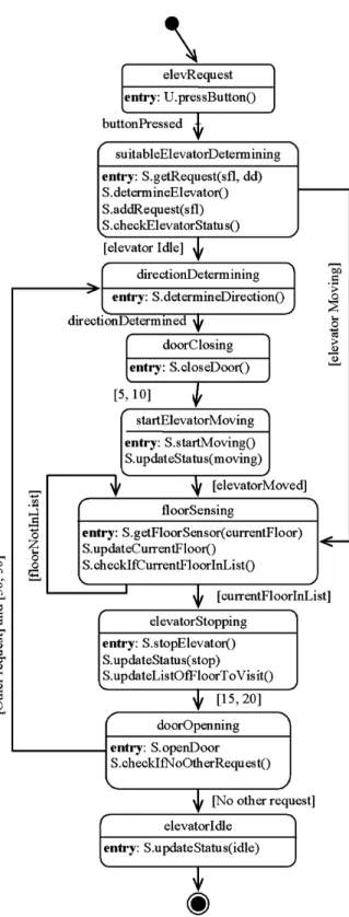
Therefore, we explicitly specify this timing con-straint as a label on the transition that starts from the door opening state and ends at the di-rection determining state. If there are no other requests, the elevator stays at the current floor with the door open. However, the information status of this elevator that becomes idle must be updated. We therefore specify the action “up-dateStatus(idle)”. Figure 7 illustrates the final version of the statechart obtained after applying iterations 3 and 4.
3.2. From Statechart to Objects
The derived statechart modeling states of the system’s controlled units, incorporates the nec-essary elements to define objects, namely, ac-tions and data items. First, for each controlled unit, we determine the necessary objects accord-ing to the procedure defined in Table 2.
Let’s apply this procedure to our resulting state-chart (Figure 7) in order to determine objects and distribute responsibilities amongst them. The controlled units identified from the state-chart are a set of elevators, a set of elevator doors, and floor sensors. For the sake of brevity, we do not consider other units such as buttons and lamps. In the following, we discuss the objects identification from the statechart: 1)We define for the whole use case, a coordi-nation object(named elevRequestCoordinator).
1. For the whole use case, define a coordinator object.
2. Define an interface object for each actor or controlled unit.
3. Define an entity object for each controlled unit that is referred to by at least one action or guard. Every action that refers to only this controlled unit should be assigned to its de-fined entity object.
4. When an action involves a group of controlled units, define a control object. Every action that involves this controlled unit set should be assigned to its defined control object.
5. Define a timer object for the action set that is triggered in specific time intervals or at a specified time point.
6. Define an application logic object to incor-porate actions that cannot be handled by any other object category.
7. Check the statechart to verify if all specified actions have been distributed to objects.
Table 2.Object identification procedure.
This object does not encapsulate any functional action. It only triggers actions encapsulated in other objects or receives signals from them.
2) For each controlled unit and actor that re-ceives and/or sends events from/to the system, we define an interface object to receive inputs from these units or actor, and/or to send out-puts or commands to them. In our example, we define interface objects for the identified controlled units(elevators, doors, and the floor sensors).
For instance, for every elevator, we define, an interface object “elevatorInterface” to receive commands (startMoving(), stopElevator()) from the system. Also, for every elevator door, we define an interface object “doorInterface” to receive commands (openDoor, closeDoor), and for the floor sensor, we define the interface object “floorSensorInterface”, to handle inter-action at every elevator approaching a floor.
Moreover, the guard condition “elevator idle” invokes an action that checks if the elevator is idle. From this guard condition, we identify the attribute “elevator status“, which may have the value “idle”. This attribute should also be encapsulated by the entity object “elevStatus-Plan”.
This entity object should provide information on whether the elevator is moving or idle, as well as on the current floor if it is at a floor or the last floor, if it is moving between floors. Furthermore, the action “addRequest()” should also be assigned to this entity object. The latter should therefore encapsulate the list of floors to visit.
As there are no computation actions, nor guards referring to the controlled units “door” and “floor Sensor”, we do not specify any entity object to these controlled units.
4)The action “determineElevator()” that selects the most suitable elevator to service the user re-quest, needs access to all elevator entity objects to use the current status of the elevators. It, therefore, corresponds to a control object named “Scheduler”.
5)Timing constraints related to door events will be handled by the timer object “doorTimer”. This object sends a timeout signals to the use case coordinator object according to the speci-fied timing constraint.
6)Finally, qualities of service mentioned in the use case text are mainly related to the opti-mization of the elevator movement. Usually, to deal with some of these non-functional re-quirements, we need an object that periodically calculates statistical parameters such as: ave-rage busy time and idle time of each eleva-tor, floor(s) where elevator(s) are very often requested. To this end, we define an application logic object “statisticalMeasure” that encapsu-lates such computations.
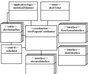
Figure 8 depicts the object model obtained from the statechart by applying the procedure de-scribed in Table 2. As previously noted, the coordinator object “elevRequestCoordinator” is an overall decision-making object that deter-mines overall sequencing for all the objects re-lated to the use case. All these objects are there-fore linked to it. Moreover, the control object “Scheduler” has links to the objects “elevSta-tusPlan”, since it accesses each elevator entity object in order to use its state information, to
Fig. 8.The object model for the elevator request use case.
select the most suitable elevator to the user re-quest. The object “statisticalMeasure” has links to the “elevRequestCoordinator” and “elevSta-tusPlan” objects.
4. Related Works
In recent years, object-oriented techniques have been employed in the development of embed-ded systems, e.g. RT-UML 5], UML-RT 3], OCTOPUS 25], Artisan Real-Time Perspective 26], etc. There are also several papers in the literature that discuss the process of building object model, e.g. 8, 9, 11, 12, 22, 27].
classes. Usually, too many objects/classes are obtained in that manner. This technique is also applied in 3, 9, 12], but with the use of auto-matic tools for natural language analysis of the use case text and the problem statements.
In 27], Rosenberg and Scott extend the ap-proach of Jacobson et al. 22] for identifying objects, using robustness analysis. However, their steps describe, in a very brief form, what needs to be done to put together the main parts of the object diagram. These describing steps do not give any type of detailed instruction on “how”.
In 8], an approach to identify objects from use cases is presented. It consists of a 4-step rule set. The approach defines the steps to obtain a holistic set of objects. Each use case is trans-formed in three objects(one interface, one data, and one control). Besides the restricted types of objects, this approach presents some limitations in a sense that it concentrates on what needs to be done rather than addressing “how” it can be done.
In 11], an approach that identifies classes is presented. It is based on goals of use cases, without descriptions. The approach produces use case entity diagrams as a vehicle for de-riving classes from use cases. However, only domain classes are identified and there is no more global technique that would allow mak-ing the transition between the two models in a systematic manner.
Most of the above mentioned tools and meth-ods begin with building classes rather than ob-jects. Our approach focuses on objects and communication between them rather than on the classes and associations between them. Since most real-time and embedded applications have a static structure, it is convenient to see the sys-tem under development as a set of communi-cating objects rather than as a set of classes with associations. To some extent, our approach complements the existing ones in the sense that, at the analysis stage, it begins with the dynamic model instead of the structural one. We be-lieve that it is better to build the dynamic model before the static one. If one begins with the dy-namic model, it is easier to identify operations, events and also attributes, which will be needed in the static model, and to obtain no more than what is needed.
5. Conclusion
In this paper we have presented a systematic ap-proach to transition from the use cases to the ob-ject model in the embedded systems area. Our approach presents a technique for converting use cases into statecharts and uses the latter as a means to identify objects. The semi-formal nature of statecharts allows for discovering the necessary objects and their properties ( opera-tions and attributes), which are needed for reali-zing the use case.
The derived statecharts help the developers in uncovering ambiguities, omissions, imprecise-ness, and inconsistency that may be present in the natural language description of the use case. In this way, while preserving the advantages of the use cases’ natural language description( ex-pressiveness and ease to use), we also allow for using existing tools to verify and prove some properties of embedded systems.
We are currently in the process of developing a semi-automatic and interactive system that helps synthesizing statechart diagrams from use cases and building the object model. In addi-tion, we are investigating the subject of modify-ing the XMI DTD to represent our extended stat-echart by means of XML documents, in order to automatically generate the interaction models.
6. Acknowledgment
We would like to thank Professor Zoubir Mam-meri from Paul Sabatier University in Toulouse
(France)whose suggestions on the first draft of this document were very helpful. Furthermore, we would like to thank the anonymous referees whose comments were useful in improving this paper.
References
1] A.G. SUTCLIFFE, N.A.M. MAIDEN, S. MINOCHA, D. MANUAEL, Supporting scenario-based requirements
engineering,IEEE Transaction on Software Engi-neering, 12(1998), pp. 1072–1088.
2] I. SOMMERVILLE,Software engineering, 6th edition, Addison-Wesley, 2001.
4] I. JACOBSON, G. BOOCH, J. RUMBAUGH,The unified
software development process, Addison-Wesley, 1999.
5] B.P. DOUGLASS,Real-time UML: Developing effi
-cient objects for embedded systems, 2nd edition, Addison-Wesley, 2000.
6] H. GOMAA,Designing concurrent, distributed, and
real-time applications with UML, Addison-Wesley, 2000.
7] G. BOOCH, J. RUMBAUGH, I. JACOBSON,The unified
modeling language user’s guide, Addison Wesley, 1999.
8] J.M. FERNANDES, R.J. MACHADO, From use cases to objects: An industrial information systems case study analysis, Proceedings of the 7th Int’l Con-ference on Object-oriented Information Systems, (2001), Calgary, Canada, pp. 319–328.
9] R.S. WAHANO, B.H. FAR, A framework for object identification and refinement process in object-oriented analysis and design,Proceedings of the 1st Int’l Conference on Cognitive Informatics,(2002), Calgary, Canada.
10] M.T. KIMOUR, Generative sequence diagrams for requirements specification in real-time systems,
Proceedings of the 2nd ACS/IEEE Int’l Conference on Computer Systems and Applications, (2003), Tunis, Tunisia.
11] Y. LIANG, From use cases to classes: a way of build-ing object model with UML,International Journal of Information Software and Technology, 2(2003), pp. 163–180.
12] D. LIU, K. SUBRAMANIAM, B.H. FAR, A. EBERLEIN, Automatic transition from use cases to class model,
Proceedings of the IEEE Canadian Conference on Electrical and Computer Engineering, (2003), Montr´eal, Canada, pp. 831–834.
13] M. GLINZ, S. BERNER, S. JOOS, J. RYSER, The ADORA approach to object-oriented modeling of software, Proceedings of the 13th Int’l Confer-ence on Advanced Information Systems Engineering LNCS, 2068(2001), Inderlaken, Switzerland, pp. 76–92.
14] G. KICZALES, J. LAMPING, A. MENDHEKAR, C. MAEDA, C.V. LOPES, J.-M. LOINGTIER, J. IRWIN,
Aspect-oriented programming,Proceedings of the 11th Int’l European Conference on Object-oriented Programming, (1997), Finland, LNCS 1241, pp. 140–149.
15] H. OSSHER, P. TARR, Using multidimensional sep-aration of concerns to(re)shape evolving software,
Communications of the ACM, 10(2001), pp. 43–50. 16] J. RUMBAUGH, M. BLAHA, W. PREMERLANI, F. EDDY, W. LARENSON,Object-oriented modeling and design, Prentice Hall, 1991.
17] T.M. CHUNG, H.G. DIETZ, Language constructs and transformation for hard real-time systems, ACM SIGPLAN Notices, 11(1995), pp. 41–49.
18] M.T. KIMOUR, Real-time object-oriented program restructuring for improved schedulability, Proceed-ings of the 8th Int’l Conference on Real-Time Systems,(2000), Paris, France.
19] A. COCKBURN,Writing effective use cases, Addison Wesley, 2001.
20] D. HAREL, Statecharts: a visual formalism for com-plex systems,Science of Computer Programming, 8
(1987), pp. 231–274.
21] V.D. BIANCO, L. LAVAZZA, M. MAURY, A formal-ization of UML statecharts for real-time software modeling, Proceedings of the Int’l Workshop on Integrated Design and Process Technology,(2002), Pasadena, CA, USA.
22] I. JACOBSON, M. CHRISTERSON, P. JONSSON, G. ¨OVERGAARD, Object-oriented software engineer-ing: A use case driven approach, Addison-Wesley, 1992.
23] H. BEHRENS, Requirements analysis and prototyp-ing usprototyp-ing scenarios and statecharts, Proceedings of the Int’l Workshop on Scenarios and State Ma-chines: Models, Algorithms and Tools, (2002), Orlando, Florida, USA.
24] S.S. SOME´, Beyond scenarios: Generating state models from use cases, Proceedings of the Int’l Workshop on Scenarios and State Machines: Mod-els, Algorithms and Tools,(2002), Orlando, Florida, USA.
25] M. AWAD, J. KUUSELA, J. ZIEGLER,Object-oriented
technology for real-time systems: A practical ap-proach using OMT and Fusion, Prentice Hall, 1996. 26] ARTiSAN Software Tools – Modeling Solutions for Real-Time Software and Embedded Systems Development.http://www.artisansw.com, last visited July 2004.
27] D. ROSENBERG, K. SCOTT, Use case driven
ob-ject modeling with UML: A practical approach, Addison-Wesley, 1999.
28] Object Management Group. Unified modeling lan-guage: superstructure. Version 2.0. OMG Adopted Specification ptc/03-08-02.www.uml.org, 2004.
Received: January, 2004
Revised: July, 2004
Accepted: July, 2004
Contact address:
Mohamed T. Kimour Laboratoire de Recherche en Informatique Universit´e de Annaba BP 12 23000, Annaba Alg´erie e-mail:[email protected]
MOHAMEDT. KIMOURis an assistant professor at the Department of Computer Science at the University of Annaba. His research inter-ests include requirements engineering and model-based development of embedded real-time systems.