INTRODUCTION
Configurators have predominately been found within Enterprise Resource Planning (ERP) and Supply Chain software packages. Therefore their usage and value have been limited to these packages and not significantly explored outside of this environment, until recently. In order to better understand this paper, it is important to first define what a configurator is and its current usage.
A configurator is a tool that can help deal effectively with certain variable aspects of manufacturing and distribution environments. A properly designed configurator can offer tremendous benefits in many different environments. Configurators are often used as very specialized and sophisticated quotation and/or order-entry points. The most common type of configurator is a product configurator, which can solve many different kinds of problems relating to special manufacturing instructions, special pricing considerations, specifications of materials, manufacturing limitations, and product limitations, as well as substitutions, additions, deletions, and modifications to products or components. Configurator usage has been increasing over the past decade as companies build products that are customer driven – “To-Order” manufacturing. Configurators can help to produce these products and shorten delivery time.
PRODUCT CONFIGURATORS
There have been two types of product configurators on the market – features/options-driven and rules-based. Features/options-features/options-driven configurators usually work at the bill-of-material level and do little more than add components to the bill-of-bill-of-material and descriptive notes to work orders. Rules-based configurators operate at a slightly higher level, allowing establishment of rules that apply to a single product or an entire family of products. This concept allows for establishment of a hierarchy of rules and enables more powerful rules to enforce or ignore other sub-ordinate rules. Using this type of rules-based configurator, a customer or a sales or service person can select a product or a family of products, and appropriate rules are applied when certain key questions requiring a decision or a choice allowed by the rules are asked. This choice or decision determines what other choices or other decisions will be required, both at the initial level and at all subsequent levels. Several companies have already realized considerable benefits from using these types of
configurators within ERP and Supply Chain packages; however, a key component has been missing in this model--integrating and re-using information in CAD/CAM and other vital systems in which data are collected and stored.
One of the great disappointments with CAD/CAM has been the difficulty of re-using CAD data. Use of CAD/CAM was expected to significantly improve productivity. Many of the benefits were expected to result from the re-use of data, but it has been difficult to achieve these benefits. Once CAD information has been created and used, it is often stored and forgotten. It's very difficult to re-use it because the geometric information is very specific and part of a complex assembly and component data structure, so users must know exactly what they are looking for. In addition, each CAD and related drawing file has to be opened to locate the necessary content information to see if it is re-usable. Even if the basic
geometry file can be found, it's difficult to find all the related information. Rather than waste time on what is nearly always a fruitless search, most people just don't bother to try to re-use CAD or CAM data.
RULES&REUSE-BASED CONFIGURATOR
In order to incorporate this missing link into a rules-based product configurator, Nainesh Rathod and his team at Imaginestics, an I/T company based in West Lafayette, Indiana, U.S.A, along with Barker Company of Keosauqua, Iowa, U.S.A, a market leader in refrigerated, non-refrigerated, and hot display cases for the supermarket, convenience store, and food service industries, began to put theory into practice in mid-2002 with the rules&reuse-based configurator. The basic premise for this theory is to re-use existing information to avoid the cost and time of the process of repeating a task that has already been carried out. Because almost 95% of Barker Company’s customer orders tend to be custom, Barker proved to be a perfect environment to apply the idea and see this configurator in production. In addition, the team anticipated several side benefits:
• If an existing part can be re-used, there is no need to go through the wasteful process of re-designing the part, re-designing the process to make and support it, simulating performance, re-developing tools, waiting for prototypes, etc. By re-using an existing part, time and money is saved, and quality is guaranteed.
• Also, since a new part number is not needed, overhead is not increased, and there is no need to extend part files, to find additional storage space, or to allocate additional working capital for holding costs.
• Because there are fewer parts, it is easier to locate existing parts, so access times can remain manageable. The exact figure depends on the specific industry and part, but the creation of a single new part, including all the activities and overhead it engenders, is generally put at several thousand dollars. If creation of a new part can be avoided, time and money are saved.
• As re-use of existing information doesn't require any development time--everything has already been developed--it can greatly reduce development cycles. Whether the
engineering change metric in use is the number of engineering changes, or engineering change cycle time, re-use of information will have a positive effect. As the information has already been used and can be expected to be correct, there should be no need for engineering change.
• As the information exists and is well defined, the corresponding parts should be perfect and there should be no scrap.
• By re-using some existing designs, less investment will be needed for the development of new designs. As there will be fewer designs, and fewer changes to designs, it will be possible to reduce the overhead costs associated with managing, storing, copying and communicating designs. Costs and time cycles will be reduced in all areas where information can be re-used. All sorts of information can be re-used. Some of this information will define parts, some will define the processes to make these parts, and some will define the relationships that link parts to products. It will also be possible to re-use information such as the engineering workflow structure.
• As companies move to product-family oriented business units, they will re-use more and more parts in their products. The ability to use information underlies the ability to re-use parts. Those companies seeking to differentiate through customization will need to re-use information supporting the common parts used in customer-specific products. The rules&resuse-based approach was considered because most discrete manufacturing companies, regardless of how complex or custom their product line is, usually build products or components that they have previously built before. Research shows that sixty percent of the time, new custom part requests include assembly or parts that are similar to something previously made or requiring minor modification.
BARKER IMPLEMENTATION
Prior to the implementation of the rules&reuse-based configurator (i-config), the entire manufacturing process at Barker Company was flow-charted and analyzed. It was decided that the order-entry process currently performed in MRP, which is Symix, was to be integrated to capture the job number and customer directly.
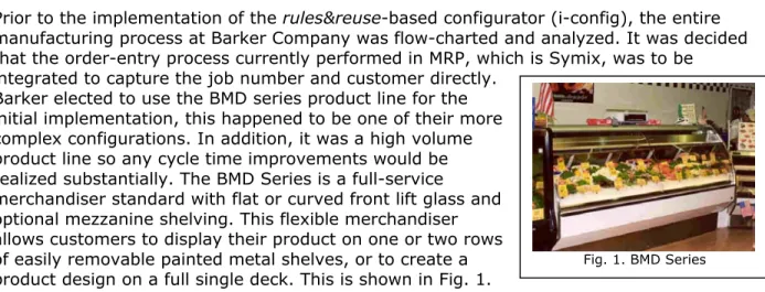
Barker elected to use the BMD series product line for the initial implementation, this happened to be one of their more complex configurations. In addition, it was a high volume product line so any cycle time improvements would be realized substantially. The BMD Series is a full-service
merchandiser standard with flat or curved front lift glass and optional mezzanine shelving. This flexible merchandiser allows customers to display their product on one or two rows of easily removable painted metal shelves, or to create a product design on a full single deck. This is shown in Fig. 1.
RULES MATRIX
A fully customizable rules matrix that allows companies to define their unique environment and special allowable customer configurations drives the i-config engine. These rules are established in easy-to-use Microsoft Access, since most companies are familiar with it. The matrix also gives companies the greatest
amount of flexibility as their business and manufacturing environment changes. However, the i-config data repository can be either Oracle or MS SQL. At Barker, three rules matrices were designed to define the product and unique customer configurations.
Parameter Rules Matrix – Parameter rules are broken into control (global) and local variables. Control variables are
parameters such as length, depth, height, which are global in nature and affect the overall dimension of the product. Local variables are more specific to a
component, such as a type of finish, which defines the thickness variable. Any allowable size configurations or
limitations were established for each assembly and component options in this matrix, some of which is shown in Fig. 2. All available assemblies and their respective component and feature options were defined in this matrix.
Assembly/Component Relationship Rules Matrix – The assembly and component rules were established in this matrix. The layout of this matrix is shown in Fig. 4. The assembly and the available components were entered in an indented bill-of-material type of a chart. Each assembly configuration contains all
Fig. 1. BMD Series
Fig. 2, Parameter Rules Matrix
available subassemblies and their respective components. Material Rules Matrix –
The properties for all available materials and the type of finish were established in this matrix, along with the component or feature that the user had options to select. Local variables such as thickness of the finish and material density were assigned in this matrix, some of which is shown in Fig. 3.
DESIGN FOR REUSE (DFR)
Parallel to the definition of the rules matrix, solid models were created in CAD for the BMD series using Solid Edge, from EDS. Careful planning and considerations were used on the CAD solid modeling, as this was key to
successful implementation of the rules&reuse approach. The CAD solid parts were designed using sketches, as these provided the greatest flexibility and control of the models
programmatically from the i-config engine. The sketch entities defining the control (global) variables and local variables were given unique variable names and linked throughout the assembly-component design, using the rules matrix definitions. All available components and their related drafting files were modeled using Solid Edge. Meta-data information was
also linked to title block and revision block fields in drafting files, such as job number, designer, customer & build date.
The concept of master and production shelf was implemented. Master shelf is made up of a directory structure that contains Barker’s standard assemblies and component CAD files, all modeled in Solid Edge. Production shelf is a directory structure where new and existing jobs with their respective CAD configuration files, including drafting and CAM files are stored. In addition, the CAD part, drafting, and CAM file numbering standard were established early in the design and modeling phase.
USER INTERACTION
Using i-config’s Java Server Pages’ (JSPs) front-end architecture, the user interfaces were designed according to Barker’s needs. The interface that the user interacts with is shown in Fig. 6. The job number and customer fields can either be entered or selected from the joblist, which is directly retrieved from the MRP system. The build date was a required entry and critical to Barker’s environment, as it determined when the modifications were allowed.
Fig. 3, Material Rules Matrix
Four options were established for a New Job. The first option is to “Create a job,” which allows users to select a specific product line. The next option is “Same as existing job number with no change,” which is used if a job number is known. The third option is “Same as existing job number with change,” which is used if a job number is known, however, the user wishes to make minor modifications. The final option is “Replacement parts - existing job number,” which is used if the new order is simply a replacement
part for an existing job.
Once a new job is selected on the previous screen, a configuration screen is displayed, as shown in Fig. 7. This screen allows a Barker customer service or manufacturing liaison to select the product
configuration and the available
options. It also allows users to deviate from this standard configuration if a custom part is to be added or created from an existing component.
Upon satisfactory selection on the configuration screen, a product
structure of the selected
configuration is displayed, as shown in Fig. 8. In addition, the product structure also shows material options available for selection of lower level parts. If a particular component needs to be custom CAM’d, a checkbox is shown next to the component. The user can
preview the CAD Solid Model, view the summary of the configuration selection, or commit the job. Fig. 6, Initial Selection
At this point i-config searches the database for an existing configuration that matches the user-selected configuration. If a
configuration is matched to other existing jobs, but custom parts were made in those other jobs using the standard parts, then the screen shown in Fig. 9 is displayed to enable the user to select these custom parts. If the configuration did not match any existing jobs and no parts were matched, or if the configuration matched an existing job, however all standard parts were used with no modification, then this screen is skipped.
The final screen shows the matched and un-matched parts and their respective draft and CAM files. At this point the user has several options, such as viewing the final CAD assembly, each individual part/component, draft files, or stock and order status. If a CAM file is found, then it shows up on this screen indicating that it has already been machined and the related files can be re-used. The stock and order option allows users to see which parts are order parts or stock parts. This helps the user create a manufacturing order sheet.
At this point a job folder on the production shelf has been created with all the CAD Solid Models and draft files. If matches have occurred, then a link has been established in the database and the parts have not been re-created.
I-CONFIG ENGINE
The i-config engine interacts with the user interface customized for Barker and conducts several operations behind the scene. It first interfaces with the three rules matrices to allow proper selections and drive subsequent screens depending on the configuration or options selected. Upon committing the configuration selection, the i-config engine at Barker
searches the i-config database and creates and modifies the standard CAD solid models and draft files from the master shelf. If no matches are found, the i-config engine creates a new job folder on the production shelf with new part numbers for both the model and draft files. If matches are found, then the engine sets up links within the database so redundant model files are not created; however, a new draft file is always produced because the meta-data information in the title block, which contains the job number and customer name, is always unique. The engine also has an interface to the CAD application via API’s (Application Protocol Interface). This allows the engine to modify the control and local variables in the CAD models and assemble the appropriate files based on the configuration selected in the user interface. If CAM files exist in the job directory for the matched model file, then the engine finds and records this information in the database and displays it on the final screen.
Fig. 9, Standard versus custom selection
BENEFITS
Several of the initial goals were met with the rules&reuseapproach. Some of these were: Plan and link the information flow from customer service through manufacturing. Enable rapid and convenient information retrieval from completed jobs.
Use a configurator to drive the solid models and programmatically create likely part variations
Minimize custom programming and/or modeling. Simplify the required ERP bills of material. Minimize data storage requirements.
Minimize rework caused by recreating parts that have already been modeled. Streamline the parts numbering scheme and data paths.
Prior to the rules&reuseconfigurator, the solid modeling process at Barker was localized to the engineering design group and one step removed from the entire manufacturing
information flow. Now, not only has it simplified and automated the task of creating solid models, but also it is helping manage the process of converting diverse customer
requirements into deliverable final products. This enhanced process has seamlessly
integrated the engineering and design function into the entire product life cycle – customer service to final manufacturing and assembly.
NEXT PHASE AT BARKER
The first objective was to prove the rules&reuse configurator approach in a production environment. Upon successfully proving this approach, Barker Company and Imaginestics have entered into the next phase to optimize the CAD solid models and the rules to increase the speed at which the CAD models are created and modified by the i-config engine. In addition, plans for the next phase include adding other Barker product lines into the configurator and making them available to respective product line personnel.
Plans are also being made to integrate Microsoft Outlook Forms to the i-config engine to automatically route completed forms electronically to various departments at Barker.
SIGNS TO CONSIDER RULES&REUSE-BASED CONFIGURATOR
Barker Company was a logical site for proving the new rules&reuse-based configurator; however, other discrete manufacturing companies may be candidates for utilizing the approach explained in this paper. Here are signals that indicate significant need to consider a rules&reuse-based configurator.
1. New customer orders are sent to the engineering department 2. New customer orders contain errors such as
a. Accepting mutually-exclusive features
b. Accepting change requests with dependencies ignored 3. Orders for customized products are handled separately 4. New orders require pre-processing before order entry
5. Copies of new orders go directly to the purchasing department 6. Bills-of-material need to be created prior to order entry
7. Order entry jobs require manuals, product notes, catalogs, or accessory sheets 8. Order entry jobs require vast knowledge of products and/or accessories
10. Processing “Repeat orders” for customized products requires access to paperwork from previous orders
Reference Information
Barker Company Web Site: http://www.barkercompany.com Imaginestics Web Site:
http://www.imaginestics.com Solid Edge Web Site:
http://www.solidedge.com/ Contact Information Barker Company Pat McMahon 703 Franklin Keosauqua, IA 52565 [email protected] 319-293-3777 Imaginestics, LLC Nainesh Rathod Purdue Research Park 1220 Potter Dr., Suite 124 West Lafayette, IN 47906
[email protected] 765-464-1700 x 21
Server configuration at Barker
The computer server hardware and application configuration utilized for i-config at Barker is as follows:
Hardware
Pentium III 1.2 GHz Server 1 Gigabyte RAM
60 GB HD
Application
Microsoft Windows 2000 Server Microsoft Access
Oracle 9i