An Improved Non-Linear Physical
Modeling Method for Brace Elements
A. Davaran
1;and M. Adelzadeh
1Abstract. In this paper, the cyclic nonlinear behavior of a brace element has been modeled. A brace element is modeled as two elastic beam-column segments, which are connected to each other via a plastic hinge. The far ends of the element are hinged. By a suitable combination of the isotropic and kinematical hardening rules of plasticity, the nonlinear axial force-displacement relation for a beam element has been derived. So, the strain hardening, strain softening, tangential modulus of elasticity and Bauschinger eects are taken into account. This model shows good agreement with experimental results that have been reported in other research works.
Keywords: Bracing; Nonlinear; Work hardening.
INTRODUCTION
Concentric bracing is commonly used as a lateral load resisting system in steel structures. This system is comprised of brace elements. A brace element is a beam-column element, which buckles in compression with a subsequent plastic zone (ideally plastic hinge) formation in its mid-span. The plastic hinge rotation in compression or tension, as well as the extensional plastic deformation of the element, causes a part of the induced external energy to be dissipated per loading cycle. The precise cyclic behavior of a brace element is not yet well understood and many factors, such as buckling and post-buckling behavior, Bauschinger eect, local buckling and low- cycled fatigue failure, complicate the precise analytical prediction of the cyclic behavior. Nevertheless, the growth of more powerful seismic codes, e.g., performance-design meth-ods require that the inelastic behavior of this type of structure can be simulated as accurately as possible.
Many analytical methods have been developed for predicting the cyclic behavior of brace elements, which can be classied into three groups:
a) Finite element method;
1. Faculty of Civil Engineering, University of Tabriz, P.O. Box 5166616471, Tabriz, Iran.
*. Corresponding author. E-mail: [email protected] Received 7 September 2006; received in revised form 17 February 2007; accepted 23 June 2008
b) Phenomenological method; c) Physical modeling method.
The nite element method can provide a more precise response of the brace element, but it is very time consuming for use in the practical analysis of structures with so many elements [1].
The phenomenological method mimics the cyclic behavior of the brace element by using simple relations that are successfully used for the analysis of large-scale structures. The main shortcoming of this method is that many experimental parameters are to be adjusted to simulate the cyclic behavior of each brace element.
The variation of these parameters seriously changes the nal behavior. In addition, the precise choice of these parameters is very tedious and a lot of experiments have to be done for every specic case.
On the other hand, the physical model theories attempt to present the geometric and material nonlin-ear behavior of the brace element via the physical and geometrical properties of the member such as: Cross sectional area, moment of inertia, eective length and plastic modulus. Examples of these methods can be viewed in the works of Nilfrooshan [2] and Nanaka [3]. Most of these methods have some restrictions, for instance:
a) The plastic behavior is concentrated at a point called the plastic hinge, so the distributed plasticity is ignored;
b) The material is assumed to be elastic-perfectly plastic with no Bauschinger eect;
c) The compressive force reduction in subsequent cycles is not taken into account;
d) The end condition is only hinge-hinge.
The following methods have been developed to modify parts of the above-mentioned faults.
For example, Ikeda and Mahin [1] and Remenikov and Walpole [4] could enter the Bauschinger eect, and deterioration of the postbuckled compressive force has been revealed in their models.
Recently, El-Tawil and Jun Jin [5] proposed a beam-column brace element with the capability of distributed plasticity simulation and work hardening material modeling. Their model also can include any kind of end conditions.
In this paper, based on the method developed by Remennikov and Walpole [6], work hardening rules have been modied, so that good agreement between experimental and modied analytical methods has been attained.
The experimental results gained from the work of other researchers [7,8], have been used as a bench mark to validate the obtained results.
GENERAL CHARACTERISTICS OF BRACE ELEMENT CYCLIC BEHAVIOR Every cycle of the nonlinear load-displacement re-sponse of a brace element is separated into dierent zones, corresponding to the dierent deected positions of the element.
A complete hysteretic cycle of an element is
divided to four general zones of elastic, plastic, axial yielding and a post-buckled elasto-plastic zone (see Figure 1). It should be mentioned that the word \elastic" or \plastic" pertains to the plastic hinge state, while the word \yield" relates to the state of the beam segments.
The beam segments are assumed to behave elas-tically, with the exception of cases wherein the element is axially extended beyond the yield point. Other than the aforementioned tensile yielding case of beam segments, the rest of the plastic behavior is assumed to be revealed in mid-span plastic hinges only. The elastic zone can be separated into a shortening zone (ES1, ES2) and an elongation zone (EL1, EL2). In the shortening zone, both the length and axial force of the member are decreased. The converse situation is occurred in an elongation zone. Similarly, the plastic zone is separated into plastic contraction P 1 and plastic elongation P 2.
BASIC EQUATIONS
For simplicity, basic equations are derived for the right half of a brace member, as shown in Figure 2.
The deected shape of the right half of the brace is obtained by solving the basic beam-column equations:
EIIV + P 00= 0: (1)
By solving Equation 1 and considering the boundary conditions, the plastic hinge moment- rotation relation-ship can be written as [9,10]:
M = (k)ELtI; (2)
Figure 2. Typical geometry of model.
where: k2=jP jL2
EtI ; (3)
(k) = (
k 2tan k2
P < 0
k
2tanh k2
P > 0 (4)
From Equation 2, the plastic hinge rotation can be expressed as:
= LM
(k)EtI: (5)
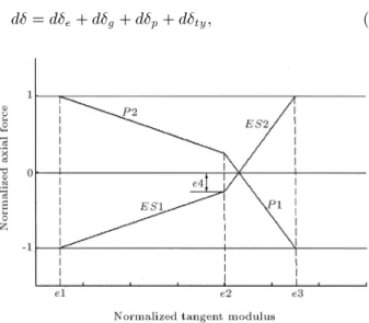
The tangent modulus of elasticity Etvaries in dierent
zones and is determined based on the experimental data on stub columns. In this paper, Et is prepared
based on an empirical model that has been used by most researchers, as shown in Figure 3.
The total axial deformation increment is assumed to consist of four components:
d = de+ dg+ dp+ dty; (6)
Figure 3. Empirical model of tangent modulus of elasticity.
where:
e is the elastic axial deformation;
g is the geometric shortening deformation;
p is the plastic hinge deformation;
ty is the tensile yield deformation.
The elastic axial deformation increment can be expressed as:
de=EL
tAdP: (7)
The expression for the geometric shortening deforma-tion is:
g= 12
Z L
0 (
0(x))2dx: (8)
The incremental form of Equation 8 can be expressed as:
dg= L2
dh(k) dk dk dP 2
L + 2h(k) d dP ; (9) h(k) = 8 > > < > > : sin k k +1
16 cos2 k
2 P < 0 sinh k
k +1
16 cosh2 k
2 P > 0
(10) The plastic hinge deformation increment is evaluated via the ow rule, according to Druker's postulate [11]:
dP = d:fP; dP = d:fM; (11)
where fP and fM denote the derivatives of yield
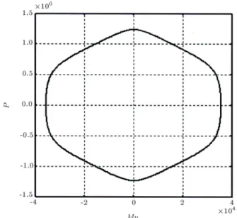
function f, with respect to P and M. For a uni-axial stress state, the yield surface can transform into function inter-relating stress resultants, i.e. axial force P and bending moment M. This function is usually demonstrated in the form of an interaction curve. The P M interaction curves can be generated for any cross-section using simple beam-column theoretical formulas [9].
For example, the interaction curve for the 150UC30 section is shown in Figure 4, which has been used in one of the examples.
From Equation 11, the plastic hinge displacement takes the form:
dp= ffP M
dp
dPdP: (12)
From Equations 7, 9 and 12, dP can be dened as follow:
dP = Ktd; (13)
Kt=
EtA
1+EtAL2
h
dh(k) dk dPdk
2
L+2h(k)dPd
i
+EtAffMP ddPp
: (14)
Figure 4. Interaction curve for the 150uc30 section.
Ktis the tangent stiness coecient, in general, and it
should be noted that, if the brace behaves under elastic loading or unloading conditions, the terms pertaining to the plastic state in Equation 14 must be skipped. It should be mentioned that an initial imperfection, in the form of an initial , is required for starting the numerical procedure.
A general form of hysteretic curve resulting from Equation 14, without considering the hardening eect, is shown in Figure 5. This curve has been obtained for a brace with an H-shaped cross-section which will be fully discussed in the next section.
From Figure 5, it can be seen that this model accurately shows a decrease in buckling load capacity, especially in the second cycle, as compared with the rst cycle.
HARDENING OF MATERIAL
In this article, a combination of kinematical and isotropic hardening rules, i.e. a mixed hardening rule, is explained to simulate the hardening behavior of material to obtain a compliance with experimental results. Each kind of hardening rule is briey explained in the following sections.
ISOTROPIC HARDENING
The isotropic hardening rule is the simplest hardening rule, which is recognized via identical and independent strain hardening, both for tension and compression paths, without revealing the Baucshinger eect. Con-sequently, the yield surface expands uniformly during hardening.
Suppose that the initial yield surface is described
Figure 5. Analytical cyclic behavior of a brace element.
by:
f(P; M) = 0: (15)
By the aforementioned denition, the isotropic harden-ing can be expressed as:
f(P; M) () = 0: (16)
Usually, there are two measures of hardening, which have been specied as follows [12]:
1. On the basis of the plastic strain:
= "p=Z d"p: (17)
2. On the basis of the total plastic work:
= Wp=Z d"p: (18)
Considering both denitions, it appears that strain hardening is simpler to use, but the work-hardening hypothesis is more general.
KINEMATICAL HARDENING
In the kinematical hardening model, it is assumed that during the process of plastic loading the yield surface translates in the stress space, but its shape and size remain unchanged.
This is motivated by the Bauschinger eect, which occurs in the uni-axial tension - compression behavior of steel materials.
In this model, the yield surface takes the following form:
f(P P; M M) = 0; (19)
in which = (P; M) represents the center of the
There are several methods to determine . In the present study, the Prager method has been used.
According to the Prager method, the increment of is proportional to the increment of the plastic strain as follows:
d = cd"p; (20)
where c is a material constant.
By assuming this model, the yield surface keeps its original shape and size, but moves in the direction of the plastic strain rate (or increment), which is normal to the yield surface at the loading point, due to the normality condition. By virtue of the measured response of a braced element, the real plastic behavior seems to be well established with a combination of both hardening rules at the plastic hinge. From a computational point of view, the derivatives of yield function, f, i.e. fP and fM, in Equation 14, are
calculated via the instantaneous state of the yield function, which is altered by Equations 16 to 20. As a special case of no hardening, the elastic perfectly plastic behavior governs and the yield function and its derivatives remain constant overall in the analysis. COMPARISON OF ANALYTICAL AND EXPERIMENTAL DATA
To investigate the accuracy of the theoretical model prediction, a computer program has been written, based on the presented formulation. The experimental data of two brace elements are extracted from valid references and are compared with the analytic results of this paper. These tests have been carried out by Popov et al. and Walpole- Leowardi [13] on tubular and wide ange sections, respectively.
Brace Element Investigated by Walpole-Leowardi
A test was conducted on the pinned-pinned speci-men with a length of 2.41 m and a 150UC30 cross-section [13], having the following properties:
A = 3:795 10 3:m2; I = 5:62 10 6:m4;
E = 2 1011 Pa; F y = 3:2 108 Pa:
In Figure 6, the dashed line denotes the experimental result and the solid line denotes the analytical result.
The axial force vs plastic hinge rotation and the history of the axial force plastic hinge moment in consecutive cycles are shown in Figures 7 and 8, re-spectively. It must be noted that the dashed lines have been provided by precise scanning of the clear graphs, which are available from the mentioned reference, and then by redrawing and having them undergo special treatment using ACAD drafting tools.
Figure 6. Comparison of analytical and experimental P curves.
Figure 7. P curve.
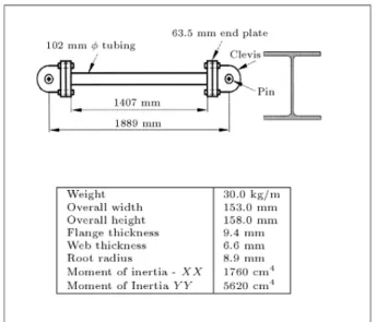
Brace Element Investigated by Popov et al. Popov et al. conducted tests on six tubular struts [7], one of which is veried here. The test specimen properties are shown in Figure 9.
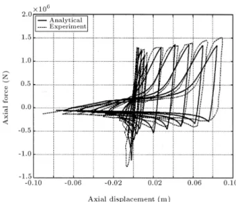
As Figure 10 shows, a good adjustment exists between experimental and analytical results. In Fig-ures 11 and 12, the P and P M cyclic curves at the plastic hinge are depicted, respectively.
CONCLUSIONS
In this paper, regarding the observed experimental re-sults of the cyclic nonlinear behavior of brace elements, the physical modeling method is further improved to obtain more adjustment between experimental and analytical hysteresis curves. Both the kinematical and istropic strain hardening rules are suitably combined
Figure 9. Speciment used in tests by Popov et al.
Figure 10. Comparison of analytical and experimental P curves.
Figure 11. P curve.
Figure 12. P M curve.
and added to a code, which is prepared in Matlab, based on the recent works of other researchers. The modied method has been applied to predict the hysteresis response of two dierent brace elements that have been studied as bench mark cases by many researchers. A reasonable agreement can be deducted by comparing the analytic and experimental hysteresis loops.
A slight discrepancy, which is observed in a few cycles, especially in the second example, can be at-tributed to local buckling and low cycle fatigue eects, which cannot yet be gained by this method. These local eects can be handled using a non-linear nite element approach.
It seems the presented method could be further improved to encompass the aforementioned eects. REFERENCES
1. Ikeda, K. and Mahin, S.A. \Cyclic response of steel braces", J. Struct. Eng., 112(2), pp 342-361 (1986).
2. Nilforoushan, R. \Seismic behavior of multi-story K-brace4d frame structures", Rep. No. UMEE 73R9, Dept. of Civil Engineering, Univ. of Michigan Ann Arbor, Mich. (1973).
3. Nonaka, T. \An elastic-plastic analysis of a bar under repeated axial loading", Int J. Solid struct., 9, pp. 569-580 (1973).
4. Remennikov, A.M. and Walpole, W.R. \Analytical prediction of seismic behavior for concentrically-braced steel systems", Earthquake Eng. Struct. Dyn., 26, pp 859-874 (1997a).
5. Jun Jin1 and Sherif El-Tawil, P.E. \Inelastic cyclic model for steel braces", Journal of Engineering Me-chanics, 129, pp. 548-557 (2003).
6. Remennikov, A.M. and Walpole, W.R. \Modeling the inelastic cyclic behavior of a bracing member for work-hardening material", Int. J. Solids Struct., 34, pp. 3491-3515 (1997b).
7. Popov, E.P., Zayas, V.A. and Mahin, S.A. \Cyclic
inelastic buckling of tubular steel braces", Report No. UCB/EERC- 0/16 (1980).
8. Remennikov, A.M. and Walpole, W. R. \Incremental model for predicting the inelastic behavior of steel bracing members", Research Report 95-6 (1995). 9. Chen, W.F. and Atsuta, \In-plane behavior and
de-sign", Theory of Beam-Columns, 1, McGraw-Hill, New York, USA (1976).
10. Timoshenko, S.P. and Gere, J.M., Theory of Elastic Stability, McGraw-Hill, New York, USA (1961). 11. Drucker, D.C., Plasticity in Structural Mechanics,
Pergamon Press, London, pp. 407-488 (1960). 12. Akhtar, S. Khan, Sujian, H., Continuum Theory of
Plasticity, Wiley-Interscience (1995).
13. Leowardi, L.S. \Performance of steel brace members", ME Thesis, University of Canterbury, Christchurch, New Zealand (1994).