Sharif University of Technology
Scientia IranicaTransactions D: Computer Science & Engineering and Electrical Engineering www.scientiairanica.com
A reliable fault tolerant attitude control system based
on an adaptive fault detection and diagnosis algorithm
together with a backstepping fault recovery controller
H. Bolandi, M. Haghparast
and M. Abedi
Department of Electrical Engineering, Iran University of Science and Technology, P.O. Box 1684613114, Tehran, Iran. Received 5 October 2011; received in revised form 2 October 2012; accepted 19 February 2013
KEYWORDS Fault detection; Fault isolation; Fault recovery; Attitude control; Hardware in the loop test.
Abstract. This paper presents a practical solution to achieve a fault tolerant attitude control system capable of Fault Detection and Diagnosis (FDD). The novelty of our proposed strategy is in the accurate modeling of satellite dynamics by the Takagi-Sugeno method. Based on this model, an adaptive observer has been utilized to achieve fault diagnosis in reaction wheels of the Attitude Control System (ACS). For this, the occurred faults in reaction wheels have been estimated using an adaptive algorithm which provides fault detection and identication abilities. Moreover, in this paper, a recovery algorithm has been utilized, combined with fault detection and identication algorithm, to provide an advanced decision support system. In this regard, for undertaking the remedial actions, a backstepping feedback linearization control law has been considered in which the estimated fault has been utilized. Accordingly, the boundedness of the attitude control error is guaranteed, despite actuators fault. The developed algorithms provide a signicant degree of autonomy to eectively handle satellite operation in the presence of ACS faults, without the ground segment intervention. Through extensive simulation results, the designed algorithms are shown to be robust and accurate. Also, designed algorithms are assessed through hardware in the loop test bed to evaluate their functions in an experimental situation.
c
2013 Sharif University of Technology. All rights reserved.
1. Introduction
The increasing complexity of satellites, exposure to space radiations and, more importantly, the limited access of satellites cause that fault event in these space vehicles be inevitable. In this regard, although the measures, such as selecting highly reliable components and conducting quality assurance process, make it possible to achieve high reliability, but mentioned strategies only cause delay in fault occurrence [1]. History of fault events in dierent missions shows thats
*. Corresponding author. Tel.: +98 21 77204040; E-mail address: mehran [email protected] (M. Haghparast)
these events have always been challenging, even in today's modern satellites. A statistical comparison based on data achieved from 1584 satellites between 1984 and 2008 indicates that 36 percent of faults are attributed to the Attitude Determination and Control System (ADCS) [2]. These events have been resulted in degradation of expected services, loss of vehicle control or, in case of total failures, catastrophic loss of mission. Accordingly, there is a need to develop fault tolerance tools in a safety critical subsystem, such as ADCS, capable of detecting, identifying and isolating any component fault.
Traditional Fault Detection and Isolation (FDI) mechanisms are based on hardware redundancy in which the required reliability is achieved by multiple
sensors and actuators accompanied by a voting sys-tem [3]. In these syssys-tems, the value that has the majority in outputs is considered as the desired output value; thus prevents the spread of fault in the system. The Above systems, despite having extensive heritage in aerospace systems, are not suitable solutions for ap-plications in which mass, power and cost are restrictive. The rapid growth of digital implementation techniques have led to a new philosophy in FDI techniques, which are known as analytical redundancy [4]. These approaches are used as a powerful alternative which do not suer from the restrictions related to mass and power. In fact, analytical methods provide the possibility of replacing the hardware replication with a management of functional or analytical redundancy constituted by the knowledge of system.
Analytical approaches which have been applied to the attitude determination and control system are categorized to model-based and data-based methods [4-7]. In this regard, by using neural networks and available data from a pulsed plasma thruster, this element has been modeled and the output dierence of the modeled element and real element has been utilized as a measure for fault detection [8]. Also the authors of [9-11] have used the above method for fault detection. Note that the capabilities of the mentioned approach are restricted only to the range of the stored data, so utilizing this method for a system such as satel-lite, which may experience unpredicted operational conditions, is risky and may lead to incorrect fault declaration. To deal with the above problem, model-based approaches have been proposed. Kalman lter-based techniques are important model-lter-based methods which have several applications in ADCS. In [12], two Kalman lters have been used for fault detection and isolation which are based on the measured outputs from gyros, sun sensor and magnetometer. Also, the prob-lems of fault detection and isolation based on Extended Kalman Filter (EKF) and Unscented Kalman Filter (UKF) have been addressed for nonlinear dynamics of satellites [13-16]. In [17], application of a bank of interacting multiple Kalman lters for detection and diagnosis of anticipated reaction wheels failures in ACS has been described and developed. Note that, the above method imposes high computational loads, since most of the main modes (dynamics) of the system should be considered in the design process. Also, the modes which are not included cannot be isolated. Kalman lter-based methods, although provide fault detection and isolation capabilities, are not robust against disturbances and uncertainties in the satellite dynamics. To resolve the mentioned problem, an Unknown Input Observer (UIO) has been used in the thrusters of a satellite named MEX to develop fault detection and isolation algorithms which are robust against disturbances [18,19]. Although these
algo-rithms are considered robust techniques against distur-bances, they have been applied only for linear dynamics of satellites. The residual generation technique based on H1 theory which has been applied for Microscope
satellite is also designed for linear dynamics [20]. In contrast, fault detection and isolation methods based on sliding mode observers are an important class of robust techniques which have been applied for nonlin-ear dynamics of satellites [21-23]. Since, these methods utilize a xed structure (related parameters cannot be updated online), a conservative upper-bound has been assumed for existing faults and uncertainties in the satellite dynamics. Another approach to compensate the eects of uncertainties and disturbances are adap-tive observers, the parameters of which, in contrast to sliding mode, can be updated online, and hence the upper bound of faults and uncertainties is estimated accurately [24,25]. In this approach, the estimated fault term is used as a measure for fault detection and isolation. Adaptive observers applied to ACS, have been designed based on linear dynamics. The scheme developed in this paper, resolve the problem of application of adaptive observers to nonlinear dynamics of satellites. To this end, satellite dynamics has been modeled using Takagi-Sugeno approach which is a new idea in the category of fault diagnosis in ACS. This approach provides the satellite dynamics approximation based on combination of local linear models in dierent operating points [26]. In this regard, by designing adaptive observer, using the obtained model, the fault occurred in the actuators can be estimated, which in addition to ensuring bounded estimation error, fault detection and identication features are also achieved. On the other hand, for compensating the fault eect and undertaking the appropriate subsequent actions, an active mechanism has been suggested, which provides reconguration possibility after fault event. To this end, for en-suring system stability before fault occurrence, back-stepping feedback linearization control law has been applied. After fault occurrence, controller structure is recongured so that the fault term identied by the adaptive observer is utilized as a compensating factor. Based on the suggested idea, attitude control error re-mains bounded, even after fault occurrence in reaction wheels. Therefore, the designed recovery algorithm, combined with the fault detection and identication algorithms, provides an advanced decision support system which could expeditiously monitor the system health, and subsequently, appropriate remedial actions are undertaken to maintain the desired specications. Developed algorithms are assessed through dierent simulated scenarios. In the simulation model, sensor noises, uncertainties and dierent space disturbances applied to satellite are modeled. Also, hardware in the loop facility has been developed to qualify the
designed algorithms in the presence of experimental limitations.
The outline of this paper is as follows.: In Section 2, satellite dynamic model is obtained. In Section 3, satellite dynamics is modeled based on the Takagi-Sugeno method. Design of fault detection and identication algorithms are introduced in Section 4. Designed control law for the recovery purposes is included in Section 5. Numerical simulations for a number of faulty scenarios in the reaction wheels are presented in Section 6. In Section 7, hardware in the loop test results, conducted for the purpose of evaluation of the developed algorithms, are described. Finally, conclusions are presented in Section 8.
2. Satellite dynamic model
Before designing the fault detection, identication and recovery algorithms, mathematical model of the attitude control system should be obtained accurately. The satellite considered in this paper is a three axis stabilized satellite in which three reaction wheels are used as actuators. To analyze the satellite motion, three sets of coordinate systems are dened:
1. Earth-centered inertial frame with its origin at the center of the earth, its Xi axis aligned with
the vernal equinox, its Zi axis aligned with the
geographic north and its Yiaxis selected such as the
above coordinate system becomes right- handed;
2. Body-xed frame which has its origin at the satel-lite's center of the mass and its axes (Xb, Yb and
Zb) aligned with the principal axes of the satellite
inertia;
3. Orbital frame which has its origin at the satellite's center of the mass and its Zoaxis points toward the
center of the mass of the earth, its Xoaxis is in the
plane of the orbit, perpendicular to the Zoaxis and
in the direction of the satellite velocity and its Yo
axis completes a three-axis right-handed orthogonal system.
The satellite is modeled as a rigid body having the moments of inertia matrix along the principal axes of rotation, I = Diag33fIx; Iy; Izg. With the above
con-siderations, satellite attitude dynamics which describes the relations between angular velocities and the applied torques is obtained as follows [27]:
_~! = I 1 ~! I~! ~! I
w~!w _hW + d
; (1) where ~!31 is the angular velocity vector of the
satel-lite with reference to the inertial coordinate system, ~!w31 =
!wx !wy !wzT is the angular velocity
vector of the reaction wheels with reference to the satellite body frame, _hW31 = _hxw _hyw _hzw
T is
the control torque applied to the satellite by the reaction wheels, Iw33 = Diag33fIwx; Iwy; Iwzg is the
moments of inertia matrix of the reaction wheels, d is the disturbance torque which is applied to the satellite and I33 is the moments of inertia matrix of the
satellite. Eq. (1) could be stated in the body frame as:
_!x= x!y!z+Iwy!z!wyI Iwz!y!wz x
_hxW
Ix ;
_!y = y!x!z+Iwz!x!wzI Iwx!z!wx y
_hyW
Iy ;
_!z= z!y!z+Iwx!y!wxI Iwy!x!wy z
_hzW
Iz ; (2)
where:
x= (Iy Iz)=Ix;
y= (Iz Ix)=Iy;
z= (Ix Iy)=Iz: (3)
In this paper, detection and identication of faults occurred in the reaction wheels have been considered. The main sources and causes of the mentioned faults injected to the reaction wheels are [17]:
Viscous friction variations;
Unexpected changes in the satellite bus voltage;
Unexpected changes in the motor torque values. In Eq. (4), the fault model occurred in the reaction wheels, due to one or more of the above fault sources, have been proposed. As can be seen, the eect of the mentioned fault sources has been modeled as Uf term
in the satellite attitude dynamics. _~! = I 1 ~! I~! ~! I
w~!w _hW + Uf+ d
:
(4) As mentioned in Section 1, before designing the fault detection and identication algorithms, nonlinear dynamics of satellite should be modeled using the Takagi-Sugeno method, which is described in the next section.
3. Satellite dynamics modeling based on the Takagi-Sugeno method
The Takagi-Sugeno method is a powerful tool in accu-rate modeling of nonlinear systems. The useful feature of this method is to build a group of local linear models to describe the original nonlinear systems. As a result, the fault diagnosis schemes for linear systems
can be extended to nonlinear systems. In this section, based on the above idea, satellite dynamics is modeled using local linear dynamics combination. The obtained model is used as a reference model for design of the fault detection and identication algorithms in the next section.
Before describing the satellite attitude dynamics modeling based on the Takagi-Sugeno method, philoso-phy of this approach is presented for a general nonlinear system. To this end, a smooth time invariant system is considered to be:
_x = f(x; u); y = g(x); (5) where x 2 Rn is the system state variables, y 2 Rp
is the system output and f : Rn Rm ! Rn and
g : Rn! Rp are nonlinear smooth vector elds which
satisfy Lipchitz conditions.
Takagi-Sugeno method is based on obtaining sev-eral local linear models of system and combination of them according to the current operating point. The system model in any of these operating points is stated as [26]:
if z1(t) is M1i, z2(t) is M2i;
and zq(t) is Mqi then:
_x(t) = Aix(t) + Biu(t) + i;
y(t) = Cix(t); (6)
where [z1(t); z2(t); ; zq(t)] is the vector of premise
variables, Mi
1; ; Mqi represent fuzzy sets (refer
to [28]) and Ai, Bi, Ci and i are constant
matri-ces which are obtained by the Jacobean linearization method as [28]:
Ai= @f@x(xi;ui);
Bi= @f@u(xi;ui);
Ci= @g@x(xi;ui); (7)
in which (xi; ui) is the system operating point. Since
the points, in which the linearization is done, may not be the system equilibrium points, iis utilized to deal
with the eect of the system modeling uncertainty: i= f(xi; ui) Aixi Biui: (8)
The total Takagi-Sugeno fuzzy system is then written as:
_x(t) =Xl
i=1
hi(z)(Aix(t) + Biu(t) + i) + fx;
y(t) =Xl
i=1
hi(z)(Cix(t) + ci) + fy; (9)
where fx and fy denote respectively the modeling
uncertainty and the local linearization uncertainty in the state and output equations, l is the number of fuzzy rules and hi(z) denotes the weighting coecient of any
of the linear models computed as: hi(z) = Pli(z)
i=1i(z)
; i(z) = q
Y
j=1
Mi
j(z): (10)
In the above equation, the following relation holds for hi(z):
l
X
i=1
hi(z) = 1; hi(z) > 0: (11)
In nonlinear dynamics modeling of satellite, based on Eq. (2) and (7), the Ai, Biand Cimatrices are obtained
as:
Ai=
2 6 6 6 6 6 4
0 x!zi
Iwz!wzi
Ixx
y!zi+
Iwz!wzi
Iyy 0
z!yi
Iwy!wyi
Izz z!xi+
Iwx!wxi
Izz
x!yi+
Iwy!wyi
Ixx
y!xi
Iwx!wxi
Iyy 0 3 7 7 7 7 7 5;
Bi= B = I 1=
2
41=I0xx 1=I0yy 00 0 0 1=Izz
3 5 ;
Ci = C = I33: (12)
Therefore, the vector of z(t) is selected as [!x(t) !y(t)
!z(t) !wx(t) !wy(t) !wz(t)]. Also i is considered as
Eq. (8) for any of the operating points. In this regard, operating point selection for local linearization of satel-lite is done in a way that covers operational areas of the satellite. So, the satellite dynamics together with the modeling uncertainties can be described as:
_!(t) =
l
X
i=1
hi(!)(Ai!(t) + i) B _hw(t) + fx:
(13) Based on Eqs. (4) and (13), attitude control system dynamics, after fault occurrence in actuator(s), is obtained as:
_!(t) =Xl
i=1
hi(!)(Ai!(t) + i) B _hw(t)
Clearly, based on Eq. (12), the output variables are the same as the system state variables, i.e. the angular velocity vector of the satellite.
4. Design of the fault detection and identication algorithms
In this section, design of the fault detection and iden-tication algorithms, based on the obtained Takagi-Sugeno model, is presented. For this, an adaptive fault diagnosis observer is investigated to estimate the angular velocities and accurately reconstruct the fault terms occurred in the reaction wheels. So, using the mentioned idea, it is possible to detect the faults due to actuators, identify them and determine their behavior with reference to time at ACS. The above features which have been achieved by the suggested approach are very critical to provide the required level of satellite autonomy. Especially, it is important to note that the mentioned methodology, proposes a practical solution which can be implemented onboard.
The suggested adaptive observer constructed based on the Takagi-Sugeno model is described by:
_~! =Xl
i=1
hi(Ai~! + i+ LiC(! ~!))
B _hw(t) + B ^UF(t); (15)
where_Uf(t) is the fault term estimation and Li is the
observer gain. This gain should be selected such that the convergence of the state estimation errors to zero is guaranteed. Accordingly, the state estimation error dynamics, using the observer presented in Eq. (15) and the system dynamics presented in Eq. (14) is obtained as:
_e!= l
X
i=1
hi(Ai LiC)e!+ Bef(t); (16)
where e!(t) is the state estimation error of (! ~!)
and ef(t) is the actuators fault estimation error of
(Uf(t) U~f(t)). Here, it is assumed that the fault is
slowly varying. This assumption is due to the fact that in practical conditions, the fault occurred in actuators does not have drastic variations [29]. Therefore, it is obtained that:
_ef(t) = _^UF(t): (17)
Now, we are ready to present our result which is an adaptive diagnostic algorithm for estimating the fault. Theory. If there exists a positive denite matrix such that:
(Ai LiC)T +(Ai LiC) < 0; i=1; 2; ; l;
(18)
then the observer designed in Eq. (15) and the following adaptive fault estimation algorithm:
_^UF(t) = BTe!; (19)
can realize limt!1e!(t) = 0 and limt!1ef(t) = 0.
Proof. Consider the Lyapunov function V (t) = eT
!e!+ eTfef; its derivative with reference to time is:
_V (t) =_eT
!e!+ eT! _e!+ _eTfef+ eTf _ef
=eT !
l
X
i=1
hi(Ai LiC)Te!
+ eT
fBTe!+ eT! l
X
i=1
hi(Ai LiC)e!
+ e!Bef+ _eTfef+ eTf _ef
=
l
X
i=1
hieT![(Ai LiC)T + (Ai LiC)]e!
+ eT
fBTe!+ eT!Bef+ _eTfef+ eTf _ef
=Xl
i=1
hieT![(Ai LiC)T + (Ai LiC)]e!
+ eT
fBTe!+ eT!Bef _^UfTef+ eTf _^Uf: (20)
From Eqs. (19) and (20) we obtain:
_V (t) =Xl
i=1
hieT![(Ai LiC)T + (Ai LiC)]e!:
(21) Therefore, according to hi(!) 0 (Eq. (11)), a
sucient condition for _V (t) 0 is that Eq. (18) is satised. So, _V (t) 0 guarantees limt!1e!(t) =
0 and limt!1ef(t) = 0. As a result, the fact
limt!1ef(t) = 0 makes ^Uf(t) converge to Uf(t)
without any estimation error. This completes the proof.
A nice feature of the adaptive method proposed in this paper is that the estimation of_Uf(t), not only
enables fault detection, but also provides the shape of fault which is used for fault accommodation. In an ideal condition in which modeling is considered without uncertainties, _Uf(t) term is zero when no faults are
present, and this term changes suddenly when the faults occurs. However, since the model has been utilized for attitude control dynamics of the satellite aected by the uncertainties and disturbances, these
factors are also estimated by the adaptive observer together with faults. In other words, the fault estima-tion accompanies errors due to the menestima-tioned factors. To resolve the above problem, a threshold has been selected, i.e. a fault is declared only if_Uf(t) exceeds the
selected threshold. Eq. (22) shows the decision making process for the fault declaration:
8 < :
^Uf > T r Fault occurrence in actuators
^Uf T r No fault occurrence in actuators (22)
where Tris the threshold for fault declaration, and its
value is selected based on: the uncertainties due to the local linear models (fx), the disturbances which are
applied to satellite and the accuracy of sensors which measures the angular velocities of satellite. Therefore, based on the designed observer in Eq. (15), it is possible to detect and identify the faults that occur in the actuators.
5. Design of the recovery algorithm
As mentioned before, design of a fault tolerant attitude control system has been considered in this paper to maintain high reliability for satellite control system against possible reaction of wheels faults. This con-troller provides a solution to meet the desired stability and performance despite the occurrence of faults. So, it is necessary to design a recovery algorithm, in addition to the fault detection and identication algorithms. For this, a control strategy based on the backstep-ping feedback linearization approach is investigated to ensure the three axis stability of satellite, and then the compensating control law which utilizes the fault estimation is designed to compensate the fault eect. Backstepping method is a recursive scheme, and the idea of it is to design a controller recursively by considering some of the state variables as virtual controls and also to design intermediate control laws for them. To give a clear idea of the above controller, the satellite kinematics relations, considering the orbital frame as reference, are obtained as [27]:
2 4__
_ 3 5 =
2
4 sec sin !cos ! sin sec sin !
3 5
+ 2
41 tan sin tan cos 0 cos sin 0 sin sec cos sec 3 5
2 4!!xy
!z
3
5 : (23) Eq. (23) together with the satellite dynamic Eqs. (1) can be rewritten as:
_E = S(E; !o) + g(E)!;
_! = D(!; !w) B _hW + BUf; (24)
where E31= is the vector of Euler angles,
!0 is the orbital angular velocity of satellite, S(E; !o)
and g(E) are vector elds which can be easily derived from Eq. (23) and D is a nonlinear smooth function as:
D = I 1( ~! I~! ~! I
w~!w) : (25)
The backstepping feedback linearization control law should be designed so that control of the Euler angles vector E31, i.e. attitude angles of satellite, is achieved.
For this, rst, with the assumption of no fault existence in the actuators, two separate steps are considered:
- Step one: In this step, due to Eq. (23), ! is considered as input of Eqs. (24), and based on the feedback linearization theory [30] is selected accord-ing to Eq. (26). Usaccord-ing this control law provides the convergence of the satellite attitude angles to desired values.
!d= g(E) 1( S(E) E(E Ed) + _Ed): (26)
In the above equation, E31 = d d d is
the desired attitude angle of satellite, _Ed31 is the
desired variation rate of the attitude angles, and E33 is the design matrix with constant coecients.
If angular velocities of satellite are selected according to Eq. (26), we will have:
_eE+ EeE= 0; (27)
in which eE31 = E Ed is the attitude tracking
error. Eq. (27) reveals that if E33 is positive
denite, then E31 tends to the desired attitude,
Ed31, asymptotically.
- Step two: In this step the applied torque to the satellite is designed so that the ! calculated in the rst step is achieved. For this purpose, the desired control torque is calculated as follows:
_hWd= B 1( D(!; !w) (! !d) + _!d);
(28) where !d is the desired angular velocity of satellite
that was obtained in the rst step according to Eq. (26), and 33 is the design constant. If the
control torque Eq. (28) is applied to Eqs. (24), we obtain:
_et+ et= 0; (29)
in which et31 = ! !d is the angular velocity
tracking error, and shows that when no faults exist in the reaction wheels, if 33 is positive denite,
then the angular velocities of the satellite tend to the desired angular velocities (Eq. (26)) in a nite time. Considering Eqs. (24), we can rewrite kinematics equations as follows:
_E = S(E; !o) + g(E)! g(E)!d+ g(E)!d
Also, according to Eqs. (26) and (27), the attitude tracking error dynamics in the presence of angular velocity tracking error can be written as:
_eE= EeE+ g(E)et: (31)
As Eq. (29) reveals, angular velocity tracking error converges to zero in a nite time. So, dening the augmented error as ea=eTt eTE
T
, we obtain:
_ea=
33 033
g(E(t))33 E33
ea: (32)
Based on Theorem 8-13 of [31], since E and are
stable and diagonal matrices, the augmented error dynamics is stable if and only if the time varying matrix of g(E(t)) is bounded. So the problem of convergence of attitude tracking is turned to evaluating if g(E(t)) is bounded or not. Due to Eqs. (26), (31) and (32), three conditions must be considered to guarantee successful tracking:
1. With attention to Eq. (20), G(E) must be bounded. In this regard, Eq. (23) reveals that this condition does not hold just in the singularity point of kinematics at = 90. So the stability condition of
system holds in the whole region of system except a single point. The single eect of this singularity is that d= 90 isn't tractable.
2. According to Eq. (26), g(E) must be invertible. Inverse of this matrix is equivalent to Eq. (33), so it exists and this assumption applies no constrains on the design.
g(E) 1=
2
410 cos 0 sin cos sin 0 sin cos cos 3
5 : (33)
3. Due to Eq. (31), for a successful attitude tracking, the rate of convergence of the angular velocity tracking error must be much more than the rate of convergence of the attitude tracking error. This requirement is achieved by selecting the proper design coecients, E and . For this purpose,
the following condition must be held: eigen value( )i>> eigen value(E)i;
i = x; y; z: (34) This condition guarantees faster tracking of an-gular velocity rather than the attitude tracking, which leads to a successful attitude tracking.
The occurrence of fault in actuators causes satel-lite to deviate from the desired attitude. In this condition, the fault term, Uf, appears in the satellite
dynamics. So, in the above faulty situations, a
compensating algorithm should be activated to tolerate the fault eect and restore the satellite to the desired attitude. In this regard, to handle the fault eect in the actuator(s), a compensating term is added to the control law as [29]:
_hW = _hWd+ _hcompensation: (35)
Here, this compensating term is selected as the fault term estimated by the adaptive observer, so we will have:
_hcompensation= ^Uf: (36)
Therefore, using the above compensating control law in faulty conditions, the tracking error dynamics of angular velocities with the consideration of Eqs. (24), (28) and (36) is obtained as:
_et+ et+ Bef = 0: (37)
Dening the new augmented error as eaug =
eT
f eTt eTE
T
, we can write:
_eaug=
2 4 B
T 0
33 033
B 33 033
0 g(E(t))33 33
3
5 eaug: (38)
Again, based on Theorem 8-13 of [31], since E and
are stable and diagonal matrices, the augmented error dynamics is stable if and only if the time varying matrix of g(E(t)) is bounded, which was discussed before. This equation also applies another condition in the design of that BT must be positive denite. Attention to
the structure of B reveals that this condition is always satised. So even in the fault occurrence conditions in the reaction wheels, the satellite tracks its desired attitude.
6. Simulation results
In this section, simulation results of the developed fault detection, identication and recovery algorithms are presented to demonstrate the capabilities of the developed algorithms. These simulations are carried out for a Low Earth Orbit (LEO) satellite, with the altitude 700 kilometers, which has the imaging mission. Satellite moments of inertia are considered Ixx = 4:92 kgm2, Iyy = 5 kgm2 and Izz = 1:55
kgm2. Also, three reaction wheels aligned with the
principal axes of the satellite, and each with the moment of inertia 0.003 kgm2, are utilized as actuators.
For simulation purposes, the eect of disturbances including geomagnetic disturbance torques, gravity gradient disturbances, aerodynamic disturbances and solar radiation disturbances are considered. After analysis and simulation of the above disturbances, a
maximum value, 10 5N.m, has been obtained as their
resultant eect, which has been applied in the simula-tion model. Accordingly, the threshold value is selected as ve times of the magnitude of the disturbance value, i.e. 5 10 5 N.m. Also, the output error of the
sensors for measuring the satellite angular velocities are modeled as a white Gaussian noise with the standard deviation 10 5 rad/sec. For modeling the satellite
dynamics based on the Takagi-Sugeno method, two operating points of !max !maxfor angular velocity
and !wheelmax !wheelmax
for rotational velocity of reaction wheels are considered. The maximum velocity of satellite after separation from launcher !max is
chosen as 7 deg/sec which is consistent with the data available from dierent launchers. Maximum value of the reaction wheels velocities depends on their charac-teristics which here is considered 6000 r.p.m. Also, for each of the components of the angular velocities and reaction wheels velocities, two fuzzy triangular mem-berships functions k = x; y; z; M!k
Negative; MPositive!k and
k = x; y; z; M!wheelk
Negative; MPositive!wh eelk have been considered.
So, the satellite nonlinear dynamics is described with 64 rules. Ai, Biand Cimatrices are obtained according
to Eqs. (12), based on the satellite moments of inertia and assumed operating points. Design matrices Li; i =
1; ; 64 have been obtained using MATLAB, so that Conditions (18) and (30) are satised.
For this, after performing various simulations, the above coecients are tuned so that the suitable responses are achieved. Details of these results are not included here, due to space limitations. Also, design matrices in the controller part are selected as E33 = Diag33f0:1 0:1 0:1g and 33 =
Diag33f1 1 1g. To investigate and study the performance capabilities of the fault detection and identication algorithms, due to the reaction wheels faults, the following three scenarios are considered next:
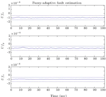
- Scenario 1: In the rst scenario, fault does not occur in the reaction wheels. In this scenario, the fault estimation has been presented in Figure 1, and the estimation error of satellite angular velocities has been depicted in Figure 2. These gures reveal that estimation error of the angular velocities is negli-gible, and the fault estimation in reaction wheels is less than the selected threshold, which has been shown by dash lines. So, as expected, no fault has been declared. As can be observed in Figure 1, the fault estimation is not exactly zero, which may be attributed to the disturbances and noise eects. Also, it is evident that the threshold value has been appropriately and nely selected to avoid false fault declaration.
- Scenario 2: In the second scenario, an abrupt fault has been occurred in the reaction wheel, aligned
Figure 1. Fault estimation of actuators in the rst scenario.
Figure 2. Estimation error of the satellite angular velocities in the rst scenario.
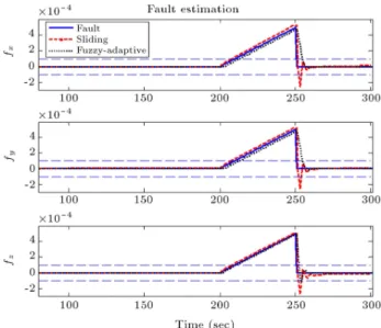
with the x axis, at a time between 200 sec and 250 sec, and with the magnitude 10 3N.m. In these
conditions, Figure 3 presents the fault estimation in reaction wheels, and Figure 4 shows the estimation error of angular velocities. The results depicted in Figure 3 imply that only the fault estimation value, aligned with the x axis, has been exceeded the selected threshold, and so, fault is only declared in this axis. Therefore, the designed algorithm has provided the nice feature of isolating the faulty component. Moreover, the fault estimation value, compared to the real value, illustrates that the adaptive observer has the capability to nely and accurately estimate the fault terms. This feature
Figure 3. Fault estimation of actuators in the second scenario.
Figure 4. Estimation error of the satellite angular velocities in the second scenario.
leads to the boundedness of the estimation error of angular velocities, despite the fault occurrence in the reaction wheels. This error deviates only in the fault occurrence times which damps immediately. Note that in Figure 3, performance of the developed method has been compared with a fault estimator based on the Sliding Mode Observer (SMO) [21,23]. As shown in this gure, the fault estimated by the Fuzzy-Adaptive Observer (FAO) represents an overshoot of 1.7%, settling time of 13 sec and estimation error of 0.1%; however, the SMO method provides an overshoot of 55%, the settling time of 28 sec and the estimation error of 2%.
- Scenario 3: To further substantiate the FDD algo-rithm robustness, in this scenario, incipient faults
with the slope 10 5 N.m have been applied in
all three reaction wheels. The Above faults have occurred at 200 sec. In this regard, Figure 5 shows the fault estimation in reaction wheels, and the estimation error of angular velocities has been depicted in Figure 6. As can be seen in Figure 5, the fault estimation in all three axes violates the selected threshold at a considered time interval, which veries the performance of the fault detection algorithm. Also, it reveals that the fault magnitudes are accurately estimated. Figure 6 shows that the estimation error of angular velocities is bounded in spite of fault occurrence, which attributed to the fault estimation capability of the adaptive observer. Note that in Figure 5, performance of the
devel-Figure 5. Fault estimation of actuators in the third scenario.
Figure 6. Estimation error of the satellite angular velocities in the third scenario.
Table 1. Performance of the proposed method in comparison to the sliding mode observer approach. Fault detection
time Overshoot
Settling time
Fault estimation
accuracy
Sensitivity to sample
rate
Fault type SMO FAO SMO FAO SMO FAO SMO FAO SMO FAO
Abrupt 2.1 sec 2.5 sec 55% 1.7% 28 sec 13 sec 2% 0.1% High Normal
Incipient 10 sec 12 sec | | | | 4.6% 1.9% High Normal
oped method has been compared with the SMO. It can be seen that the estimation error of 1.9% is attained using the developed method; however, an estimation error of 4.6% is provided by the SMO method. Similarly, by carrying out simulations for dierent scenarios, eectiveness of the proposed fault detection, isolation and identication algorithms is demonstrated. The associated graphs are not shown here for brevity.
Table 1 summarizes the results obtained by the FAO in comparison to the SMO. According to this table, although the fault detection times, provided by the outlined methods, are almost close to each other (sliding mode estimator yields a somewhat better performance), the estimation accuracy achieved by the FAO is signicantly better than the SMO. Also, our investigations show that the SMO approach is more sensitive to the sampling time variations. Accordingly, the estimation ability attained, using the FAO, pro-vides a better match, compared to the real fault value. The outlined ability is especially important about the compensators which use the estimated fault term to maintain the system stability. In fact, a more accurate fault estimation can eventually lead to a more robust remedial action.
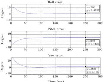
Next step is verication of the recovery algorithm. For this purpose, satellite attitude error is shown in Figure 7. As can be observed from this simulation, the value 0.0062 deg has been obtained as the pointing accuracy in presence of noise and disturbance torques. So, it reveals that an acceptable orientation response has been achieved by the backstepping feedback lin-earization control law, and the satellite has reached the desired angle. Now, performance of the recovery algorithm is investigated against abrupt faults with the magnitude 10 3 N.m, which are introduced in all
three reaction wheels at 120 sec. For this, Figure 8 depicts the satellite attitude errors about the roll, pitch and yaw axes, in which the compensator controller has not been utilized. Based on the obtained results, tracking errors 147 deg about the yaw axis, 0.44 deg about the pitch axis and 0.47 deg about the roll axis have been gained. So, the system performance is signicantly degraded after actuator faults, which may lead to undesired eects on mission imaging resolution.
Figure 7. Attitude errors about the roll, pitch and yaw axes in case of no fault occurrence at the satellite reaction wheels and without fault compensation.
Figure 8. Attitude errors about the roll, pitch and yaw axes in case of fault occurrence at the satellite reaction wheels and without fault compensation.
Moreover, occurrence of an abrupt fault with a larger magnitude or an intermittent fault may lead to a more severe eect or even loss of the satellite control.
Therefore, the necessity of utilizing a compensator controller, together with the designed algorithm is evident. With activation of the compensator controller,
Figure 9. Attitude errors about the t roll, pitch and yaw axes in case of fault occurrence at the satellite reaction wheels and together with fault compensation.
the satellite attitude errors have been illustrated again in Figure 9. It can be seen that high control precision and a good tracking process are still obtained, despite fault existence in actuators and deviation of their generated control torques from the desired values. So, the satellite maintains the desired attitude, and eectiveness and applicability of the recovery algorithm are veried. Summarizing all the cases, it is noted that the proposed adaptive observer provides fault
identication with an acceptable accuracy. Utilizing this capability combined with the threshold selection process leads to a high reliability attributed to the fault detection and identication processes.
Another important merit of the designed algo-rithm is that in case of fault occurrence in an actuator, only the fault term associated with that actuator violates the selected threshold, which typically provides the fault isolation capability. Simulation results also show that the recovery algorithm can signicantly improve the normal performance mode, and so this feature together with the outlined fault detection, isolation and identication capabilities achieves an au-tomatic and independent fault tolerant attitude control system.
7. Hardware In the Loop (HIL) test
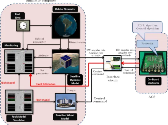
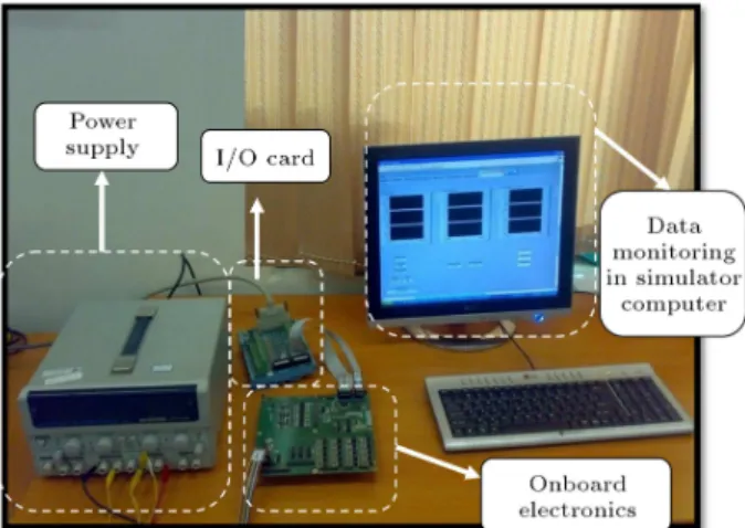
To evaluate the potentialities of utilizing the proposed algorithms in real applications, and investigate their capability to onboard implementation, in this section, the results of the Hardware In the Loop (HIL) tests are presented. These experimental results validate the desired requirements attributed to the designed algorithms considering the real conditions, which the satellite may experience in the orbital situations. For this, hardware in the loop test bed is planned according to Figure 10, which provides the ability to test Fault Detection, Isolation and Recovery (FDIR) algorithms
in close to a real-time condition. This facility includes the following main elements:
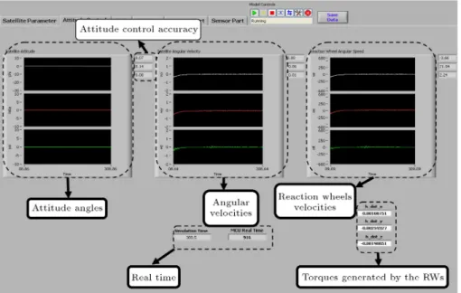
Simulator computer: this simulator which has been created by the lab view software provides the pos-sibility to accurately model the satellite dynam-ics, considering the factors such as uncertainties, space disturbances, sensor noise and reaction wheel models. In this environment, we also have the fault simulator to monitor the parameters related to the FDIR algorithms, and analyze their perfor-mance. The simulator computer also provides a special monitoring environment to track the control algorithms, their generated moments which apply to the satellite, and the angular rates which have been achieved by them.
On-board electronics: the fault detection, identica-tion and recovery algorithms have been implemented in this element. The processor utilized in this product is selected from the 8051 family which, in addition to satisfy our technical specications, has a history of use in dierent space missions. This element also provides the exibility to implement and evaluate dierent attitude control and FDIR algorithms. As seen from Figure 10, the onboard electronics receives the satellite attitude, satellite angular rates and reaction wheel angular rates as its input states, and after process and execution of the implemented FDIR algorithms, generates the torque commands and FDI output signals, which should be transmitted to the simulator computer. The torque command is generated by the recovery algorithm after fault declaration by the FDI algorithm, which should be applied to the satellite simulator model to guarantee its stability.
Interface circuits: Interface circuits consist of the appropriately selected I=O cards which have the role of receiving the output states of the computer simu-lator and transmitting the output signals generated by the FDIR algorithm.
Figure 11 shows a real view of the mentioned elements and their connections. connected to each other.
Figure 12 depicts the test results for a scenario in which abrupt faults have occurred in each of the three reaction wheels. As this gure reveals, in spite of the faults in the reaction wheels, estimation errors of the implemented adaptive observer remains bounded. Also, the fault estimations track the real fault proles, and so validate the fault detection and identication performances in an onboard implementation test. As seen in this gure, the fault estimations are corrupted by noise, due to the measuring sensors. To cope with this event and prevent false fault declaration, the fault estimation signals have been ltered by onboard electronics, as it was represented in Figure 12. This
Figure 11. Hardware in the loop test facility.
gure shows that the ltered signals provide smooth proles which are more compatible with the real fault proles, and hence it is possible to achieve a more accurate and ne FDD process.
To evaluate the FDD performance in a case in which the FDD algorithms are exposed to a high severity of sensor noises, Figure 13 presents the fault simulator outputs in a condition where the measured signals are corrupted by a noise with the standard deviation 10 3rad/sec. As the ltered signals depicted
in this gure reveal, even in these harsh conditions, the fault declaration process works correctly, and the fault estimation prole tracks the real fault prole applied to the reaction wheels.
Figures 14 and 15 represent the satellite attitude angles and angular velocities achieved by the recovery algorithm implemented in the onboard electronics. Figure 14 shows the variables of interest in conditions where no compensation has been accomplished. As can be observed, an oset has appeared in the yaw axis angle ( ). Figure 15 depicts the results when the compensation algorithm has been activated. It is evident from this gure that despite fault existence in the actuators, the satellite maintains its stability, and no oset has appeared in the satellite states.
Table 2 indicates a comparison between simula-tion and experimental results of the developed recovery algorithm. As this table illustrates, there are some deviations between the results depicted. According to our expectation, the obtained results in the simulation case is somewhat better than the experimental case which is reasonable due to reasons detailed below:
1. Accuracy of the oat calculations in the on-board electronics processor is more restrictive than the CPU of the simulator computer, so some deviations between the related results occur.
2. The major deviation between these two results originates from the analog to digital and digital to analog conversions.
Figure 12. Fault detection and identication test results after fault occurrence in the reaction wheels.
Figure 13. Fault detection and isolation test results after intermittent fault occurrence in the reaction wheel, aligned with the x axis, considering a measuring noise with the standard deviation of 10 3 rad/sec.
Table 2. Simulation and experimental results of the recovery algorithm. No fault
Fault application in all three reaction wheels with no recovery activation
Fault application in all three reaction wheels and utilizing the recovery algorithm Simulation
results
Experimental results
Simulation results
Experimental results
Simulation results
Experimental results
Roll error 0:0062 0:09 0:4778 0:48 0:0086 0:07
Pitch error 0:0017 0:15 0:4433 0:36 0:0023 0:14
Figure 14. Satellite attitude angles after fault occurrence in each of the three reaction wheels and without fault compensation.
Figure 15. Satellite attitude angles after fault occurrence in each of the three reaction wheels and with activation of the fault compensating algorithm.
Since the data must be transferred between the on-board electronics and the simulator computer, a 16 bit conversion is inevitable, so this conversion error may lead to deterioration of the experimental results. Note that since in real situations there is no need to transfer data between the on- board electronics and the computer, this error is not a problem. In fact, the requested attitude determination data received directly from the attitude sensors and the generated torque by the reaction wheels is directly applied on the satellite body. As a result, although there are some deviations between simulation results and experimental results,
due to the reasons stated, these deviations are not critical, and the results obtained are accurate enough for application in orbit.
8. Conclusions
This paper described both theoretical and experimental results focused on a study of fault tolerant attitude control system. The proposed FDD algorithms pro-vide the ability of actuators fault detection, accurate identication of their magnitudes and also the isolation possibility between them. The above capabilities
were achieved under the conditions where no prior information about the fault nature was used in the FDD design process. The FDD design was evaluated using several dierent types of reaction wheel failure scenarios, through which the desired performance were validated taking into account the disturbances, uncer-tainties and unknown faults.
In this paper, also the design steps of the re-covery algorithm, based on a backstepping feedback linearization controller, were presented, in which the fault magnitude estimation accomplished by the FDD algorithm was utilized. As the simulation results revealed, this algorithm provided the compensation ability of the fault eect such that no deviation of the system from the desired pointing attitude occurred. These analytical investigations demonstrated the ro-bustness of the control design to the disturbances, measurement noise and unknown faults, and so the expected performance was achieved. To highlight the potentialities of the proposed algorithms in real applications, hardware in the loop test facility was planned to study the digital implementation of the designed algorithms, and provide more accurate and realistic results. As observed from the test results, the developed algorithms maintained their desired performances, which validated their feasibility in real-time implementations. Future work is planned to study reliability and dependability analyses which are of paramount importance for aerospace applications.
References
1. Venkateswaran, N., Siva, M.S. and Goel, P.S. \Ana-lytical redundancy based fault detection of gyroscopes in spacecraft applications", Acta Astronautica, 50(9), pp. 535-545 (2002).
2. Castet, J.F. and Saleh, J.H. \Satellite and satellite subsystems reliability: Statistical data analysis and modeling, reliability engineering and system safety", Reliability Engineering & System Safety, 94, pp. 1718-1728 (2009).
3. Patton, R.J. \Fault detection and diagnosis in aerospace systems using analytical redundancy", Com-puting and Control Engineering Journal, pp. 127-136 (1991).
4. Hwang, I. and Kim, S. \A survey of fault detection, isolation and reconguration methods", IEEE Trans-actions on Control Systems Technology, 18(3), pp. 636-653 (2010).
5. Frank, P.M. \Fault diagnosis in dynamic systems using analytical and knowledge-based redundancy-a survey and some new results", Automatica, 26(3), pp. 459-474 (1990).
6. Iserman, R. \Model-based fault detection and diagnosis-status and applications", Annual Reviews in Control, 29, pp. 71-85 (2005).
7. Venkatasubramanian, V., Rengaswamy, R. and Kavuri, S.N. \A review of process fault detection and diagnosis. Part I: Quantitative model-based methods", Computers & Chemical Engineering, 27, pp. 293-311 (2003).
8. Valdes, A. and Khorasani, K. \A pulsed plasma thruster fault detection and isolation strategy for formation ying of satellites", Applied Soft Computing, 10, pp. 746-758 (2010).
9. Li, Z.Q., Ma, L. and Khorasani, K. \A dynamic neural network-based reaction wheel fault diagnosis for satellites", International Joint Conference on Neural Networks Sheraton Vancouver Wall Centre Hotel, Van-couver, BC, Canada, pp. 3714-3721 (2006).
10. Fan, C., Jin, Z., Zhang, J. and Tian, W. \Application of multi sensor data fusion based on RBF neural networks for fault diagnosis of SAMs", Seventh Inter-national Conference on Control, Robotics and Vision, 3, pp. 1557-1562 (2002).
11. Zhao, S. and Khorasani, K. \A recurrent neural network based fault diagnosis scheme for a satellite", The 33rd Annual Conference of the IEEE Industrial Electronics Society, Nov. 5-8, Taipei, Taiwan, pp. 2660-2665 (2007).
12. Pirmoradi, F.N., Sassani, F. and Silva, C.W.D. \Fault detection and diagnosis in a spacecraft attitude deter-mination system", Acta Astronautica, 65, pp. 710-729 (2009).
13. Okatan, A., Hajyev, C. and Hajiyeva, U. \Kalman lter innovation sequence based fault detection in Leo satellite attitude determination and control system", 3rd International Conference on Recent Advances in Space Technologies RAST `07, Istanbul, pp. 411-416 (2007).
14. Xiong, K., Chan, C.W. and Zhang, H.Y. \Detection of satellites attitude sensor faults using the UKF", IEEE Transactions on Aerospace and Electronics Systems, 43(2), pp. 480-491 (2007).
15. Soken, H.E. and Hajiyev, C. \Pico satellite attitude estimation via robust unscented Kalman lter in the presence of measurement faults", ISA Transactions, 49, pp. 249-256 (2010).
16. Bae, J. and Kim, Y. \Attitude estimation for satel-lite fault tolerant system using federated unscented Kalman lter", International Journal of Aeronautical & Space Science, 11(2), pp. 80-86 (2010).
17. Tudorou, N. and Khorasani, K. \Satellite fault diagno-sis using a bank of interacting Kalman lters", IEEE Transactions on Aerospace and Electronics Systems, 43(4), pp. 1334-1350 (2007).
18. Patton, R.J., Uppal, F.J., Simani, S. and Polle, B. \Robust FDI applied to thruster faults of a satellite system", Control Engineering Practice, 18, pp. 1093-1109 (2010).
19. Patton, R.J., Uppal, F.J., Simani, S. and Polle, B. \Reliable fault diagnosis scheme for a spacecraft attitude control system", Proc. IMechE, Part O: J. Risk and Reliability, 222, pp. 139-152 (2008).
20. Henry, D. \Robust fault diagnosis of the microscope satellite micro-thrusters", IFAC Fault Detection, Su-pervision and Safety of Technical Processes, Beijing, pp. 342-347 (2006).
21. Jiang, T. and Khorasani, K. \A fault detection, isolation and reconstruction strategy for a satellite's attitude control subsystem with redundant reaction wheels", IEEE International Conference on Systems, Man and Cybernetics, Montreal, Que, pp. 3146-3152 (2007).
22. Wu, L., Zhang, Y. and Li, H. \Research on fault detection for satellite attitude control systems based on sliding mode observers", IEEE International Con-ference on Mechatronics and Automation, Changchun, China, pp. 4408-4413 (2009).
23. Wu, Q. and Saif, M. \Robust fault diagnosis of a satellite system using a learning strategy and second order sliding mode observer", IEEE Systems Journal, 4(1), pp. 112-121 (2010).
24. Zhang, K., Jiang, B. and Shi, P. \Adaptive observer-based fault diagnosis with application to satellite attitude control systems", Second International Con-ference on Innovative Computing, Information and Control, Kumamoto, pp. 508-508 (2007).
25. Wang, J. Jiang, B. and Shi, P. \Adaptive observer based fault diagnosis for satellite attitude control sys-tems", International Journal of Innovative Computing, Information and Control, ICIC International, 4(8), pp. 1921-1929 (2008).
26. Tanaka, K. and Wang, H.O., Fuzzy Control System Design and Analysis, John Wiley & Sons, pp. 5-10 (2001).
27. Sidi, M.J., Spacecraft Dynamics and Control, Cam-bridge University Press, pp. 88-95 (1997).
28. Jiang, B., Gao, Z., Shi, P. and Xu, Y. \Adaptive fault-tolerant tracking control of near-space vehicle using Takagi-Sugeno fuzzy models", IEEE Trans. Fuzzy Sys-tems, 18(5), pp. 1000-1007 (2010).
29. Ichalal, D., Marx, B., Ragot, J. and Maquin, D. \Fault tolerant control for Takagi-Sugeno systems with unmeasurable premise variables by trajectory track-ing", IEEE International Symposium on Industrial Electronics, pp. 2097-2102 (2010)
30. Khalil, H., Nonlinear Systems, 2nd Ed. Upper Saddle River, NJ, Prentice-Hall, pp. 588-601 (1996).
31. Chen, C.T., Linear System Theory and Design, Holt, Rinehart and Winston, pp. 400-404 (1970).
Biographies
Hossein Bolandi received his DSc degree in Electri-cal Engineering from George Washington University, Washington, D.C., in 1990. Since 1990 he has been with the College of Electrical Engineering, Iran Uni-versity of Science and Technology, Tehran, Iran, where he is an associate professor. His research interests are in attitude determination and control subsystems of satellites, adaptive control, automation and guidance, and navigation and control.
Mehran Haghparast received his BSc and MSc degrees in Electrical Engineering from Iran University of Science and Technology, Tehran, Iran in 2008 and 2011, respectively. His research interests are in attitude control subsystems of satellites, fault detection and isolation system, robust control and applied control theory.
Mostafa Abedi received his BSc degree in Electrical Engineering from the Chamran University and his MSc degree from the Iran University of Science and Technology in 2004 and 2007, respectively. He is now PhD candidate in the electrical department, Iran Uni-versity of Science and Technology, Tehran. His research interests are in attitude determination of satellites, satellite sensors, fault detection and isolation.