http://www.jscdss.com
Vol.2 No.4 August 2015: 31-41 Article history:
Accepted 23 July 2015 Published online 23 July 2015
Journal of Soft Computing and Decision
Support Systems
PID Controller Optimization for Rotational Inverted Pendulum System
Using Particle Swarm Optimization and Differential Evolution
Algorithms
Elham Yazdani Bejarbaneh a,*
a
Faculty of Electrical Engineering, Universiti Technologi Malaysia, Johor, Malaysia
* Corresponding author email address: [email protected]
Abstract
This paper presents stochastic search techniques, including Particle Swarm Optimization (PSO), Constriction Coefficient Particle Swarm Optimization (CPSO) and Differential Evolution (DE) algorithms for determining optimal Proportional-Integral-Derivative (PID) controller parameters attached to the Rotational Inverted Pendulum (RIP) system. This paper demonstrates in detail how to employ these proposed algorithms to optimize the performance index for balancing the pendulum in vertical-upright position. The efficiency of these intelligent strategies to tune PID gains is compared and evaluated based on the time response performance. The simulation results clearly demonstrate superior features of proposed tuning approaches, including easy implementation, and good computational efficiency. The overall results have validated that CPSO method yields better performance in control action compared to PSO and DE. The proposed approaches could generally be considered as an encouraging way for control of nonlinear industrial plants.
Keywords: Particle Swarm Optimization, Constriction Coefficient, Differential Evolution, Proportional-Integral-Derivative controller, Rotational Inverted Pendulum
1. Introduction
Rotary Inverted Pendulum (RIP) system as a well-known test platform system has always been one of the fundamental and controversial problems in control theory due to its inherent nonlinear and unstable dynamic behavior (Yan, 2003; Muskinja et al., 2006; Oltean, 2014). RIP has been also applied as a familiar system for various real life applications until today such as aerospace automobile control, robotics, control professionals, pendulum rides, rockets, robotic arm, the flight simulation of rocket or missile, and other transportation means (Jones, 1992; Drof et al., 1995; Lei et al., 1997; Van den berg, 2003; Muskinja et al., 2006).
During, the past years, numerous classical, as well as, modern control approaches such as Proportional Integral Derivative (PID) (Gaing, 2004), nonlinear control (Yan, 2003), Linear Quadratic Regulator (LQR) (Zhong et al., 2001), adaptive, and optimal (Sukontanakarn et al., 2006; Cong et al., 2009; Phuong et al., 2013) controllers have been introduced and applied on the balancing of RIP system. However, these control methodologies are theoretically challenging and complex to deal with the nonlinearities of RIP system. Therefore, designing a compatible and solvable controller which satisfies all of the
design requirements of RIP system has become a vital issue.
Proportional-Integral-Derivative (PID) controller on the
other hand, has been employed in various operating
conditions of industrial plants and still in demand due to its simplicity in structure and robustness in performance (Visioli, 2001; Eibayomy et al., 2008). Nevertheless, the precisely tuning of the gains has become the drawback of this controller due to the higher order systems or plants, disturbances, and nonlinearities (Kwok et al., 1993; Gaing, 2004).
At the earlier times, Ziegler and Nichols (Ziegler et al., 1943) method has been broadly applied as classical tuning rule to adjust the PID controller parameters. However, the determination of optimal PID parameters by utilizing Ziegler-Nichols method still results in less optimal performance for a wide range of nonlinear plants (Visioli, 2001; Gaing, 2004).
To overcome these difficulties, the evolutionary
algorithmshave recently received great attention to provide
a tuning capability of PID gains such as Simulated Annealing (SA) as a high efficient optimization method (Zhou et al., 1994) and Genetic Algorithm (GA) as a parallel search technique to tune PID parameters (Haupt et
al., 1998; Rani et al., 2011; Hassanzadeh and Mobayen,
2011; Amanullah et al., 2014). Though, the SA method
requires a large number of computations to find optimal solution (Subramanian et al., 2005), as well as, the natural process of GA would still result in slow convergence tendency (Haupt et al., 2004).
GA deficiencies such as similarity in structure of
chromosomes (Kennedy et al., 1995; Gaing, 2004) is improved, using a novel global search strategy, called Particle Swarm Optimization (PSO) algorithm. PSO is a new meta-heuristic algorithm which is inspired by structure of a social system (Kennedy et al., 1995). It is widely applied within the control community due to its simple theory, easy implementation and less computational time which can lead to generate high-quality solutions with reasonable speed (Zadeh et al., 2008).
Moreover, the Differential Evolution (DE) algorithm has been successfully applied to various optimization fields because of its fast convergence and easy understanding (Nayak, 2011) in finding high efficient solutions . In this paper, the efficiency of different intelligent strategies are compared and evaluated for searching optimal PID controller as an optimization dilemma to make sure sufficient controlling behaviour of the closed-loop system of RIP.
Hence, in this study, we apply Lagrange concept in order to obtain mathematical model of RIP system. Moreover, we compare the efficiency of three intelligent algorithms including PSO, CPSO, DE methods which are used to determine optimal PID controller parameters.
2. Modelling Rotary Inverted Pendulum system
The rotational structure of the RIP system, as shown in Fig. 1, consists of a pendulum and a rotary arm rotating in vertical and horizontal plane, respectively where rotary arm mounted on the shaft of the servo motor is actuated by the servo motor, while the pendulum hangs downwards. The RIP system is inherently unstable, and should be dynamically remained in a steady state upright position, either by applying a torque at the actuating arm or by moving the actuating arm horizontally as part of a feedback system.
Fig. 1. The structure of a rotary inverted pendulum.
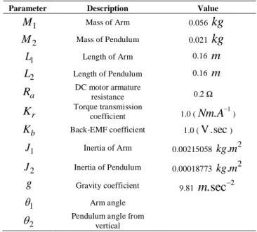
For this case, the physical parameters of RIP model PP-300 is assumed, shown in Table 1.
Table 1
Physical parameters of rotary inverted pendulum.
Parameter Description Value
1
M Mass of Arm 0.056
kg
2
M Mass of Pendulum 0.021
kg
1
L Length of Arm 0.16 m
2
L Length of Pendulum 0.16 m
a
R DC motor armature resistance 0.2Ω
r
K Torque transmission coefficient 1.0 (Nm A. 1)
b
K Back-EMF coefficient 1.0 (V.sec)
1
J Inertia of Arm 0.00215058 kg m. 2
2
J Inertia of Pendulum 0.00018773 kg m. 2
g
Gravity coefficient 9.81m
.sec
21
Arm angle
2
Pendulum angle from
vertical
The dynamic equations of the RIP are developed on the Lagrange analysis. The Lagrange equation of motion is described as,
1, ..., n
i i i
d l l
i Q dt
(1)
where,
Q
idenotes the external force.In the Lagrange equation, the Lagrange function, L is defined based on the kinetic and potential energy of the system as follows:
L
T U
(2) where, T and U denote the kinetic and potential energy of the system, respectively.In the first step, the kinetic and potential energy of the
system should be described in terms of two coordinates (
1and
2).The velocities of two links can be derived from their position. The position of each of two links in terms of x, y, and z components is expressed as,
1 1 1 2 1 1 2 1 2
1 1 2 1 1 2 1 2
1 2 2 2
cos cos sin sin
sin , sin cos sin
1
0 cos
x l x l l
y l y l l
z z l
(3)
The total kinetic energy of the system is the sum of
kinetic energy of the rotary arm
m
1, and the pendulumm
2 ,are differentiated with respect to time.
2 2 2 2
1 1 1 1 1 1
2 2 2 2
2 2 2 2 2 2
1 / 2 1 / 2 )
1 / 2 1 / 2 (
(
)
T J m x y z
J m x y z
Then, the kinetic energy of two links based on their velocities is developed to gain the total kinetic energy of the system.
2 2 2 2
1 1 1 1 1 2 2 2 2 2 2 2 2
2 1 2 2 1 2 2 1 2 1 2 2
1 / 2 1 / 2 1 / 2
1 / 2 (( ) 2 )
T J m l J
m l l sin l l l c so
(5)
The potential energy of the system is stored in the pendulum in the form of gravitation. The potential energy of the system, U can be defined as,
2 2 2
U m gl cos (6) Therefore, the Lagrange equation of system is yielded by substituting Eqs. (5) and (6) into Eq. (2).
2 2 2 2 2 2
1 1 2 2 1 2 1 1 22 2 1
1 / 2 1 / 2 1 / 2( ) 1 / 2
L J J m m l m l sin
2 2
2 2 2 2 1 2 1 2 2 2 2 2
1 / 2m l m l l cos m gl cos
(7)
The derivatives of Lagrange function can then be represented in Eqs. 8 and 9 by substituting the derivatives of
1( )
t
and
2( )
t
from Eq. (7).1 1
d l l
dt
(8)2 2
0
d l l
dt
(9)Where, the relation between the control torque (τ) and
the control voltage (e) is given by Eq. (10) (Uo-Huang,
2006), 2 1 b b m m K K e R R
(10)
The nonlinear equations of motion without considering friction effects can be represented in Eqs. (11) and (12) (Bejarbaneh, 2012).
2 2 2
1 1
(
1 2)
1 1 2 1 2 2 2 2 2 2 1J
m
m l
m l l
cos
m l sin
2 2
2 2 2 1 2 2 2 1 2 2 2
2
l m
cos sin
m l l
sin
(11)2
2 2 2 2 2 2 1 2 1 2 2
2 2 2 2 2 1 2 2
0
J
m l
m l l
cos
m gl sin
m l
sin cos
(12)Eqs. (11) and (12) can be presented in the matric form as below,
2 2
2 2 2 2 2 2 2 1 2 2 212 2 2 1
2
22 1 2 2 2
1
2 2 2
1 1 2 1 2 2 2 2 1 2 2 2
2
2 1 2 2 2 2 2
cos sin cos sin sin
sin cos 0
sin cos
cos
l m l m m l
m l
l
J m m l m l m l l
m l l J m l
2 2 2
0
0
m gl sin
(13)The linear model of RIP around configuration point (
2
) is given by Eq. (14).* ( )
+ *
̈
̈ + + [ ]
=* ( ) ̇+ (14)
̈=[ ( )( ) ] ̇ [ ] *( )( )+ (15) ̈=* ( )+ [ ( )( )] ̇ +* ( )+
e (16)
where,
= ( + ) + ( ) +
The linear model of a RIP system consists of mathematical equations as determined by Eqs. (15) and (16) is shown in Fig. 2.
With regard to the numerical value of RIP parameters in Table1, the state space form of linearized RIP model is given by Eq. (17).
[ ̇ ̇ ̈ ̈ ] [ ̇ ̇ ] [
] (17)
3. Controller design
3.2 PID controller design
For this research, the controller design will focus on the simple PID controller algorithm. The main reason to choose the PID controller is because it much easier to design compared to other controllers. With this under-actuated system, it is necessary to apply two PID controllers: one for controlling
1 (PID 1) and the otherone for controlling
2 (PID 2). The initial angular positionof arm,
1, and the pendulum,
2, is assumed zero andability tuned by evolutionary algorithms. The nonlinear equations for modeling RIP system are given by Eqs. (11) and (12).
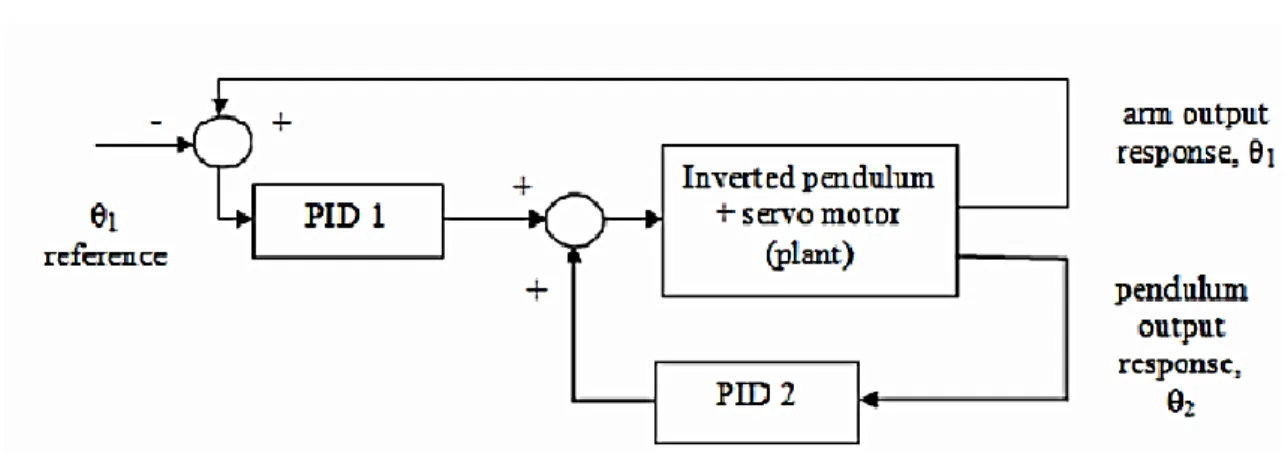
The strategy of the rotary inverted pendulum control system is represented in Fig. 3.
Fig. 2. Simulink model of linear RIP system.
Fig. 3. The structure of the rotary inverted pendulum control system.
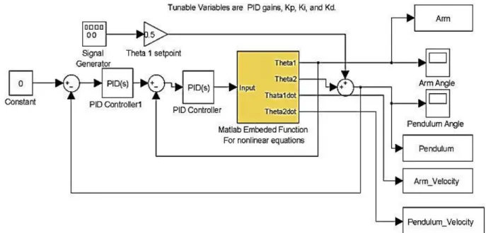
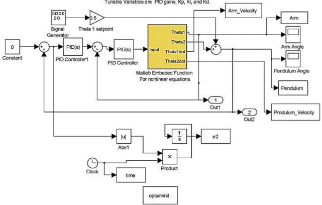
The Simulink block diagram of the RIP on MATLAB platform is shown in Fig. 4, where the angular
displacement of arm
1, is configured by the input voltageV, the main objective is to stabilize the pendulum angle,
2
as zero so that the inverted pendulum maintains itsFig. 4. Simulink block diagram of the proposed PID strategy.
4. Particle Swarm Optimization
4.2 Overview of original PSO
Particle swarm optimization algorithm was introduced first time by Eberhart and Kennedy in 1995 (Kennedy et al., 1995). It is a new meta-heuristic search method that uses the social behaviour of swarm of birds as a source of inspiration. In this paper, this algorithm serves PID controller on RIP plant associated with nonlinearities. First of all, PSO algorithm creates a population of random particles.
These particles have two critical abilities: their memory of their own best position (
P
best) and their awareness ofthe swarm best position (
G
best). Next, Particles of a swarmshare good positions between each other and update their own position and velocity according to Eqs. (19) and (20). In this problem, search space is three-dimensional axes that
areKp,
K
i, andK
d axes. The algorithm procedure canbe expressed in following flowchart.
X
(
,
,
)
(
,
,
)
(V , V , V )
i iP iI iD p i d
i iP iI iD
X
X
X
K
K K
V
(18)
1 1i, j i, j i, j
2 2 i, j
v k 1
w.v k
c r gbe
(
)
(
)
st
x k
c r pbest
jx k
(19)
i, j
i, j
i, jx k 1
x k
v k
(20)Where, V
k i,jandx
k i, jare the velocity andposition of particle i and dimension j, respectively,
whereas, C C1
,
2are the acceleration factors,r r
1,
2arerandom numbers, w is the inertia weight factor,
p
bestandbest
g
are the best position of a particle and swarm,respectively.
For all algorithms, in every problem, a fitness function must be defined. In this problem, the aim is to minimize every performance index of F function, including of
Integral Time Absolute Error and the overshoot criteria.
This cost function is applied to evaluate its ability to tune PID controller attached to RIP system.
α*ITAE+β*Overshoot
F
(21)Where, ITAE is the Integral Time Absolute Error criteria, α and β are improvement factors, respectively.
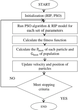
Fig. 5. The flowchart of PSO-PID controller design.
4.3 Constriction Coefficient. PSO
In order to more exploration of complex search area in 2002, constriction coefficient approach was proposed by Clerc and Kennedy (Clerc et al., 2002) which is used in this paper.Thismethodisintroducedaspecificparameter‘χ’as constriction factor. The velocity update formula of adaptive model excluded the inertia weight ω and the maximum
velocity ( ) parameter. The velocity update formula can
be expressed as follow,
1 1
2 2
1
[
. .
. .
]
id id id id
id id
V
t
V
t
C
P
t
X
t
C
g
t
X
t
(22)(
1)
( )
(
1)
id
t
id idX
X
t
V t
(23)where,
1 2
2
2
4
4
with
C
C
(24)In order to initialize the parameters of PSO algorithm, constriction coefficient approach is proposed a specific
range for Inertia weight factor
( )
w
and acceleration factors1 2
(C C
,
)
of PSO algorithm as,1
,
20
where 1 2 4 (25)2
2
4
4
(26)Where,
denotes constriction coefficient factor.w
,C
1
.
an
d C
2
.
2 (27) The constriction coefficient method balances the requirement of searching for local and global search which leads to the fast convergence of the particles through all period of time. As during the search, the local search is applied when the local best position and the global best position are close to each other, whereas when the local best position and the global best position are far away from each other the global search is performed (Das et al., 2008).5. Deferential Evolution Algorithm
Differential evolution algorithm was introduced first time by Price and Storn in 1997 (Storn et al., 1997). It is a population based algorithm.
START
Initialization (RIP, PSO)
Run PSO algorithm & RIP model for
each set of parameters
Calculate the fitness function
Calculate the Pbest of each particle and
Gbest of population
Update velocity and position of particles
Meet stopping criteria
END
The DE algorithm is a population based algorithm like genetic algorithm which applies the three operators; crossover, mutation and selection. The main dissimilarity
DE with GA is in finding better solutions as genetic
algorithm depends on crossover whereas DE relies
on mutation operation. Also, DE utilizes a modern
crossover operator that can obtain more information to search for a better solution in comparison with GA. In this paper, DE algorithm serves PID controller on nonlinear RIP plant as a task involving of three parameters represented by a 3-dimensional vector. This algorithm starts with a population of random solution vectors and then this population is continually updated by applying three operators, including mutation, crossover and selection
operators as this procedure is shown in Fig. 6.
In mutation section three independent parameter vectors (r r1, 2, and r3 vectors) are selected randomly from the population. Next, a scalar factor (F) measures the difference of two vectors and the scaled difference are
added to the third one where trial vector V ti( )is generated
as follows,
,
1
1,.
2, 3,i j r j r j r j
V
t
X
t
F X
t
X
t
(28) In the crossover section the target vector is combined with the trial vector.
, 1 , 1
,
ji G ji G
ji G
V
if
randj
CR or j
rni
u
q
if
randj
CR and j
rni
(29)Finally, in selection section the new generated solution by the mutation and crossover operations is evaluated to choose the better one (Nayak, 2011).
, 1 , 1 ,
, , 1
(
)
otherwise
(
)
i G i G i
i G
G
i G
if
f X
u
u
X
x
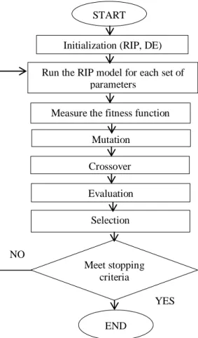
(30)6. RIP control system design by using intelligent techniques
The Simulink model of RIP control system by
using stochastic search methods and tuning parameters of
PSO and DE are presented in Fig. 7 and Table 2, respectively.
Fig. 6. The flowchart of DE-PID controller design.
START
Initialization (RIP, DE)
Run the RIP model for each set of parameters
Measure the fitness function
Mutation
Crossover
Evaluation
Selection
Meet stopping criteria criteria
END
Fig. 7. Simulink design of PID controller adjustment by using stochastic algorithms.
Table 2
Tuning parameters.
Parameter Value
Lower bound [K K Kp i d] [0 0 0]
Upper bound [K K Kp i d] [50 50 50]
Stopping criteria (iteration) 50 and 100
Population size 50
Crossover probability 0.2
Scaling factor Between 0.2 and 0.8
7. Simulation results
7.2 Convergence curve
The Simulation tool is applied to investigate the dynamic behavior and compare PID controller’s convergence characteristics. The number of function evaluation during the computation processes is considered. This value displays the accuracy of algorithms. As the convergence tendency of pendulum response by utilizing
PSO, CPSO and DE methods is depicted in Figs. 8, 9, and
10 respectively.
Fig. 8. Convergence tendency of PSO-PID controller.
0 5 10 15 20 25 30 35 40 45 50 0
1000 2000 3000 4000 5000 6000 7000 8000 9000
Number of Function Evaluation (NFE)
B
e
st
C
o
Fig. 9. Convergence tendency of CPSO-PID controller.
Fig. 10. Convergence tendency of DE-PID controller.
7.3 Performance based on servo behaviour
The performance of tuning techniques of
PID parameters is evaluated with regard to minimum
overshoot, less rise time and etc. Also, the reference
signal tracking behavior is evaluated on the RIP system.
For analysis of this performance, the typical positions
output response of PSO-PID, CPSO-PID, and DE-PID
controllers are indicated in Figs. 11, 12, and 13,
respectively.
Fig. 11. The pendulum response using PSO-PID controller.
Fig. 12. The pendulum response using CPSO-PID controller.
Fig. 13. The pendulum response using DE-PID controller.
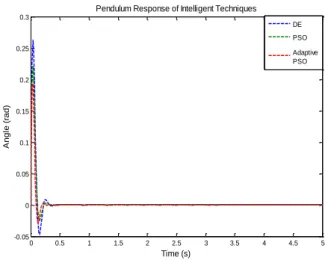
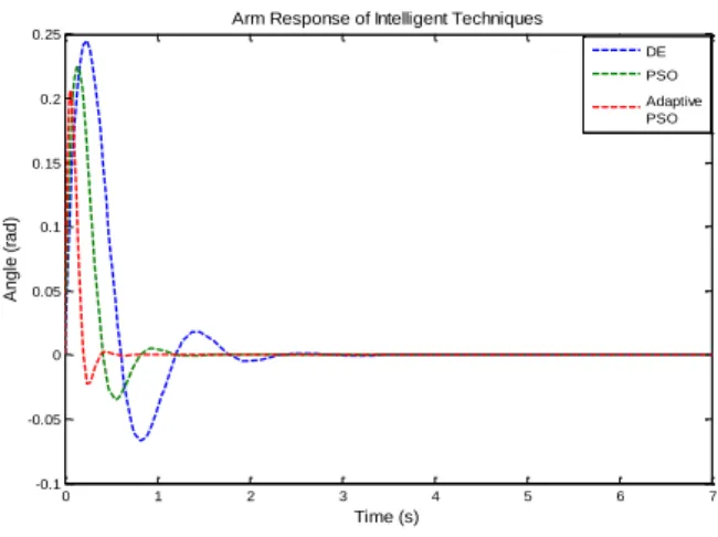
7.4 Comparison between different methods based on servo behaviour
A comparison of time-response performance by using intelligent techniques to control the pendulum angle and arm position is shown in Figs. 14 and 5 respectively.
Fig. 14. Comparative results of intelligent techniques.
0 5 10 15 20 25 30 35 40 45 50
0 1000 2000 3000 4000 5000 6000 7000 8000 9000 10000
Number of Function Evaluation (NFE)
B
e
st
C
o
st
0 10 20 30 40 50 60 70 80 90 100
0 1000 2000 3000 4000 5000 6000 7000 8000 9000 10000
Number of Function Evaluation (NFE)
B
e
st
C
o
st
0 0.5 1 1.5 2 2.5 3 3.5 4 4.5 5 -0.05
0 0.05 0.1 0.15 0.2 0.25 0.3
Time (s)
A
n
g
le
(
ra
d
)
Pendulum Response using PSO-PID Controller
0 0.5 1 1.5 2 2.5 3 3.5 4 4.5 5
-0.05 0 0.05 0.1 0.15 0.2
Time (s)
A
n
g
le
(
ra
d
)
Pendulum Response using Adaptive PSO-PID Controller
0 0.5 1 1.5 2 2.5 3 3.5 4 4.5 5
-0.05 0 0.05 0.1 0.15 0.2 0.25 0.3
Time (s)
A
n
g
le
(
ra
d
)
Pendulum Response using DE-PID Controller
0 0.5 1 1.5 2 2.5 3 3.5 4 4.5 5
-0.05 0 0.05 0.1 0.15 0.2 0.25 0.3
Time (s)
A
n
g
le
(
ra
d
)
Pendulum Response of Intelligent Techniques
Fig. 15. Comparative results of intelligent techniques.
The simulation result of the best solution to stabilize the pendulum angle in terms of number of iteration are summarized in Table 3, the time response performance of system is improved utilizing CPSO in comparison with DE and PSO techniques.
Furthermore, the convergence tendency of CPSO and PSO algorithms are faster than DE algorithm because of less number of iteration to obtain the minimum value of cost function. In addition, with regarding to overall cost values, CPSO has less cost value compared to PSO and DE techniques, showing that this method achieves better accuracy and smooth time response in control action. Though, all of algorithms establish efficient convergence of best cost value using the same cost function and simulation conditions.
Table 3
Best values of PID performance by using DE, PSO, and C PSO .
Parameter DE PSO CPSO
p
K
48.01 43.8 42.41i
K
0.0038 0.0011 0.011d
K
12.34 12.10 13.33r
T
(s)
0.0025 0.0019 0.0017
s
T
(s)
0.2886 0.2112 0.1938
ss
E
0.00 0.00 0.00Peak Time (s) 0.2631 0.2214 0.1938
Cost 19.17 17.13 9.48
Iteration 100 50 50
8. Conclusion
In this paper, three optimization approaches
proposed including, PSO, constriction coefficient. PSO and DE algorithms for tuning of PID controller attached to the nonlinear model of Rotary Inverted Pendulum system. Each of the algorithms was evaluated in different number of iteration as PSO and CPSO methods with 50 runs and DE method with 100 runs and these techniques gave different values at each program run due to the structure of algorithms based on the generation of random values. From the test problem analysis, the CPSO method is observed to have the best quality of solution compared to other
two techniques. Whereas, with regard to the
PID performance, DE algorithm requires more generation to fast convergence in comparison with other algorithms.
Hence, CPSO can be considered more efficient approach in terms of better accuracy, less iteration and computational
time compared to the traditional PSO
and DE algorithms. Through the simulation results, it is obvious thatthese proposed intelligent techniques establish a new prospective to find efficient optimal solution of PID gains for any nonlinear industrial plants with unknown process parameters. The implementation of hybrid stochastic algorithms such as PSO-DE and GA-PSO for designing adaptive controllers will be another challenging task in the future.
Acknowledgments
The authors would like to thank Universiti Teknologi Malaysia and the Ministry of Higher Education, Malaysia for their supports.
References
Akhtaruzzaman, M., Shafie, A.A. (2010). Modeling and control of a rotary inverted pendulum using various methods, comparative assessment and result analysis. Proceedings of IEEE International Conference on Mechatronics and Automation, 2010 (pp. 1342-1347).
Amanullah, M.D., Tiwari, P. (2014). Optimization of PID parameters in control system tuning with multi-objective genetic algorithm. International Journal of Engineering Research and Applications, 4(5), pp. 60-66.
Bejarbaneh, E.Y. (2012). Multi-optimization of PID controller parameters using stochastic search techniques for rotary inverted pendulum system. Master. Thesis, Universiti Teknologi Malaysia.
Clerc, M. and Kennedy, J. (2002). The particle swarm - explosion, stability, and convergence in a multidimensional complex space. IEEE Transactions on Evolutionary Computation, 6, pp. 58-73. Cong, S., and Liang, Y., (2009). PID-like neural network nonlinear
adaptive control for uncertain multivariable motion control systems. IEEE Transactions on Industrial Electronics, 56, pp. 3872-3879. Das, S., Abraham, A., and Konar, A. (2008). Particle Swarm Optimization
and Differential Evolution Algorithms: Technical Analysis,
Applications and Hybridization Perspectives. Advances of
Computational Intelligence in Industrial Systems, 116, pp. 1-38. Drof, R.C., and Bishop, R.H. B. (1995). Modern control systems. Reading,
MA: Pearson (Addison Wesley).
Eibayomy, K.M., Jiao, Z. and Zhang, H. (2008). PID controller optimization by GA and its performance on the electro-hydraulic servo control system. Chinese Journal of Aeronautics, 21, pp. 378-384.
0 1 2 3 4 5 6 7
-0.1 -0.05 0 0.05 0.1 0.15 0.2 0.25
Time (s)
A
n
g
le
(
ra
d
)
Arm Response of Intelligent Techniques
DE
PSO
Gaing, Z.L. (2004). A particle swarm optimization approach for optimum design of PID controller in AVR system. IEEE Transactions on Energy Compensation, 19, pp. 384-391.
Hassanzadeh, I., Mobayen, S. (2011). Controller design for rotary inverted pendulum system using evolutionary algoritms. Hindawi Publishing Corporation Mathematical Problems in Enginnering. 8, pp.1-11.
Haupt,R.L., S.EHaupt, S.E. (1998). PracticalGenetic Algorithms.New York, JohnWileyandSonsInc.
Jones, B.P.A.H. (1992). Genetic tuning of digital PID control. Electronics Letters, 28, pp. 834-844.
Kennedy, J., and Eberhart, R.C. (1995). Particle swarm optimization. Proceedings of the International Conference on Neural Networks, Australia, 1995 (pp. 1942-1948).
Kwok, D.P., Leung, T.P,, and Sheng, F. (1993). Genetic algorithms for optimal dynamic control of robot arms. Proceedings of the International Conference on Industrial Electronics, Control and Instrumentation, San Francisco, Nov 1993 (pp.380-385)
Lei, C.W.J.F., and Kin, L.K. (1997). Fuzzy Logic Controller for an Inverted Pendulum System. Proceedings of IEEE International Conference on Intelligent Processing systems, 1, 1997 (pp. 185- 189). Muskinja, N., Tovornik, B. (2006). Swinging up and stabilization of a real inverted pendulum. IEEE Transactions on Industrial Electronics, 53, pp. 631-639.
Nayak, M.R. (2011). Modified differential evolution optimization algorithm for multi-constraint optimal power. Proceedings of IEEE International Conference on Energy, Automation, and signal, 2011 (pp. 1-7).
Oltean, S.E. (2014). Swing-up and stabilization of the rotational inverted pendulum using PD and fuzzy-PD controllers. Proceedings of the International Conference of Interdisciplinary in Engineering, Romania, 2014 (pp. 57-64).
Phuong, N.T., Loc, H.D., Thuan, T.Q. (2013). Control of two wheeled inverted pendulum using sliding mode technique. International Journal of Engineering Research and Applications, 3, pp. 1267-1282. Rani, M.R., Selamat, H., Zamzuri, H., Ahmad, F. (2011). PID controller optimization for a rotational inverted pendulum using genetic algorithm. Proceedings of IEEE International Conference on Modeling, Simulation and Applied Optimization, 2010 (pp. 1-6). Rani, M.R., Selamat, H., Zamzuri, H., Zuwairie, I.(2012). Multi-objective
optimization for PID controller tuning using the global ranking genetic algorithm. International Journal of Innovative Computing, Information and Control, 8, pp. 269-284.
Stron, R., and Price, K. (1997). Differential Evolution, a simple and efficient heuristic strategy for global optimization over continuous spaces. Journal of global optimization, 11, pp. 341-359.
Subramanian, S., Bhuvaneswari, R. (2005). Optimization of Three-phase Induction Motor Design Using Simulated Annealing Algorithm. Electronic Power Components and Systems, 33, pp. 947-956. Sukontanakarn, V., and Parnichkun, M., (2006). Real-Time optimal
control for rotary inverted pendulum. American Journal of Applied Science, 6(6), pp. 1106-1115.
Uo-Huang, L. (2006). Implementation of Embedded Controller using SoPC Technology. Proceedings of IEEE International Conference on Robotics, Automations and Mechatronics, 2006 (pp. 1-6).
Van den berg, H.W.J. (2003). Introduction to the control of an inverted pendulum setup, Technische Universiteit Eindhoven.
Visioli, A. (2001). Tuning of PID controllers with fuzzy logic. Proceedings of the IEEE International Conference on Control Theory and Applications, 148, 2001 (pp. 1-8).
Yan, Q. (2003). Output tracking of undergraduate rotary inverted pendulum by nonlinear controller. Proceedings of the 42nd IEEE Conference on Decision and Control, Maui, Hawaii, USA, 3, 2003 (pp. 2395-2400).
Zadeh, I.H., and Mobayen, S., (2008). PSO-based controller for rotary Inverted Pendulum. Journal of Applied Sciences, 8(16), pp. 2907-2912.
Zhou, G., and Birdwell, J. (1994). Fuzzy logic-based PID auto-tuner design using Simulated Annealing. Proceedings of the IEEE/IFAC Joint Symposium, Computer-Aided Control System Design, Tucson, Ariz, USA,1994 (pp. 67-72).
Zhong, W., and Rock. (2001). Energy and passive based control of double inverted pendulum on cart. Proceedings of the International IEEE Conference on Control Applications, Mexico, 2001 (pp. 896- 901).
Ziegler, J.G., and Nichols, N.B. (1942). Optimum setting for automatic controllers. ASMET Transactions, 64, pp. 756-768.
Author Biography
Elham Yazdani Bejarbaneh was born in Guilan, Iran, in 1986. She received the B.S. degree in electrical engineering from the Islamic Azad University Lahijan, Iran in 2007 and the M.S. degree in Mechatronic and Automation control engineering from the Universiti Teknologi Malaysia (UTM), Johor, Malaysia, from 2010 to 2012. In 2013, she joined the Department of Electrical Engineering, Islamic Azad University, as a Lecturer. Her current research interests include modeling and simulation of dynamic systems, identification and estimation, optimization, intelligent control of complex systems.