EFFECT OF POLYMER DESIGN AND COATING FORMULATION ON THE WATER UPTAKE AND SENSITIVITY OF ACRYLIC WATER-BORNE FILMS
A Thesis presented to
the Faculty of California Polytechnic State University, San Luis Obispo
In Partial Fulfillment
of the Requirements for the Degree Master of Science in Polymers and Coatings
by
© 2020
COMMITTEE MEMBERSHIP
TITLE: Effect of Polymer Design and Coating Formulation on the Water Uptake and Sensitivity of Acrylic Water-Borne Films
AUTHOR: William Zachary Thompson
DATE SUBMITTED: June 2020
COMMITTEE CHAIR: Erik Sapper, Ph. D
Assistant Professor of Chemistry
COMMITTEE MEMBER: Karl Booth, M.S.
Research and Development Group Leader
Sherwin-Williams Co.
COMMITTEE MEMBER: Howard Killilea, M.S., M.B.A, J.D.
Global Technical Director
ABSTRACT
Effect of Polymer Design and Coating Formulation on the Water Uptake and Sensitivity of Acrylic Water-Borne Films
William Zachary Thompson
Water-borne latex coatings represent a safer, more user-friendly, and environmentally responsible alternative to solvent-borne coatings, and are growing in popularity each year. However, these coatings often exhibit unfavorable performance when exposed to water for extended periods of time. This prolonged exposure often results in water uptake, which may give rise to other detrimental effects such as a decrease in modulus, blushing or water-whitening, reduced serviceable life, and softening of the film. In this study, various polymer composition latex design spaces are studied to develop an understanding of how water uptake can be modulated and minimized using common synthetic approaches. Factors including monomer selection, particle size, polymer molecular weight, crosslinking density, surfactant choice and particle stabilization, processing variables and Tg are considered. In addition, some formulation modifications including PVC, film thickness, and choice of coalescent package are explored to gain a more comprehensive understanding of final product performance. In quantifying the total water uptake of the films, gravimetric analysis tends to be the preferred method employed in the coatings industry. However, other analytical approaches can be used to better understand the effect that water has on the properties of the film. These methods may include differential scanning calorimetry, electrochemical impedance spectroscopy, immersion testing using dynamic mechanical analysis, and others.
penetrate the film and form heterogenous domains within the coating. These domains then grow and scatter light, leading to water-whitening and an increase in mass when compared to the dry film. Utilizing monomers with differing relative solubilities in water, such as methyl methacrylate and styrene, further allow control of this effect. Interparticle crosslinking via keto-hydrazide crosslinking, which is achieved during the film formation process, can also prevent the formation and growth of these large water domains, thus resulting in better performing films.
ACKNOWLEDGMENTS
I would like to express my gratitude to Engineered Polymer Solutions and the Sherwin-Williams Company for sponsoring my work over the past year. In particular, I would like to thank Karl Booth for being an incredible advisor and providing a tremendous amount of direction throughout the duration of my project, while also allowing me the ability and agency to steer it in a direction that I thought was important. Thanks also to Ashley Rodgers, Matthew Andersson, Christopher Savittieri, Dr. Robert Sandoval, Mary Jane Hibben, and everyone else in Marengo for all of your support, guidance and free food during my time at EPS. My appreciation also extends to Howard Killilea for helping make this opportunity at EPS possible. I also thank the members of the Valspar Applied Science and Technology Center for providing support with data acquisition that could not be completed on site at EPS.
My appreciation also extends to all of my professors at California Polytechnic State University San Luis Obispo, namely Dr. Erik Sapper and Dr. Raymond Fernando. Thank you, Dr. Sapper, for helping guide my project and develop my thesis as it is presented here today, and for all of the direction you have provided me during my time at Cal Poly. And thank you Dr. Fernando for guiding my peers and myself through the Polymers and Coatings Science program.
TABLE OF CONTENTS
LIST OF TABLES ... ix
LIST OF FIGURES ... x
1. INTRODUCTION ... 1
1.1 Statement of Problem and Purpose of Study... 1
2. LITERATURE REVIEW AND BACKGROUND INFORMATION ... 4
2.1 Polymer Basics ... 4
Polymer Structure ... 4
Molecular Weight ... 6
2.2 Free Radical Polymerization ... 8
Process ... 8
Raw Materials and Processing ... 11
2.3 Emulsion Polymerization ... 12
Background ... 12
Process ... 12
Surfactants ... 14
2.4 Thermal Properties of Polymers ... 17
Glass Transition Temperature ... 17
Fox Equation ... 18
2.5 Latex Film Formation and Coalescence ... 18
Film Formation Process ... 18
Minimum Film Formation Temperature ... 19
Coalescent Utilization ... 20
Water Based Coating Formulation Basics ... 21
PVC and CPVC ... 21
2.6 Emulsion Polymer Crosslinking ... 23
Interparticle Crosslinking (Keto-Hydrazide Crosslinking) ... 23
Intraparticle Crosslinking (Difunctional Monomer Crosslinking) ... 25
2.7 Water Whitening and Blushing ... 26
2.8 Current Mechanistic Understanding of Water Uptake ... 27
3. MATERIALS AND METHODS ... 30
3.1 Materials ... 30
3.2 Methods... 30
Emulsion Polymerization ... 30
Film Preparation and Water Uptake Gravimetric Analysis ... 34
Film Preparation and Permeability Testing ... 35
Electrochemical Impedance Spectroscopy ... 36
Contact Angle Measurements ... 39
Differential Scanning Calorimetry ... 39
4.1 Effects of Coating Formulation and Formation ... 40
PVC ... 40
Coalescent Level... 41
Ratio of ADH to DAA ... 42
Film Thickness ... 44
Film Curing Conditions ... 45
4.2 Effects of Polymer Design ... 46
Tg Effect... 46
Polymer Synthesis DOE #1 ... 47
Surfactant Type and Concentration (Anionic vs. Non-Ionic vs. Reactive Anionic vs. Dialysis) & PAM Monomer ... 54
Phosphate Adhesion Monomer (PAM A vs. PAM B) ... 57
pH of Monomer Emulsion ... 58
Initiation Method ... 59
Crosslinking (Keto-Hydrazide, Di-Functional Monomer)... 60
Core/Shell Designs ... 61
Polymer Synthesis DOE #2 ... 62
4.3 Effects of Testing Methods ... 67
Water Temperature ... 67
Caustic Solution ... 68
4.4 Effects on Blushing and Surfactant Leaching ... 69
Blushing ... 69
Surfactant Leaching ... 73
4.5 Considerations and Future Work ... 74
Mechanical Stability ... 74
Alternative Stabilization ... 75
Additional Crosslinking Methods ... 76
Permeability ... 76
Effect on Other Properties ... 76
5. CONCLUSION... 78
LIST OF TABLES
Table Page
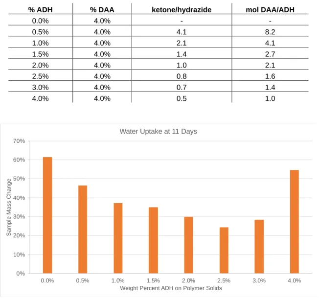
Table 1. Sample composition including molar and stoichiometric ratios of DAA and ADH. Note that 2.0% ADH results in a 1:1 stoichiometric ratio of ADH to DAA based on molecular weight
and functionality. ... 43
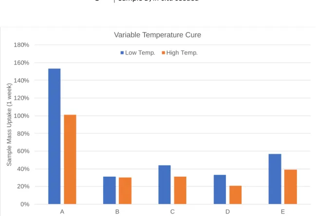
Table 2. These polymers are compositionally identical and were processed using the same methods. Unless otherwise noted, the polymers were prepared using redox initiation, grown on a seed, and are all acrylic. ... 45
Table 3. Polymer samples with Tg values and required coalescent loading. Tg was measured using a TA instruments DSC of neat polymer. ... 46
Table 4. DOE #1 designed to assess the effect of crosslinking, molecular weight, monomer hydrophobicity, and Tg on water uptake. Crosslinking is achieved with DAA monomer and ADH, molecular weight is decreased by addition of 0.5% DDM chain transfer agent, the hydrophobicity is altered by using either styrene or methyl methacrylate as the bulk monomers, and finally the Tg is controlled by changing the ratio of EHA & BA to Styrene or MMA. ... 48
Table 5. DOE data overview. The samples provide a large response range, allowing for easy identification of important factors. The min/max/mean indicate a broad range of performance was achieved. The large variation should permit good differentiation between sample conditions. ... 49
Table 6. DOE samples used for EIS testing. PAM is a 50/50 mixture of PAM A and PAM B ... 65
Table 7. Samples chosen for water whitening (blushing) tests. ... 70
LIST OF FIGURES
Figure Page
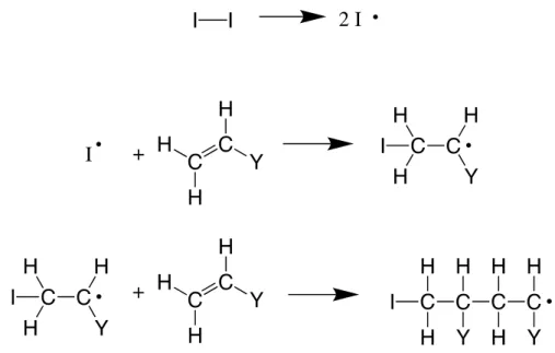
Figure 1. Styrene and polystyrene. ... 4 Figure 2. Initiation and propagation reactions. First some initiator molecule (such as a peroxide) will
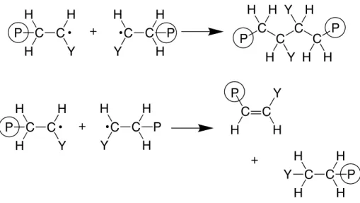
decompose to form two radical species (either thermally driven or using a redox coupling). This radical can then add rapidly to a monomer molecule, resulting in a larger molecule with another radical. This chain reaction then continues to add monomers to the growing molecule, eventually resulting in a polymer chain. ... 9 Figure 3. Termination by combination and disproportionation. Combination occurs when two radical
species add to one another, resulting in radical consumption. Disproportionation occurs when one hydrogen is transferred from one molecule to the other, forming a double bond, and again resulting in radical consumption. Radical species that may participate in these termination reactions can include growing polymer chains or newly formed initiator radicals. ... 10 Figure 4. Diacetone acrylamide (left) & adipic acid dihydrazide (right) ... 24 Figure 5. During film formation ADH reacts with DAA that has polymerized into the backbone, resulting
in a crosslink between two polymer chains. This reaction is acid catalyzed and thus occurs upon evaporation of volatile base (usually ammonia) during film drying. As the reaction proceeds, water is produced as a byproduct and evaporates, further driving the equilibrium to the right. ... 25 Figure 6. The proposed three step process by which water uptake occurs. The film which is clear and
applied to a black substrate is initially submersed in DI water. Upon initial contact with water, water molecules penetrate into the film where there are more hydrophilic functional groups or areas of the polymer. These may include areas where there is a high concentration of surfactant, acid monomer or other polar functional groups. Following this hydration, certain areas continue to absorb more water up to and past the point of saturation. Finally, as these domains grow large enough, they begin to scatter light and the coating slowly turns opaque due to the heterogenous domains of water within the clear coating. Forces acting inside the water “pocket” expand the film, swelling it beyond its starting size and shape, this force is opposed by the polymer matrix resisting expansion. ... 28 Figure 7. Reactor charged with latex seed and water (left). Reactor hot water bath setup (right). Redox
initiators are fed from the graduated cylinders located in the rear of the hood in the left-hand picture. ... 31 Figure 8. Monomer pre-emulsion building process (left). Monomer pre-emulsion complete and ready
for reactor feed (right). ... 32 Figure 9. Monomer pre-emulsion, redox co-feed, and redox charge ready for synthesis. Initiator
charge (front beakers) is added to the reactor, at which point monomer and initiator co-feeds are initiated. This particular setup is for a two-stage polymer, where the second larger emulsion will be fed following the completion of the first. ... 33 Figure 10. A finished emulsion reaction with polymer still in the reactor. At this point the product is
Figure 11. Resins are formulated and then drawn down on release liner or polypropylene sheets.
Following the drying of the film, 1” x 2” samples are cut out and tested. ... 35
Figure 12. After test samples are prepared, they are placed in a jar of DI water and left at room temperature for the duration of the testing time. Periodically the samples are pulled out of the water and patted dry before being weighed and placed back into the jar (left). Samples may absorb varying amounts of water, resulting in variable swelling. ... 35
Figure 13. Films are cut out and placed in the BYK permeability cups. Note that these cups have slightly different designs but perform identically. ... 36
Figure 14. EIS potentiostat. ... 37
Figure 15. Diagram of sample with three electrode setup for EIS. ... 37
Figure 16. Three electrode setup for EIS measurements and depiction of Randles cell circuit. ... 38
Figure 17. PVC effect on the water uptake of a roof coating. Samples are cut out into 1” x 2” coupons, weighed, and submerged in 500mL DI water at room temperature (21 °C) for the duration of the experiment. At each data point the films are removed from the jar, patted dry to remove excess surface moisture, weighed, and returned to the jar. ... 40
Figure 18. The effect of a low VOC coalescing aid on the water uptake of a roof coating. ... 41
Figure 19. The effect of a VOC coalescing aid on the water uptake of a roof coating. ... 42
Figure 20. Water uptake of samples with varying molar ratios of ADH and DAA. ... 43
Figure 21. The effect of coating thickness on the water uptake of a roof coating. ... 44
Figure 22. Water uptake values after a one-week soak at 21 °C. Low temperature film formation was done at 21 °C, slightly above the polymer Tg, and high temperature film formation was done at 50 °C, well above the Tg of the polymer. ... 45
Figure 23. The effect of polymer Tg on the water uptake of a coating. ... 47
Figure 24. Xbar-R chart for one-week water uptake values of DOE polymers. Evaluating the range data (lower graph), where the within subgroup is replicate soak test, outliers have already been removed (n=2 or 3) the measurement system is in control (no points outside the control limits). The mean within-subgroup range is 2.5% which is historically the expected replicate variation. The X-bar graph (upper) shows the ability for the measurement system to detect the between subgroup variation (polymer treatment). Because there is a large range in responses (122%), and a small range in replicate (avg 2.5%) there is a very strong ability to detect performance differences in the samples tested. ... 49
Figure 25. Polymers were synthesized in the run order shown here. There does not appear to be any run order dependence. Films were prepared and measured simultaneously and run order dependence could not be assessed. ... 50
Figure 27. The effect of monomer polarity (MMA vs Styrene) is shown in this main effect plot. As the samples become more non-polar and heavily styrenated, they tend to uptake less water. ... 51 Figure 28. The effect of crosslinking is shown in this main effect plot. As the samples are crosslinked,
they tend to uptake less water than their non-crosslinked counterparts ... 51 Figure 29. The effect of molecular weight is shown in this main effect plot. DDM is shown to have very
little impact on the water uptake of these samples. ... 52 Figure 30. The effect of Tg is shown in this main effect plot, where samples with higher Tg values
tended to perform worse. ... 52 Figure 31. The predicted DDM*XL interaction does not seem to be active in the way predicted, where
lower MW was predicted to facilitate better crosslinking, and uptake resistance. MW data would need to be collected to confirm that this conclusion can be drawn. ... 53 Figure 32. An interaction between monomer polarity and crosslinking was not predicted, however may
be justified due to more similar solubilities of MMA and DAA monomer, resulting in more uniform incorporation of crosslinkable moieties. ... 53 Figure 33. Effect of surfactant amount and type. Non-ionic surfactants resulted in an increase in
performance, similar performance increases were seen when the overall level of surfactant was decreased. ... 54 Figure 34. Polymer before and after dialysis. This serves to further support our conclusion that higher
amounts of surfactant are detrimental to performance. ... 55 Figure 35. Effect of surfactant type and PAM monomer. Non-ionic surfactants performed the best,
followed by reactive anionic, and finally anionic surfactants. And polymers that lack PAM monomers also perform much better than those that contain them. ... 56 Figure 36. Polymer samples with varying loadings of PAM A and PAM B to determine their contribution
to water uptake performance in waterborne resins. ... 57 Figure 37. pH of the monomer pre-emulsion was changed before the polymerization begun. pH values
of 7.0, 5.5, and 4.0 were used respectively as high, mid, and low pH levels. Below pH of 4.0 the monomer emulsion loses stability due to the reduced effectiveness of the anionic surfactant. ... 58 Figure 38. Effect of initiation method on water uptake after 1-week soak in DI water. The 6 samples
differ in their mode of initiation, type of surfactant used, and the loading of phosphate adhesion monomer (PAM). Besides these variables all other compositional and processing variables are kept constant. ... 59 Figure 39. Effect of crosslinking chemistry on water uptake. A difunctional monomer HDODA was
assessed alongside DAA, an intramolecular crosslinking agent that utilizes ADH to form covalent bonds between polymer chains of adjacent particles during the coalescence process. ... 60 Figure 40. Effect of core/shell polymer design on water uptake. Due to its inability to film form, the
Figure 42. This result is identical to those found previously that anionic surfactant is worse for
performance than non-ionic surfactant. ... 63
Figure 43. This result is identical to those found previously that styrene drives improved water uptake performance. ... 64
Figure 44. This result is identical to those found previously that higher degrees of crosslinking drive improved performance. ... 64
Figure 45. Higher capacitance values here correspond to higher water uptake values. Sample 86 was not recorded as the sample failed upon initialization of the test. ... 65
Figure 46. Increased resistance values correlate to increased barrier properties of the coating. The commercial product samples are fully formulated paint coatings and are not ideal candidates for sample comparison. ... 66
Figure 47. Static water contact angles have a loose correlation with uptake values, where larger contact angles drive higher water uptake values. Presumably this is due to waters unfavorable interaction with more hydrophobic polymers as they exhibit higher contact angles. ... 67
Figure 48. Variable water temperature of test samples. ... 68
Figure 49. 5% NaOH caustic water uptake testing. ... 69
Figure 50. Films at 6 wet mils after 24 hours. ... 70
Figure 51. Films at 6 wet mils after 120 hours. ... 70
Figure 52. Films at 6 and 7 wet mils after 24 hours. ... 71
Figure 53. Films at 6 and 7 wet mils after 120 hours. ... 72
1. INTRODUCTION
1.1 Statement of Problem and Purpose of Study
Prior to the mid-20th century, nearly all coatings that were used both at home and industrially were solvent-borne. This included paints, lacquers, and other coatings which were used in nearly every part of the coatings industry. However, with the development and release of Super Kem-Tone latex paint in the 1940s, Sherwin-Williams introduced the homeowner to a water-based paint with myriad advantages over its oil-based counterparts. These paints, as their name suggests, are based on a chemistry centered around using water rather than oil to produce and form a coating.1 The binder that these coatings use are known as latexes or latex resins. The latex is a dispersion of polymer particles in water. Most commonly these polymers are synthesized using free radical polymerization, also known as chain-growth polymerization. However, step-growth polymerization can also be used to synthesize these aqueous dispersions. Polyurethane dispersions, also known as PUDs, are created in this way.1
underlying structure might need to be repaired, and a dissatisfied owner will be on the search for a coating from a different manufacturer.
The purpose of this work is to develop an understanding of what drives water sensitivity and, more specifically, water uptake or absorption in waterborne coatings. Nearly all coatings will encounter water at some point throughout their service life and having some resistance to water is an important factor for end use applications. Water uptake is of interest to coatings and polymer manufacturers for these reasons. Some roofing coatings must meet standards set forth in ASTM D6083 and D471 where a coating free film cannot uptake more than 20% of its mass in water. Many industrial polymers may be used in roofing coatings; however, this is one very important specification that must be met.
There are many factors and variables that can be changed during the synthesis and production of latex resins, as well as formulation of the coatings themselves. Some of these factors are understood, however many are not, and it is the purpose of this study to obtain a more comprehensive understanding of how polymer composition and processing affect water uptake. Acquiring a better understanding of water uptake in latex coatings will allow future development of commercial resins to occur with much more ease and purpose. These conclusions and findings should aid in the evolution of resins used in architectural, industrial, and construction applications.
developing this technology and gaining a more comprehensive understanding of the water uptake phenomenon.
The project is separated into three main stages: understanding the effect of coating formulation, polymer synthesis and design, and the characterization and understanding of the water uptake mechanism and other properties of interest to coatings manufacturers.
Coating formulation- Polymers are tested primarily in neat “formulation-free” systems. However, a series of formulation effects are studied within the scope of roofing formulas, such as pigment loading, coalescent, coating thickness, curing conditions, and non-uniformities in the finished film.
Polymer design- Polymer design is the main focus of the study. Polymers are designed, manipulated, and synthesized to provide an accurate understanding of how compositional and processing parameters affect the performance of the coating. Parameters include Tg, monomer selection, hard/soft dual stage polymers, molecular weight, crosslinking, initiation method, surfactant level/type, and others. The control polymer used for manipulation and study is an altered, simplified version of a current product offered by EPS.
2. LITERATURE REVIEW AND BACKGROUND INFORMATION
2.1 Polymer Basics
Polymer Structure
Polymers are large molecules composed of small building blocks called monomers. The final properties of the polymer are dependent on two things: what the monomeric repeat units are, and how they are put together in the larger structure of the polymer. As one might expect, there are nearly an infinite number of possible monomer combinations, resulting in a vast array of final properties. These polymers are arguably the most important component of coatings and are the driving factor behind many coating properties. They can be synthesized in the lab, as well as found naturally nearly everywhere we look. The former will be the focus of this work, but it is important to understand how abundant these macromolecules are in our day-to-day lives. Oftentimes, polymers are thought only to be rubber and plastic materials; people are very familiar with polystyrene and polyethylene, but the connection is rarely made between the label of “polymer” and everyday things such as cotton, cellulose, protein, and DNA. Some of the most interesting and useful materials human civilization has ever created are polymers, and the field of research pertaining to these materials is immense and growing.
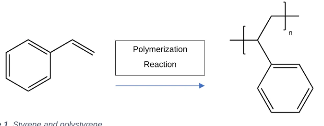
An example is presented below of a simple monomer and resulting polymer structure.
The repeat unit or monomer in Figure 1 is styrene, and the resulting polymer is polystyrene, where n represents the number of repeat units, which can practically range from 100-200 to upwards of 100,000. This is a particularly simplified presentation of a polymer, but it serves to show
Polymerization
Reaction
that the structure of the final product relies nearly entirely on the structure of the monomer. If the monomer is changed, the polymer changes with it.
One of the most fundamental ways to classify polymers is based on chain design and how the chains are oriented in the molecule itself. We can classify most polymers into three categories: linear, branched, and crosslinked polymers. Linear polymers, as the name suggests, are linear macromolecules. The monomer units are joined one after the other and there are no junctions or deviations from the linearity of the chain. The monomer units may be all the same (homopolymers), they may be random combinations of two or more chemically different monomers (random or statistical copolymers), they might be alternating one after another (alternating copolymers) or they may consist of regions of one monomer followed by regions of another, also known as a block copolymers. Branched polymers have periodic branching from the main linear chain. These molecules may have long linear regions but every so often there exists a “fork in the road” where a secondary chain may extend from the primary one. There exist many forms of these polymers, such as graft or comb polymers, but the principle of multiple branches of chains from other chains remains constant. The third class of polymers are known as crosslinked or network polymers. These chains not only have branching, but also covalent bonding of these chains to other molecules in the system. In theory, each and every chain in a crosslinked system may be covalently bound to each other, resulting in one large interconnected molecule. This last class is of extreme importance in coatings applications and is the basis of much research in the field of coatings.
Molecular Weight
One of the most integral and important properties that influence the properties of polymers is their molecular weight (MW). The molecular weight is dependent upon two things: the number of monomeric repeat units that are part of the polymer chain and the type of repeat unit that is used to build the polymer chain. One of the most important characteristics of polymer molecular weights, and something that differs drastically from molecular weights of typical small molecules such as water (H2O: 18.02 g/mol) or glucose (C6H12O6: 180.16 g/mol), is that since there is a distribution of polymer chains in the sample, there is a corresponding distribution of molecular weights.
Naturally, chemists are used to the understanding that a MW is a discrete value dependent upon the number of atoms in the molecule. Each molecule of styrene contains 8 carbon and 8 hydrogen atoms, each having a mass of 12.01 g/mol and 1.01 g/mol respectively (ignoring the effect of isotopes). The sum of these 16 atoms is 104.16 g/mol; the MW of a styrene molecule. However, during a typical polymerization process polymer chains don’t all grow at the same rate. This results in a distribution of long molecules with varying lengths and MWs, centered around some mean value. We refer to this distribution of MWs as a molecular weight distribution. One consequence of this MW distribution is the presence of different average values: the number average molecular weight and the weight average molecular weight. These are defined below:
Number average:
𝑀
̅
𝑛=
Σ𝑁𝑥𝑀𝑥Σ𝑁𝑥
Weight average:
𝑀
̅
𝑤=
Σ𝑁𝑥𝑀𝑥 2Σ𝑁𝑥𝑀𝑥
on the Mn. Furthermore, the Mw will always be equal to or larger than the Mn for this reason. There exists a relationship between these two values which helps us understand this right skewed distribution of polymer chains: the polydispersity index.3
Polydispersity Index (PDI):
𝑃𝐷𝐼 =
𝑀𝑤𝑀𝑛
Notice that since Mw ≥ Mn, the value for PDI will always be greater than 1 in real world samples of polymer. The larger the PDI, the broader the distribution of polymer molecular weights and the more polydisperse the sample is. True monodisperse samples are rare in synthetic polymer chemistry; however, they do exist. A sample of isolated proteins could have a PDI of 1, however carefully controlled synthetic polymers might only be able to achieve PDI values of 1.02 to 1.10. Commercial chain reaction polymers typically have PDIs in the range of 1.5 to 20.3 For samples with exceptionally narrow distributions (and thus small PDI) the Mp value is often reported. This is known as the peak molecular weight and is essentially the mode of the molecular weight distribution.4
It should be noted that there are numerous ways of measuring and reporting molecular weights, such as Z-average molecular weight, viscosity average molecular weight, and using light scattering to measure MW. Some are more accurate, and some are more easily determined experimentally, however a true comprehensive understanding of molecular weight is not paramount to the understanding and execution of this research.
As these molecules flow through the column, the larger ones eventually outpace the smaller ones and elute out of the column and onto the detector before than the smaller chains. Hydrodynamic volume is the technical factor that drives these elution profiles, and here we correlate this hydrodynamic volume to chain length and MW.5
SEC requires much calibration, elution of standards, understanding of sample preparation, and column selection. Branching of the polymer sample will change how the sample behaves and elutes, and effectiveness of the media and solvent also affect how the sample will flow through the column.6 Highly crosslinked samples tend to be nearly impossible to run using these conventional methods due to their low solubility in the solvents used.
2.2 Free Radical Polymerization
Process
There are two commonly accepted classifications of polymerization reactions; step-growth and chain-growth polymerization. The former will not be discussed at length in this paper, though it does account for a large portion of polymers produced and used extensively in our day-to-day lives. Many of our clothing products are constructed from nylon polymers, which are synthesized using a step-growth polymerization reaction.
There are three main steps during the free radical polymerization (FRP) process: initiation, propagation, and termination. A fourth reaction known as chain transfer also takes place that can impact the product of the polymerization. During the initiation phase, the initiating molecule (I) reacts to form one or more free radicals (I·). A free radical then reacts with an available monomer molecule (M), combining the two and forming a new free radical on the monomer (I-M·). The subsequent reactions of this free radical on the monomer molecule with other monomer molecules are called propagating reactions. These reactions grow the polymer chain and take place very fast, resulting in the growth of polymer chains hundreds of units long in a fraction of a second. At any moment during the polymerization process the concentration of monomer and polymer greatly exceed the concentration of growing polymer chains, due to the limited solubility of initiator molecules into the non-polar phase. Since initiation occurs at independent monomer molecules, it is believed that growing polymer particles contain just a few growing chains at any given time. This results in high molecular weight chains being produced very quickly with FRP.7
Figure 3. Termination by combination and disproportionation. Combination occurs when two radical species add to one another, resulting in radical consumption. Disproportionation occurs when one hydrogen is transferred from one molecule to the other, forming a double bond, and again resulting in radical consumption. Radical species that may participate in these termination reactions can include growing polymer chains or newly formed initiator radicals.
The third and final step of the FRP process is termination. Termination reactions are broken down into two categories: combination and disproportionation. A combination reaction occurs when two free radicals, either from initiator molecules, growing polymer chains, or both react together to form a covalent bond. This reaction results in the destruction of two active propagating sites, and the formation of a single “dead” polymer chain. Disproportionation is similar and occurs when two propagating chains meet. Here, the two chains don’t combine, but rather a proton is transferred, and a double bond is formed resulting in the cannibalization of both free radicals. There exists an extensive discussion into the kinetics of FRP, however the content of this discussion extends beyond the scope of this research.3,4
number of chain transfer reactions. Chain transfer reactions usually result in two outcomes: a higher ratio of Mw to Mn (or an increase in PDI), as well as an overall decrease in molecular weight.3
Raw Materials and Processing
As was mentioned briefly, monomers must have either unsaturation or ring structures containing at least one hetero atom such as oxygen or nitrogen. Most of the monomers used in the coatings industry fall into the first category. Most of these monomers which contain unsaturations are alkenes with an electron withdrawing group such as a methyl acrylate and methyl methacrylate. Polymers composed of predominantly acrylic and methacrylic ester monomers are known as acrylic polymers or just acrylics. Styrene is another common monomer used in these reactions.
Initiator molecules or initiators are typically used in the 0.1-4.0 wt.% range. Two main classes of initiators are used in coatings polymers: azo compounds and peroxides. These initiators will decompose to form two radicals when subject to high temperatures or a reducing agent. Initiator selection will depend heavily on the polymer processing that is desired, for example in emulsion polymerization the initiator should be soluble in water and are oftentimes persulfate salts. Persulfate salts such as ammonium persulfate (APS) are very common, and in the case of APS, cleave thermally in water to produce sulfate anion radicals, this is known as thermalinitiation.
in the polymer particles and will help react the remaining monomer that is found inside these particles. The other advantage to using t-butyl hydroperoxide is that there are no remains of persulfate ions following the reaction. It is for this reason that a tBHP redox pair is commonly used as the sole initiator for FRP systems.
2.3 Emulsion Polymerization
Background
One of the most common polymer synthesis processes that utilizes FRP is emulsion polymerization. As one might expect, emulsion polymerization relies on the emulsification of monomer droplets into water throughout the process. This polymerization method can be used with a variety of chemistries, such as acrylic free radical polymerization and polyurethane synthesis to create polyurethane dispersions or PUDs. These systems have many names of varying technical accuracies, such as colloidal dispersions, polymer colloids, latexes, aqueous dispersions, latex emulsifications, etc. We will use the common terms emulsion or latex for the purposes of this paper.
One defining characteristic of latex polymers is that they tend to have relatively high MW when compared to polymers prepared by other means. Polymers exhibiting 𝑀𝑤̅̅̅̅̅ values of 1,000,000 g/mol or higher is quite common. Interestingly enough, the viscosity of the resulting emulsion is not highly dependent on the molecular weight of the polymer, but rather by the volume fraction of polymer to aqueous media in the sample. This is further influenced by particle packing in the emulsion and the size of the individual latex particles. This is key when attempting to create polymers with high molecular weight. Solution polymers with the same MW and solids content as emulsion polymers would be much more viscous. These high molecular weights can result in an increase in durability of the final coating.1
Process
in emulsion polymerization, however the physical circumstances of this polymerization are much different than the FRP of a solution polymer. There are countless parameters and variables that heavily affect both the processing and final product of the polymerization. Temperature, reaction time, pH, feed rate, concentration of surfactant/monomer/initiator, type of surfactant, monomer, initiator, agitation, and solubility of those compounds are just a few of the many important and diverse set of parameters that are variable in this process. The extreme customizability of each component means that it is very difficult to predict the final characteristics of the latex, and that there are innumerable possibilities for both successful and unsuccessful latex products.3
There are two common ways of carrying out an emulsion polymerization process: batch polymerization and semi-continuous polymerization (it is true that continuous reactions are possible as well, but they are not the focus or purpose of this study). Batch polymerization is typically used primarily on small-scale situations, such as in the lab. Here, all of the components necessary are placed into the reaction vessel simultaneously and reacted at once. This method is rarely used on a large scale due to the uncontrollable exotherm and evolution of heat during the reaction. Consequentially, semi-continuous reactor setups are usually the first choice for large-scale production of latex resin. Miniature versions of these industrial-scale reactors are easy to setup in the lab, on a 0.5 to 4-gallon scale, and serve as a good model for eventual production-scale processes. In a semi-continuous reactor, the monomers and other components are added or fed into the reactor at a controlled rate so as to facilitate expeditious polymerization. This is referred to as monomer-starved conditions and allows for very good control of the overall reaction, especially heat production. Furthermore, the composition of the polymer product should theoretically reflect the composition of the monomer feed, all but negating the influence of varying monomer reactivity ratios. This means that the composition of the polymer particle can be influenced by altering the composition of the monomer feed throughout the span of the feed process.8
in-situ seeding. Chemists have used in-situ seeding to produce resins with tight particle size distributions and allows them more control over the average particle size.
A seed is oftentimes used at the outset of the polymerization process to further control variability in the product from one reactor to another. Industrially, a seed is used to minimize batch variability and botched runs, since it is all on the “same” pre-made seed. This seed is essentially a previously prepared infant emulsion, where a small amount of monomer had been initiated and grown into a resin with very small and controlled particle size. These particles then provide the monomer in the main reaction a place to begin the propagation reactions. The utilization of a seed helps control particle size and morphology of the final product for subsequent batches.1,9
Surfactants
Surfactants are molecules not inherently required for FRP, but rather for the physical process of emulsion polymerization. Surfactant molecules contain both a polar head group (hydrophilic) and a non-polar tail group (hydrophobic), and schematically resemble a tadpole. These surfactants are typically non-ionic or anionic, but there exists a vast number of different surfactants, depending on what properties the chemist is looking for. A common example of an ionic surfactant would be sodium lauryl sulfate. Here we can see the anionic head group SO3- as well as the long hydrophobic hydrocarbon chain.
Non-ionic surfactants must still provide a polar region without the use of a charged group. These surfactants provide water solubility mainly via hydrogen bonding. These also exhibit a reduction in water solubility as temperature is increased (driven by a reduction in hydrogen bonding effectiveness) but are less sensitive to water hardness or quality. Ionic surfactants can be affected greatly due to water chemistry.1
with themselves. These micelles typically resemble spheres or rods, with either one or two layers of surfactant molecules. When the monomer is added to this system, the non-polar tails of the surfactant associate freely with the monomer, placing monomer molecules inside the micellar surfactant aggregate. This means that small monomer droplets will be stabilized by the surfactant, resulting in a monomer/water emulsion. The size of the monomer droplets is dependent upon stirring rate, surfactant concentration, and monomer/water ratio.10
Once this emulsion is formed, the initiator can be fed into the system. It is very important that the initiator be watersoluble. The initiator will initiate polymerization as it comes into contact with one of the monomer molecules that happens to be in the aqueous phase. Since the monomer is very insoluble in water, this process is slightly hindered. As the polymer chain grows, surfactant molecules begin to stabilize the chain, and form a small polymer particle. As the process continues, monomer will diffuse out of the monomer droplets and into the growing polymer particle, which grows with each addition of monomer. Surfactant will also join the growing polymer particle to help with stabilization. The monomer droplets shrink until they are gone, at which point all monomer has been converted to polymer, and all surfactant is now associated around the polymer particles, stabilizing the final emulsion product. Termination occurs when a radical, which typically comes from the initiator in the aqueous phase, diffuses into the polymer particle and ends the propagation reaction. This is one of the main reasons that the MW can grow to such great values with emulsion polymerization. It is also beneficial in polymerizing monomers which tend to be much less reactive or terminate too quickly in solution polymerization.8
relies heavily on the surfactant. With poor stability, the polymer particles will approach each other and become held together due to the strong van der Waals forces. This is known as flocculation, which raises the viscosity of the resin, changes the flow to shear thinning and reduces the effectiveness of the resin to be used in coatings. Some systems can be synthesized with surfactant-free systems, however this is atypical and not traditionally used in industrial applications.1,12,13,14
The surfactant stabilizes the particles using two main mechanisms: charge repulsion and outer layer repulsion (comprised of steric, osmotic, and entropic repulsion). Anionic surfactants will be adsorbed along the surface of the particle and orient their anionic salt group outwards toward the aqueous phase. This essentially covers the particle in anions that are then associated with a cation. The layer of cations is known as the Stern layer and behaves as if it were part of the particle itself. The Stern layer then induces the formation of a second layer of anions surrounding it. This double layer of anionic charges causes a repulsive force between any two particles than come near each other. As one might imagine, the presence of salts, especially multivalent ions, can heavily impact the effectiveness of this electrostatic double layer by screening or dampening electronic interactions, which is why water chemistry is more important when anionic surfactants are utilized in the emulsion process.15,16
The hydrophilic nature of the particle surface also results in the adsorption of water, which causes the surface to swell. The thicker this swollen layer of water and surfactant is, the more steric repulsion there will be between two particles, reducing the chance of flocculation.
Additionally, when the water swells these hydrophilic domains of the particles, there exists a large area for the molecules to adopt varying conformations, as water molecules can adsorb and desorb freely. As another particle begins encroaching on this large area, the molecules are limited in the number of conformations they can readily assume. This reduction in entropy results in a resistance to flocculation and a repulsive force known as entropicrepulsion.
phenomenon is called osmotic repulsion. The exact contribution of these three phenomena to the stabilization of the particles is a topic of debate, however, contribution to varying extents of all three is usually accepted.1
2.4 Thermal Properties of Polymers
Glass Transition Temperature
The molar ratio of monomers used in a polymer determine one of the most important properties of the final polymer: the glass transition temperature or Tg. When the temperature of a polymer is raised above its Tg, the polymer transitions from a hard and glassy state to a soft and rubbery state. This is a result of long-range motion of the polymer backbone becoming enabled, meaning that in addition to small vibrations, portions of the polymer chain can move around or slip past one another. The viscosity of thermoplastic polymers falls sub-exponentially as the temperature is further increased above this temperature.17
Fox Equation
Being able to estimate the value of a copolymer Tg is of great importance in polymer development. It is most common to use the Fox equation to derive these theoretical values. Here, w1, w2, w3, etc. are the weight fractions of the monomers present in the copolymer product. Similarly, Tg1, Tg2, Tg3, etc. are the Tg values of their high MW homopolymers.1
1 𝑇𝑔(𝑐𝑜𝑝𝑜𝑙𝑦𝑚𝑒𝑟)
= 𝑤1 𝑇𝑔1
+𝑤2 𝑇𝑔2
+𝑤3 𝑇𝑔3
+ ⋯
A value derived for a copolymer Tg is a theoretical estimation and will vary based on many other factors of the polymerization. It is important to check the actual Tg value following the polymer synthesis, in order to be sure of the Tg value for the sample.
2.5 Latex Film Formation and Coalescence
Film Formation Process
Film formation of latex-based coatings is a much more complicated process than it seems, in fact when paint dries (as exciting as the process may sound), there are many different changes taking place in the coating itself that facilitate the formation of a robust and continuous film. This is a result of the interaction between insoluble polymer particles and the water phase of the system.
more concentrated, so the ionic double layer stability fails at some point during this process. This interdiffusion of polymer chains is the final step in film formation and arguably the most important. If there is poor or no chain diffusion between particles, there is no way for a continuous film to form on the substrate and all coating properties will be either compromised or absent. This chain diffusion is based heavily on the Tg of the polymer but is also influenced by other factors as well, such as the presence of any plasticizer molecules and crosslink density.3,17,18
A drawback to this film formation by particle coalescence is that very high gloss values are typically difficult to achieve, especially when compared to solvent-borne polymers. This is due to two things: first, an accumulation of surfactant on the surface of the film post-coalescence, and second, a non-uniform surface from the remains of polymer particles left behind after non-complete particle flattening. For high gloss values to be achieved, specular reflection is required. Specular reflection occurs when light reflects off of a surface at an angle to the surface normal that is equal to the angle of incidence. The surface roughness resulting from incomplete particle deformation of emulsion-based coatings limits their ability to reach the same level of specular reflection as solution-based coatings.17
Minimum Film Formation Temperature
coalescence of the film will be achieved. However, at temperatures below the MFFT of the coating, film formation will not be achieved and after drying, the coating will most likely flake off and provide no protection or desired properties due to poor particle interdiffusion.17,1
Coalescent Utilization
The film formation paradox is one of the main challenges that chemists and formulators face when developing coatings using latex resins. On one hand, the Tg must be low enough to achieve good coalescence at room temperature, but on the other hand, these low Tg values result in soft films that are often tacky, susceptible to scratches, and suffer additional performance requirements. So, the question becomes how does one achieve a film that is hard enough to withstand abuse, but will also form a continuous film at room temperature?
One of the most effective ways to satisfy both of these requirements is to incorporate a plasticizer or coalescingaid to allow the polymer chains to more easily move past one another and artificially lower the Tg of the polymer. Typically, these coalescing solvents are volatile so after they facilitate coalesce, they evaporate out of the coating leaving behind a hard, durable finished product with a Tg that is higher than room temperature. One of the most widely used coalescent solvents in both industry as well as literature is 2,2,4-trimethyl-1,3-pentanediol monoisobutyrate, or TPM, also known as TexanolTM. The pronounced effect of this coalescing solvent on diffusivity of the film has been shown to increase diffusivity by nearly 4 orders of magnitude when 12 weight percent TexanolTM is added to coatings with MFFT values moderately above room temperature. Three weight percent additions increase the diffusivity factor by one order of magnitude.17
remain low), it must still allow the coating to harden enough for it to perform as intended. The glass transition temperature of the coalescing aid is also important; the lower the Tg the more effective the coalescent will be. Many accept the estimation of coalescent Tg to be 2/3 that of the melting temperature, though this is by no means universally true. And finally, the solubility of the coalescent is also very important. If the solvent is mainly soluble in water (insoluble in the polymer) then it will take much longer for it to diffuse into the particles to effectively encourage coalescence. On the other hand, if the solvent is very soluble in the polymer, then it will readily diffuse into the particle and aid in coalescence, but may remain in the polymer as a plasticizer.17,1
Water Based Coating Formulation Basics
Formulations for water-based coatings can vary greatly, but many of them have very similar components in order to achieve the desired final film properties. These coatings will commonly include pigment, biocide, rheology modifiers, surfactants, dispersants, defoamers, other small additives, and binders. As discussed previously, MFFT and coalescence is a common hurdle for latex based coatings and requiring a coalescent is very common for this reason. Surfactant and dispersant aid in the stabilization of the coating and incorporation of pigments and other additives. Rheology modifiers grant the wet coating desirable flow and leveling properties, pigments provide aesthetic and body to the film, biocides reduce the tendency for biological degradation of the coating both before and after application, and defoamers help with processing of the product. The binder is the polymer which provides many of the final properties of the film, and is the main focus of this report.19,1
PVC and CPVC
Traditionally, weight relationships are what formulators use when designing paints and coatings, but volume relationships with respect to pigments are of more value and fundamental importance. One of the most popular and important ways of quantifying a pigment loading in any system is using the calculated pigment volume concentration, or PVC. The PVC is merely the volume percent of pigment in a dry film. It is important to remember that the PVC should be expressed as a percent, not a volume fraction, and that the PVC of a wet coating is of no interest.
The development of this understanding is credited to Asbeck and Van Loo20, who go on to observe a stark change in film properties above certain PVC values in different coating systems. They called this PVC level the critical pigment volume concentration, or CPVC. The CPVC is defined as the PVC where there is just sufficient binder to provide a completely adsorbed layer around each and every pigment particle. At this PVC, any additional pigment added to the system would not have enough binder to surround the particles, and there would be void spaces in the film. These void spaces will be composed of air, increasing the porosity and affecting other film properties. The CPVC depends on many factors including binder type, pigment type, solids percentage, dispersant usage, and others.20,18
2.6 Emulsion Polymer Crosslinking
There are many methods and available chemistries that can be used to crosslink polymer systems. The decision to use one over the many other options is the prerogative of the chemist or formulator doing the work. These decisions can be driven by innumerable reasons, some of which may include toxicity, efficacy, performance requirements, cost, regulatory concerns, and most importantly, compatibility with the given polymer system. The two crosslinking methods that are used in this study are based on techniques that are both industrially and commercially relevant. There are other methods that could be explored; however, the following are of most immediate interest with respect to the scope of the project.
Interparticle Crosslinking (Keto-Hydrazide Crosslinking)
The development of many mechanical properties for waterborne coatings can usually be enhanced by creating covalent bonds between the polymer chains. We call these bonds between chains crosslinks, and they provide both benefits and considerations when it comes to the overall performance of the film. For example, the film formation process is known to rely heavily on the interdiffusion of polymer chains into adjacent polymer particles. This phenomenon is known as coalescence. If the polymer chains are covalently bound together, it profoundly inhibits the chains’ ability to diffuse and coalesce into a uniform film. Ideally, the crosslinking reaction would take place soon after chain diffusion and coalescence occur, allowing the formation of a film, followed by the hardening and final development of properties.22
Figure 4. Diacetone acrylamide (left) & adipic acid dihydrazide (right)
Polymers containing DAA for the purpose of crosslinking with ADH, are first neutralized to slightly basic conditions with ammonium hydroxide before adding ADH and mixing until dissolved. ADH is a water-soluble compound and thus should remain in the aqueous phase of the emulsion. Upon drying of the film, water evaporates along with ammonium hydroxide resulting in film formation/coalescence and a reduction in pH. As the coating turns acidic, the rate of the crosslinking reaction between the ketone and hydrazide moieties increases. Since the ADH is water soluble and mostly found outside the particle, the vast majority of crosslinking occurs on the outside of the particles and between adjacent particles that have outwards facing DAA rich regions. This is referred to as interparticle crosslinking. Some ADH will have penetrate into the polymer particle and result in intraparticle crosslinking as well, but not on the same scale as interparticle crosslinking. The crosslinking reaction, shown below in Figure 5, is acid-catalyzed and produces water as a reaction by-product. The water continues to evaporate along with ammonium hydroxide as the film finishes curing, and the crosslinking reactions reach completion.22,23
H2N
N H
H N
NH2
O
O O
N H
Figure 5. During film formation ADH reacts with DAA that has polymerized into the backbone, resulting in a crosslink between two polymer chains. This reaction is acid catalyzed and thus occurs upon evaporation of volatile base (usually ammonia) during film drying. As the reaction proceeds, water is produced as a byproduct and evaporates, further driving the equilibrium to the right.
Intraparticle Crosslinking (Difunctional Monomer Crosslinking)
2.7 Water Whitening and Blushing
Coating plasticization is caused by small molecules such as water intercalating themselves between the polymer chains in a coating. These small molecules facilitate the movement of polymer chains around one another, aiding in coalescence before and during film formation, but detract from beneficial mechanical properties post film formation. Water often plasticizes films, especially after having been submerged for extended periods of time. Water will tend to associate with polymer films in one of three ways: either as freezing free water, freezing bound water, or as non-freezing bound water, the latter being heavily associated with water that contributes to plasticization of a polymer sample.24 These three water-polymer interactions can be studied using DSC, and developing an understanding of the relationship between the polymers Tg, waters Tg, and the plasticized or wet Tg of the polymer with non-freezing bound water. The plasticization of polymer films is a direct result of this non-freezing bound water associating with polar moieties along the backbone of the polymer chain. This artificially lowers the Tg of the polymer by allowing the chains to move past each other with more ease. 25,26,27,28
2.8 Current Mechanistic Understanding of Water Uptake
Figure 6. The proposed three step process by which water uptake occurs. The film which is clear and applied to a black substrate is initially submersed in DI water. Upon initial contact with water, water molecules penetrate into the film where there are more hydrophilic functional groups or areas of the polymer. These may include areas where there is a high concentration of surfactant, acid monomer or other polar functional groups. Following this hydration, certain areas continue to absorb more water up to and past the point of saturation. Finally, as these domains grow large enough, they begin to scatter light and the coating slowly turns opaque due to the heterogenous domains of water within the clear coating. Forces acting inside the water “pocket” expand the film, swelling it beyond its starting size and shape, this force is opposed by the polymer matrix resisting expansion.
3. MATERIALS AND METHODS
3.1 Materials
All materials and precursors are provided by Engineered Polymer Solutions and The Sherwin-Williams Company. All materials are used as provided from the manufacturer without any further processing unless noted in the methods or results sections. These materials are sourced from many suppliers, all of which are not to be listed in this paper. The films and polymer test specimens are all prepared using a semi-continuous emulsion polymerization process. Monomers used include styrene, methacrylic acid, acrylic acid, n-butyl acrylate, methyl methacrylate, butyl methacrylate, ethyl hexyl acrylate, diacetone acrylamide, 1,6-hexanediol diacrylate, acetoacetoxyethyl methacrylate, phosphate adhesion monomers (PAM monomers A and B), and other un-disclosed monomers. Crosslinking is facilitated using adipic acid dihydrazide. Initiators used include erythorbic acid, t-butyl hydroperoxide, sodium persulfate, and ammonium persulfate. A proprietary iron catalyst solution is also used during polymerization. Surfactants include anionic phosphate ester, non-ionic alcohol ethoxylate, and a reactive anionic co-polymerizable surfactant. Dodecyl mercaptan is the chain transfer agent used. Thickener used is Acrysol RM-12W, a non-ionic urethane thickener for development of low-shear viscosity. Acticide MV, Acticide MBS, and Acticide M 20 S are used as biocide additives. A 30.0 wt.% seed latex of undisclosed composition and ammonium hydroxide are also used.
3.2 Methods
Emulsion Polymerization
run between 80-85 °C using ammonium persulfate as the charge and co-feed initiator, and erythorbic acid and TBHP are used as the chase initiators.
Figure 7. Reactor charged with latex seed and water (left). Reactor hot water bath setup (right). Redox initiators are fed from the graduated cylinders located in the rear of the hood in the left-hand picture.
Figure 8. Monomer pre-emulsion building process (left). Monomer pre-emulsion complete and ready for reactor feed (right).
Figure 9. Monomer pre-emulsion, redox co-feed, and redox charge ready for synthesis. Initiator charge (front beakers) is added to the reactor, at which point monomer and initiator co-feeds are initiated. This particular setup is for a two-stage polymer, where the second larger emulsion will be fed following the completion of the first.
Figure 10. A finished emulsion reaction with polymer still in the reactor. At this point the product is filtered through a 100-micron filter into the jugs (left). A series of completed polymer resins (0.5 gallons) awaiting testing (right).
Film Preparation and Water Uptake Gravimetric Analysis
Figure 11. Resins are formulated and then drawn down on release liner or polypropylene sheets. Following the drying of the film, 1” x 2” samples are cut out and tested.
Figure 12. After test samples are prepared, they are placed in a jar of DI water and left at room temperature for the duration of the testing time. Periodically the samples are pulled out of the water and patted dry before being weighed and placed back into the jar (left). Samples may absorb varying amounts of water, resulting in variable swelling.
Film Preparation and Permeability Testing
incorporation of the thickener. The coating is then drawn down in triplicate on polypropylene sheets and allowed to dry at room temperature (21 °C) and 50% RH for one week. Following the one week dry, the films are peeled off the substrate and cut into circles the diameter of the BYK permeability cups. After filling the cups with 10 mL of DI water, the film is placed on the cup between two gaskets and sealed tightly with the threaded cover ring. After weighing the cup, it is placed in a temperature humidity-controlled chamber at 20 °C and 50% RH for 24 hours before being reweighed using a Sartorius Entris 64-1S analytical balance. From the DFT and 24-hour mass difference the specific moisture vapor permeability can be determined.
Figure 13. Films are cut out and placed in the BYK permeability cups. Note that these cups have slightly different designs but perform identically.
Electrochemical Impedance Spectroscopy
Counter
Electrode
Reference
Electrode
Working
Figure 14. EIS potentiostat.
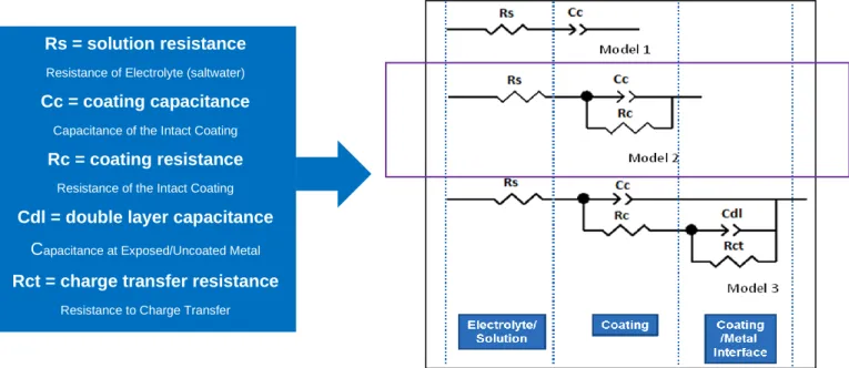
A small sinusoidal potential of 5-10 mV is applied to the open circuit potential at varying frequencies. Phase lag and the current response for varying applied frequencies is measured by the instrument. The data is then modeled using Randles cell circuit to obtain values of coating resistance and coating capacitance.
The two parameters of interest are coating resistance (also known as pore resistance) and the coating capacitance. Coating resistance is the resistance of the coating to uptake incoming water and ions. The magnitude of this resistance is indicative of the coatings state of degradation at any given time. The three timepoints used for data collection are 30 minutes, 24 hours, and 1 week after exposure. Coating capacitance relates to the total amount of water currently in the coating. Due to the solution’s increased conductivity than the coating binder, as the water uptake increases, the capacitance will increase. The following formula is used to help calculate a value for coating capacitance or Cc.
C
c= ϵϵ
0A/d
Here, ϵ is the dielectric constant of the coating, and ϵ0 is the permittivity of free vacuum. A is the exposed area of the coating to the salt solution and d is the thickness of the coating. Any Rs = solution resistance
Resistance of Electrolyte (saltwater)
Cc = coating capacitance
Capacitance of the Intact Coating
Rc = coating resistance
Resistance of the Intact Coating
Cdl = double layer capacitance
Capacitance at Exposed/Uncoated Metal
Rct = charge transfer resistance
Resistance to Charge Transfer
step changes or rapid increases in the coating capacitance value indicates that delamination of the coating may have occurred.
Contact Angle Measurements
The polymer sample is drawn down in triplicates on 4” x 8” aluminum Q-Panels at a wet film thickness of 4 mil. The coatings are 50% solids resulting in a ~2 mil DFT. These samples then dry for 7 days at room temperature (21 °C) and 50% RH for one week. Following sample preparation, the static water contact angle of the coating is measured using a Kruss DSA-30 instrument.
Differential Scanning Calorimetry
One gram of the polymer is put into an aluminum weigh pan and allowed to dry for 24 hours at room temperature (21 °C) and 50% RH. Approximately ten milligrams of the polymer sample is then cut off and placed into a tared DSC pan. This value is recorded into the TA Instruments Trios software. The sample is then run using the following procedure on a TA Instruments Discovery DSC25 with an RCS90 cooling system in order to obtain the Tg value of the polymer.
1. Equilibrate to -75 °C
2. Ramp to 150 °C at 10 °C/min (serves to reset any thermal history of the polymer) 3. Equilibrate to -75 °C
4. Ramp to 150 °C at 10 °C/min
4. RESULTS AND DISCUSSION
4.1 Effects of Coating Formulation and Formation
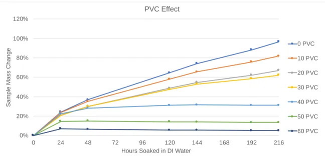
PVC
The same control polymer was used to prepare 7 coatings with the same formulation but varying PVC levels. The coatings all used a 1/7 ratio of TiPure R-960 (titanium dioxide pigment) and Drikalite (calcium carbonate pigment). The 7 coating samples had PVC levels of 0, 10, 20, 30, 40, 50, and 60 PVC, with all formulation factors remaining constant. A master grind paste was made and added to 7 letdowns in different amounts before being drawn down at 40 wet mils. It was seen that water uptake decreased uniformly as the PVC was increased, and these results are plotted in Figure 17.
Figure 17. PVC effect on the water uptake of a roof coating. Samples are cut out into 1” x 2” coupons, weighed, and submerged in 500mL DI water at room temperature (21 °C) for the duration of the experiment. At each data point the films are removed from the jar, patted dry to remove excess surface moisture, weighed, and returned to the jar.
The decrease in water uptake here is attributed to the decreased volume fraction of polymer in each sample with higher pigment loading levels. The pigment particle is not able to expand and absorb water in the same way that the polymer matrix in the coating can. Water molecules instead adsorb onto the surface of the pigment particle, where polymer adsorption is
0% 20% 40% 60% 80% 100% 120%
0 24 48 72 96 120 144 168 192 216
S a m p le M a s s C h a n g e