FUNDAMENTAL STUDIES OF TERNARY BLENDS FOR BULK HETEROJUNCTION SOLAR CELLS
Mary Allison Kelly
A dissertation submitted to the faculty of the University of North Carolina at Chapel Hill in partial fulfillment of the requirements for the degree of Doctor of Philosophy in the
Department of Chemistry
Chapel Hill 2017
Approved by:
Joanna Atkin
James Cahoon
Sergei Sheiko
Scott Warren
iii ABSTRACT
MARY ALLISON KELLY: Fundamental Studies of Ternary Blends for Bulk heterojunction Solar Cells
(Under the direction of Wei You)
Organic photovoltaics have risen to prominence in the last twenty-five years, with
efficiencies broaching 12 %, but the inherent limitation of a narrow absorption window has
restricted the performance of these solar cells. Ternary blends offer an attractive solution to this
conundrum: combining the extended complementary absorption of a tandem solar cell with the
ease of single-junction fabrication. Parallel-like bulk heterojunctions (PBHJ) not only exhibit
improved current, but a tunable voltage, which is a promising development. However, the
development of such ternary blends is still largely an empirical process.
In this dissertation, we investigate the guidelines for material selection for ternary blend solar
cells. We begin by ascertaining the importance of backbone structure for compatibility in PBHJ
OPVs. It immediately becomes clear that to obtain a working PBHJ, a common donor moiety is
required in the polymer backbone. We build on this by comparing the performance and behavior
of a physically fluorinated vs. chemically fluorinated system. In this case, the characteristics of
both blends are nearly identical, indicating that compatible, miscible polymers will behave
similarly to their random copolymer. Additionally, this study highlighted that the addition of a
high mobility polymer into a PBHJ can improve the hole mobility and fill factor. Finally, we
used these guidelines to selected high performance polymers for use in PBHJs and tested their
iv
significantly from that of the copolymer, demonstrating the complexity of ternary blends. What
v
ACKNOWLEDGEMENTS
My thanks go out to the many people who have made this great endeavor possible.
To my advisor, Dr. Wei You, for his guidance, patience, and support. I have had incredible
opportunities for personal and professional development, and grown so much under his
leadership. His unfailing optimism and enthusiasm has served to drive more projects than are
included here.
To my committee, Dr. Joanna Atkin, Dr. James Cahoon, Dr. Sergei Sheiko, and Dr. Scott
Warren, for their time and guidance in this effort.
To Dr. Liang Yan, who has been an amazingly kind, patient, and knowledgeable mentor from
day one. To Qianqian Zhang, who made every single one of the polymers presented in this work;
she is my favorite. To the past and present members of The You Group, for the many stimulating
and entertaining conversations, some of which were even about research.
To my RGC family, for demonstrating God’s love in a million very real ways these past five
years.
To my parents, for modeling insatiable curiosity and teaching me the skills to assuage it, and
for always supporting me in this science nonsense. To my family, for supporting me since I first
started geeking out about chemistry in high-school.
To Sam, Mark, Matt, and Kate, for unending emotional support and hugs, virtual and irl.
To Margy, you can always be the Shawn to my Gus.
vi
TABLE OF CONTENTS
LIST OF TABLES ... xi
LIST OF FIGURES ... xii
LIST OF SYMBOLS AND ABBREVIATIONS ... xv
INTRODUCTION ... 1
1.1 A Brief History and Background of Organic Photovoltaics ... 1
1.1.1 Device Architecture ... 2
1.1.2 Materials Selection ... 4
1.1.3 Morphology ... 5
1.2 An Introduction to Ternary Blends ... 5
1.2.1 Mechanisms of Charge Generation in Ternary Blend Solar Cells ... 6
Charge Transfer Mechanism ... 7
Energy Transfer Mechanism ... 9
Parallel-like Transfer Mechanism ... 9
1.2.2 Tunable Voc in PBHJs ... 10
vii
COMPATIBLE BACKBONE STRUCTURE MOTIFS FOR DONOR POLYMERS IN
PARALLEL-LIKE BULK HETEROJUNCTION SOLAR CELLS ... 12
2.1. Introduction ... 12
2.2 Results & Discussion ... 15
2.2.1 Polymer Properties ... 15
2.2.2 UV-Vis of Ternary Blends ... 16
2.2.3 Device Performance ... 17
Blends with a Common Donor Moiety ... 17
Blends with a Common Acceptor Moiety ... 20
Blends with no Common Moiety ... 23
2.2.4 Energy of the CT State ... 28
2.2.5 Morphology ... 31
Surface Energy ... 32
SIMS ... 33
STXM ... 34
2.3 Conclusion ... 38
2.4 Experimental Section ... 39
Device Fabrication ... 40
viii
3.1 Introduction ... 42
3.2 Results and Discussion ... 46
3.2.1 Electrochemical and Optical Properties ... 46
3.2.2 Device Performance ... 48
3.2.3 Open Circuit Voltage and CT Energy ... 50
3.2.4 Free Charge Carrier Recombination ... 53
Steady State Recombination ... 53
Transient Non-Geminate Recombination ... 54
3.2.5 Electron and Hole Mobility ... 56
3.2.6 Morphology of Three 50% F blends... 58
3.2.7 Performance of HTAZ:FTAZ Physical Blends ... 59
3.3 Conclusion ... 61
3.4. Experimental Section ... 63
Space charge limited current (SCLC) Device Fabrication ... 64
Transmission Electron Microscopy Measurement ... 64
TDCF and BACE Measurements ... 65
EXPLORING ROUTES TO HIGH EFFICIENCY TERNARY BLENDS ... 66
4.1 Introduction ... 66
4.2 Results and Discussion ... 68
ix
4.2.2 UV-Vis of the Blends ... 69
4.2.3 Device Performance ... 72
Short Circuit Current of the Blends ... 72
Open Circuit Voltage of the Blends ... 73
Fill Factor of the Blends... 74
Power Conversion Efficiency ... 75
External Quantum Efficiency... 76
4.2.4 Energy of the CT State ... 78
4.2.5 PyCNTAZ:monoCNTAZ Devices ... 79
4.2.6 PyCNTAZ: 4’FT-FTAZ ... 81
4.3 Conclusions & Future Work ... 83
4.4 Experimental Section ... 85
Device Fabrication ... 85
CONCLUSIONS AND FUTURE WORK ... 87
5.1 The Importance of This Work ... 87
5.1.1 The Importance of Backbone Structure in Ternary Blends ... 87
5.1.2 Improving FF: PBHJ vs. Copolymer ... 88
5.1.3 Towards High Performance Ternary Blends ... 88
x
5.2.1 Ternary blends with Three Absorbers ... 89
5.2.2 Focusing on Morphology... 89
5.3 Final Thoughts... 90
APPENDIX A: CHAPTER 2... 92
APPENDIX B: CHAPTER 3 ... 98
APPENDIX C: CHAPTER 4 ... 116
xi
LIST OF TABLES
2.2 Surface energy measurements including contact angles and free surface energy ... 32
3.1 PV Performance for the H:F physical blends as well as the four polymers of interest ... 49
3.2 Charge Transfer State Energy and Open Circuit Voltage Losses as denoted by Δ ... 52
3.3 Hole and electron mobilities as measured using SCLC ... 57
4.1 Device performance of 200 nm thick PyCNTAZ:monoCNTAZ ternary blends ... 80
xii
LIST OF FIGURES
Figure 1.2 a) Representative energy levels for the donor and acceptor in an OPV with the charge transfer (CT) state highlighted.b) A schematic
of the conventional device configuration used in this thesis ... 3
Figure 1.3 Example of two complementary organic chromophores covering
the solar spectrum. ... 6
Figure 1.4. Schematic of the three mechanisms of charge generation in a
ternary blend solar cell ... 7
Figure 2.1 Structures, energy levels, and bandgaps for the polymers used
in this study ... 15
Figure 2.2 UV-Vis spectra of the four polymers used in this study. ... 16
Figure 2.3 UV-Vis spectra of two PBHJ ternary blends: a) ND:NH
without PC61BM, and b) BD:ND with PC61BM. ... 17
Figure 2.4. PCE and Voc of the PBHJs where the polymer pairs share a
common donor moiety ... 18
Figure 2.5 EQE spectra as measured for the two ternary blends with a
common donor acceptor. a) BD:BH and b) ND:NH ... 19
Figure 2.6 PCE and Voc of blends with a common acceptor moiety ... 21
Figure 2.7 EQE spectra of the ternary blends with a common acceptor
moiety. a) BD:ND and b) BH:NH ... 22
Figure 2.8 PCE and Voc for the ternary blends without a common moiety ... 23
Figure 2.9 EQE for the ternary blends with no common moiety in the
polymer pair. a) BD:NH and b) ND:BH ... 25
Figure 2.10 White light biased EQE for working ternary blends (a) and
xiii
Figure 2.12 Measurements of the high sensitivity, low-energy EQE for
a) BD:BH, b) ND:BD, c) BD:NH and d) BH:NH ... 30
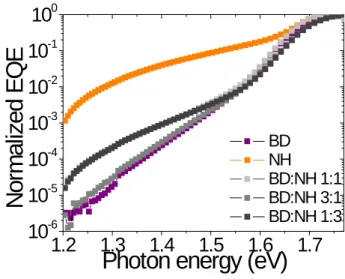
Figure 2.13 Measurements of the high sensitivity, low-energy EQE for multiple ratios of the BD:NH non-working blend ... 31
Figure 2.14 SIMS depth profiles for the BD:BH and BD:ND blends ... 34
Figure 2.15. STXM composite analysis of the BD:BH 1:1 ternary blend ... 35
Figure 2.16. STXM composite analysis of the BD:ND 1:1 ternary blend ... 35
Figure 2.17. STXM composite analysis of the BD:NH 1:1 ternary blend ... 36
Figure 2.18 STXM line scans for the measured blends in 1:1 ratios ... 37
Figure 3.1. a) Three different systems with 50% F content in the active layer. F50 is the random copolymer with m:n being 1:1; due to the asymmetry of the monomer, monoFTAZ, the regular polymer, yet has two different orientations along the backbone; FTAZ:HTAZ is a physical blend that has two polymers at 1:1 weight ratio. b) Representative J-V curves for the 50% F blend solar cells. ... 47
Figure 3.2 Energy levels of relevant polymers and PC61BM... 47
Figure 3.3. External quantum efficiency of the photocurrent and the electroluminescence for all three systems. Gaussian fits to the spectra are shown as red dashed lines and the external quantum efficiency of the photocurrent calculated from the emission spectrum is shown as gray lines. ... 50
Figure 3.4 Differential decay of the total charge carrier density extracted in the TDCF experiment plotted versus the collected charge carrier density ... 55
Figure 3.5. TEM images of the thick (~200 nm), device relevant films. Bright field (zero-loss) of a) H:F 1:1, b) monoF, and c) F50, and sulfur maps of d) H:F 1:1, e) monoF, and f) F50 generated from the standard three-window method. ... 59
xiv
Figure 4.1 Structure and properties of FTAZ and monoCNTAZ ... 68
Figure 4.2 UV-Vis spectra for FTAZ and monoCNTAZ as measured
on a film cast from TCB onto glass substrates. ... 69
Figure 4.3 UV-Vis spectra for the monoCNTAZ:FTAZ blends measured from devices ... 71
Figure 4.4 Short circuit current as a function of percent FTAZ in the blend
for multiple thicknesses. Open markers represent the copolymers. ... 73
Figure 4.5 Open circuit voltage as a function of percent FTAZ in the blend
for multiple thicknesses. Open markers represent the copolymers. ... 74
Figure 4.6 Fill factor as a function of percent FTAZ in the blend for multiple
thicknesses. Open markers represent the copolymers... 75
Figure 4.7 Power conversion efficiency as a function of percent FTAZ in
the blend for multiple thicknesses. Open markers represent the copolymers. ... 76
Figure 4.8 EQE of all of FTAZ, monoCNTAZ, the PBHJs and the copolymers. ... 77
Figure 4.9 ECT as a function of % FTAZ for the PBHJs and the copolymers. ... 78
Figure 4.10 Structure of PyCNTAZ with the UV-Vis spectra of PyCNTAZ
and monoCNTAZ based devices ... 79
Figure 4.11 The structure of 4’FT-FTAZ and UV-Vis spectra of 4’FT-FTAZ,
PyCNTAZ and their ternary blend devices. ... 82
Figure 4.12 The mobility as measured by SCLC for 4’FT-FTAZ, PyCNTAZ,
xv
LIST OF SYMBOLS AND ABBREVIATIONS
BHJ bulk heterojunction
BnDT benzo[1,2-b:4,5-b’]dithiophene
BT benzothidiazole
CT charge transfer
CV cyclic voltammetry
diCNTAZ poly (benzo[1,2-b:4,5-b’]dithiophene
2-(2-butyloctyl)-4,7-di(thiophen-2-yl)-2H-benzo[d][1,2,3]triazole-5,6-dicarbonitrile)
DOS density of states
ECT energy of the charge transfer state
EQE external quantum efficiency
ET' energy transfer
FF fill factor
FTAZ poly (benzo[1,2-b:4,5-b’]dithiophene fluorinated
2-alkyl-benzo[d][1,2,3]triazole)
HOMO highest occupied molecular orbital
HTAZ poly (benzo[1,2-b:4,5-b’]dithiophene
2-alkyl-benzo[d][1,2,3]triazole)
HTL hole transport layer
ITO indium tin oxide
Jsc short circuit current
η efficiency
LUMO lowest unoccupied molecular orbital
monoCNTAZ poly (benzo[1,2-b:4,5-b’]dithiophene
2-(2-butyloctyl)-4,7-di(thiophen-2-yl)-2H-benzo[d][1,2,3]triazolemonocarbonitrile)
monoFTAZ poly (benzo[1,2-b:4,5-b’]dithiophene
dithienylmonofluorobenzotriazole)
MPP maximum power point
xvi
OPV organic photovoltaic
P3HT poly(3-hexylthiophene)
PBHJ parallel-like bulk heterojunction
DTBT 4,7-di(thiophen-2-yl)benzolthiadiazole
PC61BM phenyl-C61-butric acid methyl ester
PC71BM phenyl-C71-butric acid methyl ester
PCE power conversion efficiency
PCPDTBT poly(cyclopentathiophene-benzothiadiazole)
PEDOT:PSS poly(3,4,-ethylenedioxythiophene):poly(styrenesulfonate)
PID2 poly-3-oxothieno[3,4-d]isothiazole-1,1-dioxide/benzodithiophene
Pin input power
PSR photospectral response
PTB7 polythieno[3,4-b]-thiophene/benzodithiophene
PyCNTAZ poly (benzo[1,2-b:4,5-b’]dithiophene
2-(2-butyloctyl)-4,7-di(thiophen-2-yl)-2H-[1,2,3]triazolo[4,5-c]pyridine-6-carbonitrile)
RSoXS resonant soft x-ray scattering
SIMS secondary ion mass spectrometry
STXM scanning transmission x-ray microscopy
UV-Vis UV-Vis spectroscopy
1 CHAPTER 1 INTRODUCTION
1.1 A Brief History and Background of Organic Photovoltaics
In 1992 Alan Heeger and coworkers demonstrated ultrafast electron transfer between a
conjugated polymer and a fullerene.1 Three years later they introduced the concept of a bulk
heterojunction and organic photovoltaics were catapulted into the race for renewable energy
technologies.2 Organic photovoltaics (OPVs) serve as an inexpensive, flexible, light-weight
alternative to the silicon solar cells currently on the market. In addition, the synthetic range
available in conjugated polymers and semi-conducting small molecules affords key tunability in
materials design.3 In the past twenty-five years, OPVs have made great progress towards
industrially relevant performance, growing from ~1% power conversion efficiency (PCE) to over
12%.4–7 This is a direct result of the concerted efforts of chemists, physicists, and engineers to
design and synthesize innovative materials, understand the fundamental mechanisms behind
charge generation, and optimize a carefully engineered device structure.8
The key figure of merit when characterizing an OPV device is the power conversion efficiency
(PCE) (Equation 1.1).
𝑉𝑉𝑜𝑜𝑜𝑜×𝐽𝐽𝑠𝑠𝑜𝑜×𝐹𝐹𝐹𝐹
𝑃𝑃𝑖𝑖𝑖𝑖 =𝑃𝑃𝑃𝑃𝑃𝑃 (1.1)
Jsc is the short circuit current (the maximum current), Voc is the open circuit voltage (the
maximum voltage), fill factor (FF) is the difference between the theoretical maximum power point
2
charges), and Pin is the input power (typically 100 mW/cm2 at 1 sun AM 1.5 conditions) (Figure 1.1). Each of these is highly dependent on the intrinsic properties of the materials used and the processing conditions of fabrication.
Figure 1.1 Representative J-V Curve for an OPV device characterization. The solid-green rectangle represents the position of the theoretical maximum power point. The dotted rectangle represents the area of the actual maximum power point. Fill factor is the dotted rectangle divided by the solid rectangle.
1.1.1 Device Architecture
The active layer of an OPV device is typically composed of two materials: an electron donor
and electron acceptor. Due to the low dielectric constant and high disorder of organic
semiconductors, the excitons generated in these materials are Frenkel excitons, with a binding
energy higher than that of thermal energy at room temperature (~26 meV). To separate the bound
electron-hole pair, a second component is introduced, forming an energy offset that drives charge
3
Figure 1.2 a) Representative energy levels for the donor and acceptor in an OPV with the charge transfer (CT) state highlighted.b) A schematic of the conventional device configuration used in this dissertation.
Organic semiconductors benefit from high absorbance coefficients, which means the active
layer can be relatively thin (~100-200 nm). However, the exciton diffusion length for these
materials is on the order of 10 nm, limiting the thickness of a bilayer device and thereby
restricting absorbance. In order to circumnavigate these limitations, the bulk heterojuntion was
introduced.2 In this case the electron donor (typically a conjugated polymer) and the electron
acceptor (typically a fullerene derivative like [6,6]-phenyl-C61-butyric acid methyl ester,
PC61BM) are codissolved into solution and spuncast into thin films, resulting in a
phase-separated, interpenetrated network of polymer and fullerene domains (Figure 1.2b). The active layer is now no longer limited in thickness by the diffusion of excitons, assuming that the
domains are an appropriate size (~20-40 nm). The donor phase serves as transport for holes,
while the acceptor phase transports electrons. This bulk heterojunction is incorporated into a
typical device structure, presented in Figure 1.2b. Indium tin oxide (ITO) is often used as the transparent bottom electrode, and a hole transport layer (HTL) is added between the ITO and the
active layer to improve electrode selectivity and contact. Calcium serves as an electron transport
layer, and the reflective top contact is air stable aluminum.
4 1.1.2 Materials Selection
During initial research efforts, poly(3-hexylthiophene) (P3HT) quickly emerged as a front
runner in donor materials. This semi-crystalline homopolymer with a bandgap of 2.0 eV served
as the main focus of the field for several years, reaching an efficiency of ~5 %.9 However, the
wide bandgap and high energy levels limited the efficiency of P3HT. The Voc is determined by
the energy of the charge transfer state (ECT), minuses losses due to radiative and nonradiative
recombination. The ECT is related to the difference between the lowest unoccupied molecular
orbital (LUMO) of the acceptor and the highest occupied molecular orbital (HOMO) of the
donor. Thus the ideal polymer will have a low bandgap (to maximize absorbance and Jsc) and a
low HOMO level (to maximize Voc), while still providing sufficient energy offset to drive
formation of the CT state. For example, when paired with PC61BM the ideal polymer would have
a bandgap of 1.5 eV and a HOMO level of 5.4 eV.10,11 To accomplish this, a “weak donor-strong
acceptor” motif was suggested, where an electron rich “donor” moiety and an electron poor
“acceptor” moiety were combined within the conjugated polymer to form a D-A copolymer.11
These D-A copolymers have since dominated the field in high performing polymers based
devices.5,12,13
PC61BM and other fullerene derivatives are nearly ubiquitous as electron acceptors due to
their compatible morphology and energy levels, superior electron delocalization, and relatively
high electron mobility. For many years, polymer design and synthesis focused on creating
polymers compatible with PC61BM,3 but recent developments in high performing non-fullerene
acceptors (NFAs) have opened up new avenues for OPV improvement.5 This dissertation
focuses on OPV devices which utilize fullerene derivatives, but NFAs will be addressed in the
5 1.1.3 Morphology
The morphology of a BHJ is a finely tuned, kinetically trapped, metastable state. While
morphology has always been an important parameter in bulk heterojunction solar cells, our
understanding of it has become increasingly complex in the past years. The mixed phase, and
interplay between domain purity, crystallinity, and domain size are play a crucial role in
facilitating efficient charge generation and extraction.14,15 For example, relatively small, pure
domains have been shown to have a positive correlation to improved FF.16 But the presence of a
third, mixed fullerene-polymer phase has risen to prominence in recent years.14 Materials with a
high degree of order and good π-π stacking typically exhibit high carrier mobility, which is
beneficial for charge extraction. But these materials can also crystalize so extensively that they
do not form small enough domains for exciton diffusion. Therefore, a delicate balance is required
when optimizing the morphology of a BHJ. Morphology can be controlled either by employing
specific synthetic designs (for example, using short, branched side chains to encourage
appropriate packing),17 or by changing fabrication conditions (changing solvents, utilizing vapor
or thermal annealing, or employing high boiling point additives).
1.2 An Introduction to Ternary Blends
One of the inherent limitations of organic materials is their narrow absorption window. This
leads to energy loss via two mechanisms: photons below the bandgap are not absorbed by the
material at all, while photons above the bandgap that are absorbed lose energy by thermalizing to
the band-edge prior to dissociating.18,19 Tandem solar cells are one way to overcome this
limitation. By fabricating sub-cells from two different materials with complementary absorbance,
stacking them on top of each other, and linking them in parallel or in series, a wider range of the
6
cells require careful engineering of several transparent interlayers, leading to a difficult
fabrication. Ternary blend solar cells side-step this limitation by combining the second,
complementary absorber into the active layer with the original donor and acceptor.20–22 This third
component can be a small molecule sensitizer, polymer donor, or additional acceptor.20–22
Ternary blend solar cells can be fabricated in a single junction, bypassing the complexity of their
tandem counterparts.
Figure 1.3 Example of two complementary organic chromophores covering the solar spectrum.1
1.2.1 Mechanisms of Charge Generation in Ternary Blend Solar Cells
With the addition of a third absorbing component, the mechanism of charge generation
becomes more complicated. There are three main mechanisms in ternary blends: charge transfer,
energy transfer, and the parallel-like or alloy model (Figure 1.4).21,23
7
Figure 1.4. Schematic of the three mechanisms of charge generation in a ternary blend solar cell.2
Charge Transfer Mechanism
In the charge transfer mechanism the third component is a donor material which absorbs
light and generates excitons (the sensitizer). These excitons are then split at the interface with the
acceptor (or first donor) and the electron is transported through the acceptor domain. However,
the free hole is then transferred to the first donor, which constitutes the main hole-transport
material. Because of this, the Voc of a ternary blend undergoing mainly charge transfer will be
pinned by the highest HOMO level (lowest Voc) of the two donors. In order for this mechanism
to be successful, the energy levels of all three components must be carefully engineered in a
cascade to facilitate charge transfer.23,24 This mechanism can differ greatly depending where the
sensitizer is located within the blend: at the interface between donor and acceptor, embedded
within the donor phase, or embedded within the acceptor phase.23
8
For example, Koppe et al. used poly(cyclopentathiophene-benzothiadiazole) (PCPDTBT) as
an IR sensitizer to extend the absorbance range of a P3HT:PC61BM blend.25 Using
photolumiscence quenching and photoinduced absorption, they demonstrated that excitons
generated on PCPDTBT split at the PCPDTBT:PC61BM interface, but that free holes were then
transferred to the P3HT for transport to the electrodes. These additional charge carriers led to an
increase in current and efficiency. However, at ratios higher than 20 wt % PCPDTBT, the
second polymer disrupted the formation of favorable crystalline domains in the P3HT, leading to
a drop in fill factor that could not be compensated for by the increase in photocurrent.
In 2014, Lu et al. demonstrated improved efficiency in a ternary blend which incorporated
10-30 wt% poly-3-oxothieno[3,4-d]isothiazole-1,1-dioxide/benzodithiophene (PID2) into a host
blend of polythieno[3,4-b]-thiophene/benzodithiophene (PTB7) and PC71BM.24 At 10 wt% PID2,
performance improved from a Voc of 0.72 V, Jsc of 15.0 mA/cm2, FF of 67.1 %, and PCE of 7.25,
to a Voc of 0.72 V, Jsc of 16.8 mA/cm2, FF of 68.7 % and PCE of 8.22%. While some of this
improvement stemmed from an increase in absorbance with the addition of PID2, they also argue
that the cascading energy levels of PID2 facilitated charge transport in the blend. This was
exhibited in the improved current generation from PC71BM as measured by EQE, and by the
improved recombination and hole mobility. Measuring the morphology via TEM, 2D GIWAXS
and RSoXS showed that the addition of PID2 leads to the formation of favorable fibrils and
smaller fullerene domains. While the pinned Voc, and photolumiscence (PL) behavior make it
clear that this blend operated mainly as a charge transfer mechanism, rather than an energy
9 Energy Transfer Mechanism
In some blends, the added sensitizer generates excitons but does not split them to form free
charges for charge transport. Rather, the absorbed energy is transferred to the host donor via
Forster or Dexter energy transfer, for which the emission of the sensitizer must overlap the
absorbance of the donor.21,26 The additional excitons which are then generated on the donor are
split and transported as normal. This mechanism is evidenced when measuring PL of the blend of
sensitizer and donor: the donor should quench the PL of the sensitizer while the sensitizer
increases the PL of the donor. This was observed in a recent study (also by Lu et al.), where
PID2 was added to a blend of PTB7-TH and PC71BM.27 However, as evidenced by the
composition dependent Voc, ET was not the only mechanism at play. ET is especially promising
since when paired with singlet-fission it has the potential to pass the theoretical efficiency
limit.21
Parallel-like Transfer Mechanism
Interestingly, both CT and ET dominated ternary blends are limited by a pinned Voc. In
2011, Yang et al. reported a ternary blend that exhibited composition dependent Voc: the Voc
increased as a function of the polymer ratio.28 Because of this, and the additive behavior of the
Jsc of the binary “subcells,” the authors labelled this a “parallel-like” bulk heterojunction (PBHJ).
In a PBHJ each donor functions independently: generating excitons, splitting them at the
acceptor interface, and transporting charges. Earlier that same year, Khlyabich et al. reported
similar behavior between a ternary blend showcasing two fullerene acceptors.29,30 They
postulated this was due to the fullerene derivatives forming an “electronic organic alloy,”
10
Barry Thompson’s group went on to show similar behavior in several polymer:polymer
pairings.31–33
1.2.2 Tunable Voc in PBHJs
There has been some debate regarding the origins of the tunable Voc in PBHJs. Barry
Thompson’s group has consistently presented blends with a tunable Voc under the alloy
model.29,31,33 Lu et al. also reported a blend with a tunable Voc, and due to the apparent
cocrystalization of the polymers argued that the alloy model was more likely.27 However, Liu et
al. reported a ternary blend between one donor and two acceptors with tunable Voc where the two
acceptors clearly formed different domains, supporting the parallel-like model.34
From a theoretical perspective, Kouijzer et al. modeled the CT state of a PBHJ ternary blend
as either the average of two separate CT states (PBHJ) or an alloyed CT state (alloy model) and
compared it to experimental data.35 The model of the two-state system agreed best with the
experimental data, but could not completely reproduce the Voc trends, indicating that the PBHJ
model was still lacking. Felekidis et al. points out that the presence of a metal contact enforces
quasi-Fermi level pinning, meaning that the sub-cells cannot be treated independently, but the
alloy model would require extreme delocalization of the CT state in blends with a reported 1:9 or
9:1 ratio.36 They suggest rather, a quantitative framework from modeling the density of states
(DOS). In this model, strongly overlapping DOS will lead to an almost linear Voc trend, whereas
HOMO levels which are farther apart will exhibit a sublinear dependence of Voc with
concentration. Additionally, they show that for state-of-the-art absorbers with a wide, strong,
absorbance, ternary blends offer little theoretical improvement unless the charge transport is
11
Savoie et al. suggested a model which not only took into account the distribution of states
leading to Voc, but the possibility that differential light absorption would affect the occupation of
those states.23 Their model agreed well with experimental results. They also suggested that
miscible pairs of donors (or acceptors) would adversely affect the Voc, since it would encourage
molecular contact and facilitate carrier equilibration between the pairs.23 However, it has been
demonstrated that polymers with similar surface energy (and therefore miscibility) are more
likely to show this tunable Voc.33,37,38 Given the nuances of the discussion, it is clear that such
blends are incredibly complex and it may require several models to fully capture their
characteristics. Additionally, two systems with similar trends in device performance may have
very different underlying mechanisms.
1.3 Motivation for This Dissertation
Given the complexity of ternary blends: the multiple pathways for charge generation, the
variety of “ideal” morphologies, and the active debate regarding appropriate models, studies
investigating the fundamental nuances of working and nonworking ternary blends are paramount.
Ternary blends have the potential to overcome one of the chief limitations OPVs: the narrow
absorption window. But adding a third component to any already delicately balanced
two-component system introduces several degrees of complexity. The material options for the third
component are almost limitless, and at present, discovering a good ternary blend is still too
dependent on “guessing and checking.” Understanding what makes two donors compatible:
12
CHAPTER 2
COMPATIBLE BACKBONE STRUCTURE MOTIFS FOR DONOR POLYMERS IN PARALLEL-LIKE BULK HETEROJUNCTION SOLAR CELLS
2.1. Introduction
Ternary blends are used to extend the absorbance, often by adding a complementary
sensitizer in small volumes. In many cases, the hole transport occurs predominantly through
only one of the materials, pinning the Voc to the highest HOMO level. A parallel-like bulk
heterojunction (PBHJ), in contrast, is marked by two distinct characteristics: the Voc evolves as a
function of blend composition and the blending ratios are relatively high ( >20%).20,21 In 2011,
proof-of-concept for the PBHJ was demonstrated by two concurrent studies. Yang et al.
introduced two ternary blends based on four donor-acceptor type copolymers
(PBnDT-DTBT:PBnDT-HTAZ and PBnDT-DTPyT:PBnDT-DTffBT), both of which showed improved
performance over the control binary blends.28 They made ternary blends at ratios of 3:7, 1:1, and
7:3 by weight and, with both pairings, the Voc shifted as a function of composition: from the
lowest binary Voc to the highest. This was contrary to expectation, since in previous ternary
blends the Voc had been effectively pinned by the highest HOMO level of the two donor
materials, limiting the Voc to the lowest of the two values.25 The Jsc of the 100 nm thick PBHJ
was equivalent to adding the Jsc of the two 50 nm reference “subcells” of the binary blends, and
13
cell. Independently yet concurrently, Ojala et al . a similar affect by co-evaporating C60 and two
merocyanine dyes.39
Around the same time, a series of studies from the Thompson group explored what they
called an “organic alloy” ternary blend. Two systems, a ternary blend with two fullerene
acceptors and a ternary blend with two P3HT based donor polymers, both exhibited a tunable
Voc.29,30,40 Street et al. measured the CT energy of this blend using PSR and found that it shifted
in a manner similar to the Voc.40,29 Both the alloy model and the PBHJ model show the same
device characteristics. Previously, the improved absorption of a ternary blend came at the cost of
a pinned Voc , but with this discovery, it is possible to improve Jsc without completely limiting
the Voc.
The distinct Voc behavior and relatively high blending ratios set PBHJs apart from other
ternary blends, but little was known regarding how they worked, or which pairs of donors might
be compatible, yielding improved performance. Based on these examples, as well as other
literature examples of non-PBHJ ternary blends,24,33 two design principles were hypothesized: 1)
that a pair of donors must have similar enough HOMO levels that one would not function as a
trap state within the blend, 2) the pair of donor polymers must have a similar backbone
configuration to ensure compatibility. These design principles were already built into the
previously cited systems, since in Yang et al. all of the polymers featured BnDT as the donor
moiety within the backbone, and in the studies from the Thompson group, the copolymers all had
a 3-hexylthiophene as a significant component of the backbone. Given that ideal phase
separation and morphology are incredibly important for binary BHJs. In a ternary system, this
14
either form complementary but independent domains or their ability to closely interact to create
an electronic alloy) is a key design component.
With this in mind, we chose four polymers which would test the second hypothesis. We
began by synthesizing one of the working pairs from Yang’s paper:
PBnDT-HTAZ:PBnDT-DTBT (synthesized as previously reported28). We then synthesized two additional polymers,
replacing the BnDT unit with NDT (Figure 2.1).41 In this way, we created a series of polymers which could be mixed and matched in a PBHJ to test the importance of a matching backbone
moieties. There are two pairs with matching donor moieties (PBnDT-HTAZ:PBnDT-DTBT and
PNDT-HTAZ, PNDT-DTBT), two pairs with matching acceptor moieties
(PBnDT-HTAZ:PNDT-HTAZ and PBnDT-DTBT:PNDT-DTBT), and two pairings with no matching
moieties (PBnDT-HTAZ:PNDT-DTBT and PBnDT-DTBT:PNDT-HTAZ).
It should be noted that while one of the main motivations behind ternary blends is combining
materials with complementary absorption to improve the performance, the pairings with
matching acceptor moieties have almost completely overlapping absorbance spectra (i.e., both
polymers with DTBT have the same absorbance range). These pairings are unlikely to see
improved performance in that regard, but are included as a control to verify the influence of
polymer compatibility on tunable Voc. Additionally, all of these polymers have fairly similar
HOMO levels as measured by cyclic voltammetry (< 0.2 eV different), so the effect of HOMO
level is not being probed with this study. For simplicity, the polymers will be abbreviated as
follows: PBnDT-DTBT (BD), PBnDT-HTAZ (BH), PNDT-DTBT (ND), and PNDT-HTAZ
15
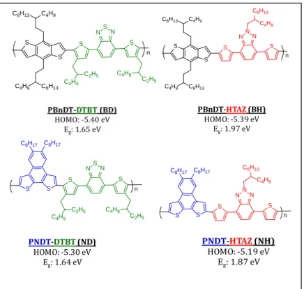
Figure 2.1 Structures, energy levels, and bandgaps for the polymers used in this study.
2.2 Results & Discussion 2.2.1 Polymer Properties
The structures and energy levels of the four polymers of interest are shown in Figure 2.1. As discussed above, each polymer shares a common moiety with two other polymers. The
HOMO levels were taken from the literature, or estimated from cyclic voltammetry.28,41 All
HOMO levels are within 0.2 eV, which should prevent one of the donors serving as a trap within
the blend. Figure 2.2 shows the absorbance of the polymers in question. The bandgap is largely determined by the donor moiety, and both polymers with DTBT (ND and BD) have a bandgap of
1.65 eV. Whereas the HTAZ based polymers have wider bandgaps of 1.86 eV and 1.97 eV. The
S S
C6H13
C4H9
C6H13 C4H9
S S
N N N
n
C6H13
C4H9
S S S N S N
C4H9 C2H5
C2H5 C4H9
S C8H17 C8H17
n S S S N N N S C8H17
C8H17
n
C6H13
C4H9
S S
C6H13
C4H9
C6H13 C4H9
S S
N S N
n
C4H9 C2H5
C2H5 C4H9
PBnDT-HTAZ(BH)
HOMO: -5.39 eV
Eg: 1.97 eV
PNDT-DTBT(ND)
HOMO: -5.30 eV Eg: 1.64 eV
PNDT-HTAZ(NH)
16
complementary bandgaps of these polymers are key to extending absorbance and improving
efficiency.
Figure 2.2 UV-Vis spectra of the four polymers used in this study.
2.2.2 UV-Vis of Ternary Blends
When polymers with different bandgaps (e.g. ND:NH) are combined in ratios: 3:1, 1:1, and
1:3, the absorbance of the blends tracks with the weighted average of the neat polymers: each
contributing individually to the blend spectrum (Figure 2.3a). The long wavelength peaks grow in as the polymer with a smaller bandgap is added into the mix. This is the ideal situation for a
ternary blend, where the goal is to extend the absorbance and limit thermalization loss. Thus we
will expect that the blends with complementary bandgaps are likely to show the highest increase
in Jsc. When donors with similar bandgaps are combined, the blended absorbance spectra are
slightly different. Rather than a clear increase in contribution from a small bandgap polymer at
longer wavelengths, there is a general increase in the absorbance across the spectrum as the
polymer with the stronger absorbance is added. This stems from the difference in absorbance
coefficient (or in some cases, aggregation behavior: BD shows significantly more aggregation
0 0.2 0.4 0.6 0.8 1 1.2
300 500 700 900
N
or
m
al
iz
ed A
bs
or
banc
e (
A
rb)
Wavelength (nm)
17
than ND) (Figure 2.3b). In this case we expect to see less improvement in the Jsc for the ternary blends, but these blends are still of interest as a control, to determine whether a common acceptor
moiety is enough to guarantee compatibility in other ways. UV-Vis spectra for the rest of the
ternary blends in this study are included in the appendix (Appendix A2).
Figure 2.3 UV-Vis spectra of two PBHJ ternary blends: a) ND:NH without PC61BM, and b) BD:ND with PC61BM.
2.2.3 Device Performance
All devices reported herein were fabricated in conventional device stacks of
ITO/PEDOT:PSS/Active Layer/Calcium(50 nm)/Aluminum(100 nm). In each active layer the
overall donor to acceptor ratio was maintained at 1:1 with PC61BM.
Blends with a Common Donor Moiety
The BD:BH blend has been previously reported as a working PBHJ where the optimized
ternary blend (PCE 5.88%) outperformed either of the binary blends (4.06% and 4.39% for BH
and BD respectively).28 In this study, batch to batch variation from the synthesis and changes in
processing conditions led to overall lower performances, and at no ratio does the ternary blend
outperform the BD device (Table 2.1, Figure 2.4). This discrepancy has been seen with other
0 0.1 0.2 0.3 0.4 0.5
300 500 700
A bs or banc e ( a. u .) Wavelength (nm) NDT-DTBT D:H 3:1 D:H 1:1 D:H 1:3 NDT-HTAZ 0 0.2 0.4 0.6 0.8
300 500 700
18
published systems as well, and serves to highlight the delicacy of ternary systems.31,40 However,
the quintessential composition dependent Voc is reproduced in this blend, indicating a
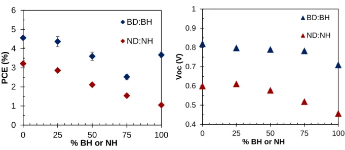
functioning PBHJ (Figure 2.4). Additionally, the PCE is also composition dependent, following a semi-linear trend as the ratio of BH increases. Thus, it is clear that these polymers do not
inhibit each other’s performance in the ternary blend, but both form charge transport networks
effectively making a new solar cell with the average behavior of the parent cells. While we were
not able to replicate the improvement in performance previously published, these polymers are
still compatible. As will be discussed below, it is possible for two polymers to be completely
incompatible: the ternary blends perform significantly worse than either binary blend. This was
not the case here. However, we do not see the improvement in Jsc published previously, which
likely stemmed from enhanced charge transfer and transport between the polymers in the prior
study. Despite these differences, the composition dependent PCE and Voc are clear indications
that these polymers are compatible and form a working PBHJ.
Figure 2.4. PCE and Voc of the PBHJs where the polymer pairs share a common donor moiety.
0 1 2 3 4 5 6
0 25 50 75 100
PC
E (
%
)
% BH or NH
BD:BH
ND:NH
0.4 0.5 0.6 0.7 0.8 0.9 1
0 25 50 75 100
Vo
c
(
V)
% BH or NH
BD:BH
19
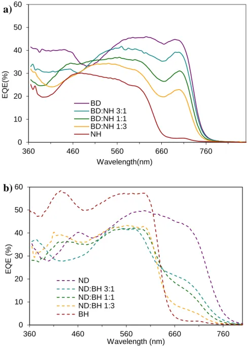
Additionally, it is clear from the EQE spectra of this blend that both polymers are
contributing to the current (Figure 2.5). From 660-760 nm the current increases with increasing BD concentration and from 460-510 nm the EQE exceeds the that from BD alone, indicating that
BH is contributing to charge generation.
Figure 2.5 EQE spectra as measured for the two ternary blends with a common donor moiety. a) BD:BH and b) ND:NH
0 10 20 30 40 50 60
360 460 560 660 760 860
EQ
E (
%
)
Wavelength (nm)
BD BD:BH 3:1 BD:BH 1:1 BD:BH 1:3 BH
a)
0 10 20 30 40 50 60
360 460 560 660 760
EQ
E (
%
)
Wavelength (nm) ND
ND:NH 3:1 ND:NH 1:1 ND:NH 1:3 NH
20
The ND:NH blend was not a part of the previous study, but mirrors the BD:BH blend since in
both pairs the polymers share a common donor moiety. By comparing the performance of these
blends, we are able to ascertain whether this trait is essential to compatible PBHJ polymers. This
is the first time the NH polymer has been synthesized; those details are available in Appendix A1. In a binary blend with PC61BM, NH exhibits particularly low performance, with a PCE of 1.05 %, Voc of 0.456 V, Jsc of 4.19 mA/cm2 and FF of 54.8 % (Table 2.1). Given the overall poor performance, it seems unlikely that adding NH would improve the ND:PC61BM blend (PCE
3.22%), and indeed, no improvement over the top performing binary blend is shown. However,
the ternary blends do exhibit the key features of a PBHJ: composition dependent Voc and PCE
(Figure 2.4). Despite its poor performance, NH does not completely disrupt the ternary blend and both polymers are able to contribute to current generation. In the EQE, the contribution from
ND at 660 – 760 nm grows in as expected (Figure 2.5b). The contribution from NH is apparent since the EQE does not drop substantially from 460 – 660 nm as the amount of ND drops down
to only 25%. This follows the trend previously observed in literature: many working PBHJs have
a common donor moiety. However, the question remains: is any common moiety sufficient? Will a common acceptor moiety also provide enough compatibility?
Blends with a Common Acceptor Moiety
In order to investigate the effect of a common acceptor moiety, we compared the BD:ND and
BH:NH ternary blends. It is important to note that due to the largely overlapping absorbance,
these blends will not exhibit the extended spectra that is a major motivation of ternary blends.
Additionally, it may be difficult to discern in EQE spectra whether both polymers are
21
PCE and composition dependent Voc, which are the hallmark of PBHJs.
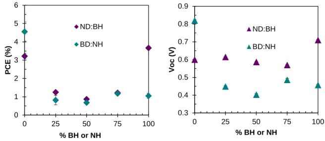
Figure 2.6 PCE and Voc of blends with a common acceptor moiety.
The BD:ND blend was expected to be the better of the pairings, since both binary blends
have performances above 3%. However, at all blending ratios, the ternary blends showed
significantly worse performance than the binary blends, dropping to 0.50, 0.76, and 1.66 %
(Figure 2.6). The Voc also showed no composition dependence (Figure 2.6). Even though these polymers share the DTBT moiety, they do not form a compatible PBHJ. The EQE support the
conclusions drawn from the J-V data as the quantum efficiency is significantly less for the
ternary blends (Figure 2.7). Again, since these polymers have similar bandgaps, it is impossible to deconvolute the contributions from individual polymers in the ternary blends.
The behavior of the BH:NH blend is slightly different in that the PCEs of the ternary blends
are not worse than both binary blends. Rather, the ternary blends seem to be pinned near the
performance of the NH blend. The Voc is similarly pinned, and as soon as NH is added into BH,
the value drop from 0.711 to 0.576 V. While the Voc does vary to a degree with composition, the
trend does not show as linear behavior as the previous PBHJs. And throughout the course of this
0 1 2 3 4 5
0 25 50 75 100
PC
E (
%
)
% BD or NH
BD:ND
BH:NH
0.4 0.5 0.6 0.7 0.8 0.9
0 25 50 75 100
Vo
c
(
V)
% BD or NH
BD:ND
22
project, NH has shown a Voc from ~0.4V to ~0.6V, so small improvement in Voc with the
addition of BH is possibly within error. The EQE spectra agrees with the trends observed with
the PCE measurements, showing only slight improvement in current generation with the addition
of BH into the blends (Figure 2.7). Since there is significant overlap in the spectra, it is not possible to deconvolute which polymer is contributing to the current.
Figure 2.7 EQE spectra of the ternary blends with a common acceptor moiety. a) BD:ND and b) BH:NH.
0 10 20 30 40 50 60
360 460 560 660 760
EQ
E(
%
)
Wavelength(nm) BD
BD:ND 3:1 BD:ND 1:1 BD:ND 1:3 ND
a)
0 10 20 30 40 50 60
360 460 560 660 760
EQ
E (
%
)
Wavelength (nm)
BH
BH:NH 1:3 BH:NH 1:1 BH:NH 3:1
NH
23
So, as with the BD:ND blend, despite having a common acceptor moiety, the BH:NH blend
does not show compatibility. Based on these and the previous two examples, it seems clear that a
common donor moiety, but not a common acceptor moiety, is important for a composition
dependent Voc and PBHJ behavior.
Blends with no Common Moiety
As a final set, the two blends without a common moiety were investigated. For the BD:NH
blend, the PCE of the ternary blends dropped quickly with the addition of NH to the blend (from
~3% to ~1%). The Voc of ternary blends also dropped from 0.82 V to under 0.5 V (Figure 2.8). While the PCE and Voc of the ternary blends were not lower than both binary blends, they were essentially pinned to the values from the NH blend. This behavior mirrors that of the BH:NH
blend, where the ternary blends also were very similar to the NH binary blend. It may be that
without the presence of a common donor moiety, NH will dominate the performance in any
ternary blend it is added to.
Figure 2.8 PCE and Voc for the ternary blends without a common moiety.
0 1 2 3 4 5 6
0 25 50 75 100
PC
E (
%
)
% BH or NH ND:BH
BD:NH
0.3 0.4 0.5 0.6 0.7 0.8 0.9
0 25 50 75 100
Vo
c
(
V)
% BH or NH ND:BH
24
For the ND:BH blend, the PCE of the ternary blends is much worse than either binary blend
(dropping from ~3% to ~1%, Figure 2.8, Table 2.1). Additionally, the Voc is not composition dependent, but hovers near the lower ND value (0.6 V). This in some ways also mirrors the
behavior of the BD:ND blend, where the performance dropped significantly below the
performance of the control binary blends. Thus, without the common donor moiety, the addition
of ND leads to even lower performance in a ternary blend.
Based on these two examples, it is clear that without the common moiety, the PCE will drop
significantly, and not show the averaged behavior of a PBHJ. However, for these two blends, the
Voc did not drop similarly, but rather was pinned near the lowest binary blend (NH and ND,
respectively).
Interestingly, the blends without a common moiety showed particularly divergent EQE
behavior (Figure 2.9). The Jsc of these ternary blends showed little improvement, even at times (in the case of the ND:BH) dropping well below the Jsc from the binary blends (~9 mA/cm2).
The BD:NH blend was only slightly better than the lowest Jsc from the binary blends (~4
mA/cm2). However, the EQE spectra of both of these pairings showed clear contribution from
25
Figure 2.9 EQE for the ternary blends with no common moiety in the polymer pair. a) BD:NH and b) ND:BH.
Since EQE is measured under monochromatic light at lower intensity, it seemed possible that
this was an effect of light intensity. To investigate this, we performed EQE measurements while
the cell was biased with white light in order to determine the quasi-steady state bias-dependent
EQE.42 We measured devices where the Jsc agreed with the EQE (BH binary blend, and BD:BH
0 10 20 30 40 50 60
360 460 560 660 760
EQ
E(
%
)
Wavelength(nm) BD
BD:NH 3:1 BD:NH 1:1 BD:NH 1:3 NH
a)
0 10 20 30 40 50 60
360 460 560 660 760
EQ
E (
%
)
Wavelength (nm) ND
ND:BH 3:1 ND:BH 1:1 ND:BH 1:3 BH
26
blend) and one where it didn’t (ND:BH 1:1 ratio). There was a clear difference in the
white-biased EQE between the working blends (BH and BD:BH) and the nonworking blend (ND:BH
1:1) (Figure 2.10). The poor performance of the ND:BH 1:1 blend, and marked difference between normal EQE and white biased EQE, indicates that significant issues with recombination
in these blends, and a marked changed in conductivity under illumination. This is additional
evidence that the blends without a common moiety are hindered by suboptimal charge transport
conditions.
Figure 2.10 White light biased EQE for a) working ternary blends and b) nonworking ternary blends.
400 500 600 700 800 900
0.0 0.1 0.2 0.3 0.4 0.5 0.6 0.7
BHBD1_5 9.2 mA/cm2
BHBD2_5 9.1 mA/cm2
BH5_2 10 mA/cm2
BH6_2 9.3 mA/cm2
E
QE
Wavelength [nm]
300 400 500 600 700 800 900
0.0 0.1 0.2 0.3 0.4 0.5
2.3 mA/cm2
7.1 mA/cm2
Substrate 6 - Device 2 (ND:BH 1:1)
E
QE
Wavelength [nm]
White Light Bias No Bias
27
Table 2.1 Device Performances for Ternary Blends in this Study.
Polymer Thickness (nm)
Jsc
(mA/cm2)
Voc
(V)
FF (%)
η
(%)
BD 101 9.71 ±0.48 0.820 ±0.004 57.3 ±0.7 4.56 ±0.26
BH 183 9.24 ±0.27 0.711 ±0.004 46.4 ±0.4 3.05 ±0.09
ND 112 9.97 ±0.29 0.600 ±0.003 53.7 ±1.8 3.22 ±0.15
NH 107 4.19 ±0.04 0.457 ±0.003 54.8 ±0.7 1.05 ±0.02
BD:BH 3:1 103 9.66 ±0.49 0.798 ±0.003 56.7 ±1.0 4.37 ±0.22
BD:BH 1:1 124 8.87 ±0.28 0.790 ±0.003 51.4 ±1.0 3.60 ±0.15
BD:BH 1:3 173 7.26 ±0.36 0.783 ±0.002 44.3 ±0.8 2.52 ±0.15
ND:NH 3:1 88 7.75 ±0.16 0.611 ±0.001 60.3 ±0.5 2.86 ±0.08
ND:NH 1:1 108 6.80 ±0.11 0.578 ±0.002 53.7 ±0.9 2.11 ±0.05
ND:NH 1:3 96 5.60 ±0.14 0.519 ±0.002 53.1 ±1.0 1.54 ±0.05
BD:ND 3:1 163 2.82 ±0.07 0.483 ±0.011 37.0 ±0.9 0.50 ±0.03
BD:ND 1:1 150 3.30 ±0.10 0.500 ±0.002 46.0 ±0.3 0.76 ±0.02
BD:ND 1:3 122 5.85 ±0.22 0.548 ±0.004 51.9 ±0.6 1.66 ±0.07
BH:NH 3:1 160 6.36 ±0.44 0.576 ±0.014 39.6 ±0.7 1.46 ±0.15
BH:NH 1:1 166 5.6 ±0.13 0.541 ±0.005 40.2 ±0.5 1.22 ±0.04
BH:NH 1:3 152 5.51 ±0.27 0.53 ±0.004 50.7 ±1.8 1.48 ±0.06
BD:NH 3:1 118 4.77 ±0.33 0.449 ±0.004 38.3 ±0.4 0.82 ±0.05
BD:NH 1:1 120 4.44 ±0.29 0.403 ±0.006 38.3 ±1.1 0.68 ±0.03
BD:NH 1:3 114 4.97 ±0.33 0.496 ±0.008 47.7 ±1.9 1.18 ±0.14
ND:BH 3:1 149 5.28 ±0.34 0.615 ±0.002 38.4 ±0.2 1.25 ±0.08
ND:BH 1:1 160 3.30 ±0.16 0.587 ±0.002 44.7 ±1.4 0.87 ±0.06
28 2.2.4 Energy of the CT State
Since one of the key features of a working PBHJ is the composition dependent Voc, we
decided to investigate the energy of the charge transfer (CT) state using high-sensitivity
low-energy EQE. The low-energy of the CT state has been clearly linked to the Voc.29,35,36
Previously in the literature, ternary blends have shown CT EQE (and therefore CT energy)
between the parent binary blends, with energies following the trend in Voc.29,33 Here we
measured the EQE of the CT state of the binary blends and the 1:1 ratios of four of our ternary
blends: BD:BH, BD:ND, BH:NH, and BD:NH. The trends in Voc for these for blends are
displayed in Figure 2.13. Initially, we expected that for the working blend, BD:BH, the CT EQE the blends would lie roughly in the middle, between the BD and BH CT EQE. There are
relatively few examples of CT EQE measurements for nonworking blends, but it was expected
that the CT energy would be pinned to the CT energy of the lower binary blend.33 Since the CT
energy does not take into account the effect of recombination on Voc, it is possible that a blend
29
Figure 2.11 The trends in Voc with composition for four of the blends, displayed as the percent BH in BD, ND in BD, NH in BH, and NH in BD.
A qualitative analysis of the shape of the CT EQE curves suggests that in each case, the
energy of the CT state heavily favors one of the polymers in the blend (Figure 2.12). In fact, there was no clear difference in the behavior of the working blend (BD:BH) compared to the
other three nonworking blends. The BD:BH blend did not have a CT roughly in the middle, but
rather heavily favored the BD behavior. It should also be noted that although the CT energy of
the blends does appear to be “pinned” to one of the binary blends, it is not always the polymer
with the lower HOMO level. In the BD:BH blend, the CT energy favors BD, which has a higher
HOMO level. Rather, the CT energy of the blend always favors the polymer with the lower
bandgap. This may be due to a difference between the polymers regarding their solubility in
PC61BM. If one of the polymers is more soluble in PC61BM, it will benefit from increased
interfacial area and may dominated the EQE spectra, without leading to enough difference in
charge transport to effect the Voc.
0.3 0.4 0.5 0.6 0.7 0.8 0.9
0 25 50 75 100
Vo
c
(
V)
% BH, ND, or NH
30
Figure 2.12 Measurements of the high sensitivity, low-energy EQE for a) BD:BH, b) ND:BD, c) BD:NH and d) BH:NH all at the 1:1 ratio.
Alternatively, this may be evidence of increased energy transfer between the polymers
(which was previously postulated as a possible means of improved efficiency in these systems.
Often, more than one mechanism can occur in the same ternary blend).21,27,34 Since energy
transfer occurs from the large bandgap polymer to the small bandgap polymer, this would lead to
the blend favoring the CT energy for the small bandgap polymer. Normally, if energy transfer is
the only mechanism in the blend, the Voc is pinned to the Voc of the lowest binary blend.
However, it seems likely that in this case, the energy transfer is in addition to the typical parallel-charge transport, and thus the Voc is not pinned, but the more sensitive low energy EQE
1.2 1.3 1.4 1.5 1.6 1.7 10-6 10-5 10-4 10-3 10-2 10-1 100
a)
N
or
m
al
iz
ed E
Q
E
Photon energy (eV)
BD BH BD:BH
1.2 1.3 1.4 1.5 1.6 1.7
10-6 10-5 10-4 10-3 10-2 10-1 100 ND BD BD:ND
Photon energy (eV)
N
or
m
al
iz
ed E
Q
E
b)1.2 1.3 1.4 1.5 1.6 1.7
10-6 10-5 10-4 10-3 10-2 10-1 100 BD NH BD:NH
Photon energy (eV)
N
or
m
al
iz
ed E
Q
E
c)
1.2 1.3 1.4 1.5 1.6 1.7
10-5 10-4 10-3 10-2 10-1 100 BH NH BH:NH
Photon energy (eV)
31
measurement shows evidence of this additional mechanism. In addition, we measured the 3:1
and 1:3 ratios for the BD:BH blend (Figure 2.13). It is only after increasing the concentration of NH up to 50%, that the CT curve begins to shift towards the EQE spectrum of the NH blend,
confirming the previously presented results.
1.2 1.3 1.4 1.5 1.6 1.7 10-6
10-5 10-4 10-3 10-2 10-1 100
BD NH BD:NH 1:1 BD:NH 3:1 BD:NH 1:3
Photon energy (eV)
N
or
m
al
iz
ed E
Q
E
Figure 2.13 Measurements of the high sensitivity, low-energy EQE for multiple ratios of the BD:NH non-working blend.
2.2.5 Morphology
The morphology of a ternary blend can be difficult to quantify. A typical binary BHJ is a
delicately balanced, kinetically trapped three phase system consisting of a polymer phase, a
fullerene phase, and a mixed phase. Domains must be small enough to guarantee exciton
diffusion to the interface, but large enough to form charge transport pathways. Domains must be
pure enough to reduce recombination, but also provide sufficient interaction with the second
component for exciton splitting. A ternary BHJ must also fit these parameters, but with the
added complications of polymer:polymer interactions. Additionally, since the polymers may
32
with the acceptor. Measuring and analyzing these systems can prove challenging, since often
times, the two polymers involved are difficult to distinguish, given their similar elemental
makeup and structural motifs. Several methods are used here to gain some insight into the
morphology of these systems. Each contributes a glimpse of the complex morphology inherent
to this three component, kinetically trapped system.
Surface Energy
Surface energy has been used as a predictor of polymer compatibility, and is fairly
straightforward to measure on thin films using contact angle measurements for two
solvents.31,38,43 Two polymers with very different Free Surface Energies are less likely to be
miscible, and more likely to yield poor morphology and poor performance.31,43 However, for our
polymers, all four polymers here have very similar surface energies (which are also similar to the
surface energy of PC61BM, suggesting similar miscibility with the fullerene) (Table 2.2). While the differences in morphology may still play an important role in the formation of a working (or
nonworking) PBHJ, it is not apparent using this predictive metric for this case.
Table 2.2 Surface energy measurements including contact angles and free surface energy.
Polymer θ H2O θ DMSO Free
Surface Energy (mN/m)
Blend ΔFree
Surface Energy (mN/m)
BH 103.8 59.26 27.7 BD:BH 2.2
BD 105.76 64.06 25.5 ND:NH 2.8
NH 104.18 59.51 31.0 BD:ND 2.7
ND 105.9 54.77 28.2 BH:NH 3.3
PC61BM33 ---- ---- 27.6 BD:NH 5.5
33 SIMS
One poorly investigated aspect of ternary blends is the possibility of vertical segregation in
the blends. Vertical segregation in binary blends between the polymer and the fullerene is well
documented.44 There is no reason to think that this couldn’t also occur between the polymers in
the blend. The relatively solubility of these polymers in oDCB (the casting solvent) is not
known, so it is possible that one of the polymers will drop out solution more quickly, influencing
vertical segregation. To investigate this possibility, and it’s correlation to device performance
we measured secondary ion mass spectrometry (SIMS) on a working and non-working blend:
BD:BH and BD:ND, respectively. Initial measurements using visual light microscopy indicate
that while both films are rough, the BD:ND film is clearly rougher (Appendix A3), and the roughness of both films may complicate the measurement. We also attempted to use C60 as a
bombardment ion as an attempt to obtain unique molecular fragments, which would enable us to
distinguish between the polymers. Unfortunately, this was not possible, so we were limited to
measuring the polymers:PC61BM stratification.
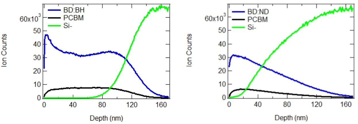
For the BD:BH device, there was some polymer enrichment at the top and the bottom of the
film (Figure 2.14) which is consistent with normal device behavior. Additionally, there was an observable interface with the silicon substrate from 80-140 nm. However, this is not a
particularly clear interface, suggesting non-negligible aggregation blurs the interface with Si.
For the BD:ND device (Figure 2.14), there are no discernable interfaces; signal from the Si gradually increases while the PC61BM and BD:ND signal concurrently decreases. This is likely
due to a combination of the inherent roughness of the film as well as the thin quality of this
particular sample. Such a poor film, with an high aggregation almost creating a “porous”
34
fact that these polymers are able to form binary blends with PC61BM to create successful BHJs,
when paired in a ternary blend, the resulting aggregation leads to poor film formation. While we
were not able to gather meaningful data regarding stratification of the polymers in these blends,
measuring SIMS did provide some understanding of the inherent roughness of these films, and
how that might affect device performance.
Figure 2.14 SIMS depth profiles for the BD:BH and BD:ND blends STXM
Finally, We utilized scanning transmission x-ray microscopy (STXM) to study these systems,
which uses differences in resonance energies to provide materials contrast and image the films.45
We focused on the three blends containing BD, as they showed the most varied performance:
BD:BH, BD:ND, and BD:NH. These represent blends with a common donor moiety, common
acceptor moiety, and no common moiety.
35
Figure 2.15. STXM composite analysis of the BD:BH 1:1 ternary blend
36
Figure 2.17. STXM composite analysis of the BD:NH 1:1 ternary blend
For the BD:BH blend, the BH is drastically anti-correlated to the PC61BM trace, whereas the
BD is correlated with the PC61BM and anti-correlated with the BH. This suggests that the
PC61BM favors mixing with the BD blend, which may in part explain the fact that the CT
energies also favor the BD (more CT states form between BD: PC61BM than between BH:
PC61BM, and dominate the spectra for that reason). The relatively pure BH domains may
facilitate charge transport, but given that the Voc is not pinned to the value of BH (0.706 V), the
BD must play a significant role in charge transport. BH and BD have similar hole mobilities in
the literature,12,46 so it is unclear whether BH would provide added benefits as a transport matrix.
37
Figure 2.18 STXM line scans for the measured blends in 1:1 ratios.
For the BD:ND blend, the polymers are also anti-correlated, forming their own domains.
Again, the PC61BM seems to slightly favor the BD blend. However, this does not agree with the
measurements of the CT energy, in which the blend favored the ND (this is also apparent in the
38
clear, which may contribute to the poor performance of this blend, along with the increased
roughness discussed previously.
For the BD:NH blend, the polymers are slightly anti-correlated, but the PC61BM does not
seem to favor one polymer over the other (this is especially true in the BD:NH 1:3 ratio,
Appendix A4). This is different from the other nonworking blend, where PC61BM seemed to favor the BD. While it is difficult to draw any comparisons between the three blends, the results
suggest that the working blend forms separate polymer domains, whereas the other two
nonworking blends are more intermixed. This suggests that the formation of independent charge
transport pathways may be crucial to the formation of a working PBHJ.
2.3 Conclusion
This study was designed to probe the effect of backbone compatibility on PBHJ behavior,
and to outline guidelines for polymer selection in ternary blends. We did this by comparing the
performance of two blends with common donor moieties (BD:BH and ND:NH), two blends with
common acceptor moieties (BD:ND and BH:NH), and two blends with no common moiety
(BD:NH and BH:ND). Only the blends with a common donor moiety showed both the
composition dependent Voc and the averaged PCE which indicate a working PBHJ. Since
typically the donor moiety of a D-A type copolymer is associated with hole transport—one of the
main duties of the polymer within the BHJ, it makes some amount of sense that these must be
compatible for a PBHJ where both polymers form hole transport networks.
Further investigation of the blends shows that the CT energies do not trend with the Voc, as
has been previously reported for these types of devices.40 Rather, the CT energy of the blend