Design and Development of Harmonics Free Microstrip Band-Stop Resonator Using
Complementary Split Ring Resonator
1V. Shenbagadevi and 2K. Annaram
1Department of electronics and Communication Engineering Kamaraj College of Engineering and
Technology Virudhunagar, India
2Department of electronics and Communication Engineering Kamaraj College of Engineering and
Technology Virudhunagar, India
Abstract: A harmonics rejected microstrip narrowband band-stop resonator using complementary split ring resonator (CSRR) structure is presented in this paper. The proposed harmonics rejected band-stop resonators are first derived from the conventional one with lumped parallel LC resonators. Secondly this lumped resonator is converted as a distributed band-stop resonator. The harmonic rejection ability of this distributed band-stop resonator is improved by embedding CSRR in its ground plane. The proposed design has the advantage of harmonic rejection ability as well as simple to fabricate. Hence the proposed design can be used in harmonics free narrow band transceivers to avoid design complexity. To verify the performance of the proposed design, distributed band-stop resonators are realized using microstrip technology. The experimental results show that in comparison with conventional one which one is not having CSRRs, it has a wide stop-band with high attenuation in the second and third harmonic frequencies and acceptable band-stop frequency response in the fundamental frequency also. The measured and simulated results are in good agreement. Hence, the proposed resonator will be an ideal candidate in future harmonics free narrowband communication systems.
Key words: Resonator, filters, harmonics rejection, complementary split ring resonator, transceiver, stop band, narrow band, microstrip.
INTRODUCTION
design of elliptic or quasi-elliptic filters for channel separation or multiband structures (Mokhtaari et al., 2006; Macchiarella and Tamiazzo, 2005).
Due to the increasing demand for dual band and narrowband operation in modern RF systems, band-pass filters (BPF) and band-stop filters (BSF) have become an essential component. In the past, a variety of BPFs with improved electrical performance and geometrical features has been investigated. These BSFs is known to have attractive features such as simpler design, easier to manufacture, lower cost, compact size and lower insertion loss (Hong et al., 2007; Wolfe, 1972; Hong and Lancaster, 1995; Fork et al., 2006). Hence the main concern is about the design of band-stop as well as band-stop responses. To implement the compact communication systems, an alternative approach to coping with the good band pass response as well as band rejection characteristics. However, to achieve high quality factor (Q) to improve the frequency selectivity of the BPF, in the order of the filter must be higher. This increases the size of the communication system and insertion loss. So, this paper presents compact implementations in microstrip technology for the harmonic rejection purpose. For practical implementation, the band-stop resonators employed are (λ/2) and (λ) microstrip printed lines. The simple combination of open-ended and shunt stubs are used for the easier fabrication. As compared to previous works, the proposed structure achieves better performance with harmonic rejection. The proposed narrowband band-stop resonator has been simulated, fabricated and measured. The measured results are in good agreement with the simulated results. The structure of the paper is organized as follows. Section 2 explains proposed band-stop resonator design. In section 3, the experimental verification of the proposed resonator is discussed. Simulation and measured results are presented in section 4. Section 5 concludes paper.
2. Design Of Proposed Resonator:
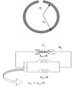
Band-stop resonators provide the resonance frequencies at nfo, where n is the integer number; fo is the center frequency of the resonator. Figure 1 depict a short and open ended transmission line resonators with a length of L=λg/2, respectively. Here λg is the guided wavelength at the fundamental resonant frequency. In order to suppress the second and third order harmonics, CSRR structures are incorporated on the band-stop resonator design.
Structures that are complementary to double split rings were designed and produced by applying the Babinet principle to the split ring resonators (SRR). In this way structures with apertures in metal surface are obtained and these CSRRs create negative ε instead of negative μ in a narrow range near the resonance frequency. In microstrip technology, left handed Meta material structures exhibiting a band stop behavior can be implemented by etching CSRRs in the ground plane, underneath the conductor strip, and along the series capacitive gaps. The gaps provide a negative value of the effective permeability up to certain frequency that depends on gap dimensions and separation. The negative ε structure has been obtained by loading a microstrip line with CSRR particles as shown in figure (1). There are many different parameters that affect resonance frequency of CSRR, most dominant being the permittivity of the substrate and length of the band-stop frequency. The anti-resonance frequency is inversely proportional to the length of the resonator and is directly proportional to the split gap of the resonator. Also, the equivalent circuit of the CSRR is similar to the parallel LC resonant circuit as shown in figure 2. This structure rejects the second harmonics of the fundamental frequency range due to increasing the effective inductance of a transmission line.
Fig. 1: Microstrip loaded CSRR
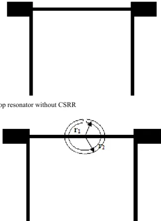
The microstrip narrow band band-stop resonator is realized and CSRR structure is embedded in the ground plane. The layouts of the microstrip band-stop resonators with and without CSRR are shown in figure 3 and 4. The dimensions of the CSRR structures are calculated from the band-stop frequencies. The optimized design parameters of the band-stop resonators are given in Table 1.
Fig. 3: Layout of the band-stop resonator without CSRR
Fig. 4: Layout of the band-stop resonator with CSRR
Table 1: The dimensions of the proposed design
Design
Microstrip line CSRR
Length (mm)
Width (mm) Radius (mm) Width (mm)
r1 r2
Band-stop resonator with
CSRR 19.00 0.600 2.871 4.109 0.861
Fabrication:
To validate the feasibility of the proposed designs, a band-stop resonator with and without CSRR was designed and fabricated on an FR-4 substrate with a thickness of 1.6mm, dielectric constant of 4.5, and loss tangent of 0.00027. The centre frequency of the pass-band is set to 2.45GHz. The operating bands are designed to be centered at the frequency of 2.45GHz and stop-bands frequencies are centered at second and third harmonics of fundamental frequency. The simulation is done in Agilent ADS software. The photographs of the fabricated resonators are shown in figures 5 and 6. It occupies a circuit size of 2.5×1.6cm2.
RESULTS AND DISCUSSION
Fig. 5: Fabricated prototype of band-stop resonator without CSRR
(a) Front side (b) Back side
Fig. 6: Fabricated prototype of band-stop resonator with CSRR
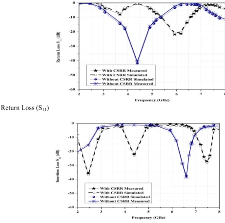
Fig. 7: Return Loss (S11)
Table 2: Performance comparison
Parameters SSimulated Measured 11(dB) SSimulated Measured 12(dB)
Band-stop resonator
without CSRR fo -0.559 -0.409 -14.558 -15.6
2fo -17.322 -16.172 -0.318 -1.318
Band-stop resonator
with CSRR fo -0.253 -0.198 -35.899 -36.884
2fo -3.809 -2.834 -24.795 -23.02
Conclusion:
In this paper, band-stop resonator is designed, simulated, fabricated and tested to operate only at specific frequency 2.45GHz.It is also observed that the proposed designs simulated results are agreed well with the measured one. Traditionally low-pass filter and band-stop filters are used for rejecting unwanted harmonics in narrowband transceivers and multiplexers. So it avoids need of extra components to reject the unwanted harmonics. Hence the proposed design will be an ideal candidate to use in future microwave systems. The results in section IV demonstrate that the proposed band-stop resonator can be successfully employed to implement harmonics free narrow-band communication systems. Moreover, the proposed resonator has a spurious rejection and wide stop-band suppression characteristics. Inherently the proposed design rejects the 3rd harmonics, so we focused only on 2nd harmonic rejection. In future the same technique can be used for the higher order harmonics suppression.
REFERENCES
Chang, C.Y. and T. Itoh, 1991. A modified parallel coupled filter structure that improves the upper stopband rejection and response symmetry, IEEE Transaction on Microwave Theory and Techniques, 39(2): 310-314.
Cohn, S.B., 1958. Parallel coupled transmission line, IRE Transaction on Microwave Theory and Techniques, 6(2): 223-231.
Fork, S.W., P. Cheong, K.W. Tam and R.P. Martins, 2006. A novel microstrip square-loop dual-mode bandpass filter with simultaneous size reduction and spurious response suppression, IEEE Transaction on Microwave Theory and Techniques, 4(5): 2033-2041.
Hong, J.S. and M.J. Lancaster, 1995. Bandpass characteristics of new dual-mode microstrip square loop resonators, Electronics Letters, 31(11): 891-892.
Hong, J.S., H. Shaman and Y.H. Chun, 2007. Dual-mode microstrip open loop resonators and filters, IEEE Microwave Theory and Techniques, 55(8): 1764-1770.
Kim, B.S., J.W. Lee and M.S. Song, 2004. An implementation of harmonic suppression microstrip lines with periodic grooves, IEEE Microwave Wireless Component Letters, 14(9): 413-415.
Kim, I.K., N. Kingsley, M. Morton, R. Bairavasubramanian, J. Papaolymerou, M.M. Tentzeris and J.G. Yook, 2009. Fractal shaped microstrip coupled-line bandpass filters for suppression of second harmonic, IEEE Microwave and Wireless Component Letters, 19(2): 74-76.
Lopetegi, T., M.A.G. Laso, J. Hermandez, M. Bacaicoa, D. Benito, M.J. Garde, M. Sorolla, and M. Guglielmi, 2001. New microstrip wiggly-line filters with spurious passband suppression, IEEE Transaction on Microwave Theory and Techniques, 49(9): 1593-1598.
Macchiarella, G. and S. Tamiazzo, 2005. Design techniques for dual passband filters, IEEE Transactions on Microwave Theory and Techniques, 53(11): 3265-3271.
Mokhtaari, M., J. Bornemann, K. Rambabu and S. Amari, 2006. Coupling matrix design of dual and triple passband filters, IEEE Transaction on Microwave Theory and Techniques, 54(11): 3940-3946.
Sun, S., and L. Zhu, 2005. Periodically nonuniform coupled microstrip line filters with harmonic suppression using transmission zero realocation, IEEE Transaction on Microwave Theory and Techniques, 53(5): 1817-1822.
Velazquez, M.C., J. Martel and F. Medina, 2004. Parallel coupled microstrip filters with ground plane aperture for spurious band suppression and enhanced coupling, IEEE Transaction on Microwave Theory and Techniques, 52(3): 1082-1086.
Wang, S.M., C.H. Chi, M.Y. Hsieh and C.Y. Chang, 2005. Miniaturized spurious passband suppression microstrip filter using meandered parallel coupled line, IEEE Transactions on Microwave Theory and Techniques, 53(2): 747-753.