Volume 75 Annual Issue
Article 35
1968
Pedo-Geomorphic Elements of the Channel and Floodplain of a
Pedo-Geomorphic Elements of the Channel and Floodplain of a
Small Nebraska Watershed
Small Nebraska Watershed
William H. Allen Jr.
Iowa State University
Copyright ©1968 Iowa Academy of Science, Inc.
Follow this and additional works at: https://scholarworks.uni.edu/pias
Recommended Citation
Recommended Citation
Allen, William H. Jr. (1968) "Pedo-Geomorphic Elements of the Channel and Floodplain of a Small Nebraska Watershed," Proceedings of the Iowa Academy of Science, 75(1), 243-252.
Available at: https://scholarworks.uni.edu/pias/vol75/iss1/35
This Research is brought to you for free and open access by the Iowa Academy of Science at UNI ScholarWorks. It has been accepted for inclusion in Proceedings of the Iowa Academy of Science by an authorized editor of UNI ScholarWorks. For more information, please contact [email protected].
Pedo-Geomorphic Elements of the Channel
and Floodplain of a Small Nebraska Watershed
WILLIAM H. ALLEN, JR. 1
Abstract. Pedologic and geomorphic data are combined in this
study in an effort to delineate the areal extent of floodplains and possible extent of overbank flooding. Hydraulically, this procedure may prove most useful in· studying flood routing problems on un-gaged watersheds; however, it may be applied to previously studied catchments in an effort to define more accurately the areas of local-ized inflow and/or major hydrologic changes which may be expected to occur in a down-valley direction.
INTRODUCTION
The use of an integrated systems analysis approach has been adopted by many federal agencies in dealing with watershed performance prob-lems. Hydraulic engineers, soil physicists and scientists, economists, botanists, geologists, and many others are now engaged in a coopera-tive effort to evaluate the potentials of drainage basins. In this paper, pedo-geomorphic, photogrammetric, and hydraulic principles will be presented as they have been applied to the problem of defining the active floodplain and channel system of a selected portion of the Beaver Creek Experimental Watershed near Hastings, Nebraska.
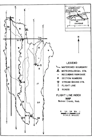
The Beaver Creek watershed, which was operated by the North Central Hydrology Laboratory, Agricultural Research Sevice, U. S. Department o.f Agriculture, is located in the Republican River drain-age basin (Figure 1). It is considered to be representative of the loessial regions of the Central Great Plains. Geologically it is de-veloped in the Lovelancl-Peorian loess complex of Pleistocene age. Beaver Creek itself is an ephemeral stream with the ground-water table occurring at a depth of 40 to 120 feet below the land surface. Mean annual precipitation is 25.4 inches, about three-fourths of it occurring in the late spring and summer from convective~type storms. The mean annual temperature is 50.6° F.
METHODS OF INVESTIGATION
A. Photogrammetric
Low level aerial photographs were used to develop detailed topo-graphic maps. Longitudinal and transverse profiles of the floodplain and channel also were constructed photogrammetically. That portion of the channel which was studied lies between gaging stations W-11 and W-8 (see Figure 1). In this channel re3ich, which has a down-valley distance of 2.23 miles and a downstream distance of 4.21 miles, 141 transverse cross sections were plotted. Cross sections were spaced
lResearch Associate, Department of Agronomy, Iowa State University of Sci-ence and Technology, Ames, Iowa; formerly Hydrogeologist, U. S. Department of Agriculture, A.R.S., S.W.C., Hydrograph Laboratory, Beltsville, Maryland.
244
I'
(" \
IOWA ACADEMY OF SCIENCE
•'
IT
•o
•'
-./'"'1
,•
'
~ \
)
r"
)
I
(
N
1
LEGEND ' - - WATERSHED BOLtlDARYA METEOROLOGICAL STA.
RECOfONG RArNGAGE
I SECTION NUMBERS tp STREAM GAGING STA.
t
FLIGHT LINEI ROADS FLIGHT LINE INDEX
MAP
Beaver Cteek, Neb.
O Vt Ill. !I+ I
SCALE lMILESl
Figure 1. Flight line index map, Beaver Creek, Nebraska.
[Vol. 75
approximately 160 feet apart. The longitudinal profile was determined by the same method. In this case, however, elevations and lateral positions of the thalweg were taken wherever there were marked vari-ations in the general trends.
Data for both sets of information were recorded automatically 'in a rectangular coordinate system by a Benson-Lehner Telacordex unit which was attached to the platen of a photogrammetric plotter.
These ·data provided aocurate and reproducible coverage of the channel cross sections which range between 12 and 39 feet in width. However, it proved to be of limited use on the floodplain because it required relatively close spacing of reading to depict accurately the topographic irregularities. This would have lengthened the machine time and considerably increased the cost.
B. Pedologic
During the early stages of the Hastings project, a detailed soil survey was conducted by the Soil Conservation Service. The soil survey was supplemented by a detailed topographic map of the same scale. Upland soils were distinguished from floodplain soils on the
1968] BEAVER CREEK WATERSHED, NEBRASKA 245
following basis. The upland environment includes summits, shoulders, and blackslope landscape elements from which sediments have been removed by erosion. The summits are assumed to be reasonably stable, while the shoulders and blackslopes have been eroded. The cumulic-fluventic environment is designated as the floodplain element. It in-cludes the. footslope and toeslope landscape forms on which sediments have accumulated. From these two sources (topographic and pedo-logic) the elevation of the "floodplain" soils contact with the "upland" soils was determined. This permitted the delineation of the floodplain extent and general data relative to down-valley gradients, i.e., longi-tudinal valley profiles.
The above surveys (soil and topographic) were conducted in the early l 940's; therefore; from the soils standpoint, they represented only a rough attempt to distinguish differences among the floodplain soils, especially in a down-valley direction. Even in modern day standard surveys, there may be insufficient detail to permit delinea-tion of the colluvial-alluvial soils at the base of slopes from the true alluvial floodplain soils. These problems are not significant in large watersheds, but they do present some difficulties in small watersheds where there have been pronounced topographic modifications resulting either from cultural or naturally induced increases in slope wash and concurrent sedimentation.
C. Geomorphic
Topographic and pedologi,c information are combined under the geomorphic heading in an effort to delineate precisely the potential sites of flooding in a transverse profile, as well. as to permit hydraulic implication to be drawn from the down-valley variations in the gradi-ent and width of the floodplain.
Transverse cross sections were located both above and below those points where lower order channels entered the main channel. Such confluences frequently are points where major changes may be ex-pected to occur in the hydraulic geometry of the main channel. This situation is controlled, in a large part, by the amount of sediment that may be carried into the major channel by the minor one; therefore, the cultural changes such as stock ponds, continuous over-grazing, channel improvements, etc., must be considered also. In the case of the channel under study, most of the causitive forces which . result in width-depth ratio changes could be inferred from a study of the aerial photographs.
RESULTS
A. Pedo-geomorphic
The floodplain soils of the reach under study are represented by the Judson-Wabash-Lamoure complex. A county 'survey which has been completed just recently has established that these series names were
246 IOWA ACADEMY OF SCIENCE [Vol. 75
SC HEMA TIC DIAGRAM OF PEOO-GEOMORPHIC
• ELEMENTS IN BEAVER CREEK STUDY AREA
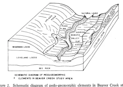
Figure 2. Schematic diagram of pedo-geomorphic elements in Beaver Creek study area.
correlated incorrectly, but the soil mapping units on the ·floodplain
will remain the same. Therefore, the old names are retained in this report. Cain and Beatty ( 2), in a pedo-hydrologic study of certain areas of Wisconsin, use the Judson-Wabash complex in their flood-plain studies, which use indicates the generally recognized relationship between the floodplain on the previous pedologic classification of these soils.
Figure 2 is a schematic diagram of the pedo-geomorphic relation-ships that may be recognized in the Beaver Creek Watershed. Happ, Ritter house, and Dobson ( 6) have described practically the same condition, in which case the zone of study is defined as the normal floodplain, or valley flat, association. It includes the following geneti-cally distinguishable areas: (a) colluvial deposits along the valley sides, (b) vertical accretion deposits, ( c) lateral accretion deposits, (cl) splays along filled channels, (e) trenched tributary valleys, ( f)
channel fill, and (g) alluvial fans.
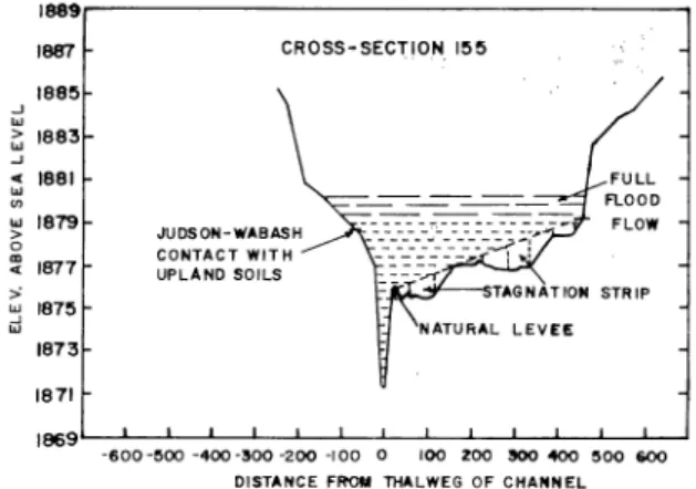
Fourteen transverse cross sections were selected under the premise that the pedo-geomorphic relationships could be used to define the floodplain and thereby the maximum extent of overbank flooding. The data are given for each of the 14 transverses. in Table I. A fairly close relationship exists between the contact of the floodplain soil complex with the back.slope, terrace, and upland soils and the area of expected maximum flooding. Above that point, the valley walls assume the character of the channel banks and the areal extent of flooding is considerably restricted. Figure 3 depicts this situation at one of the cross sections which was studied. For hydraulic purposes, both Table 1 and Figure 3 include not only the pedo-geomorphic data, but also
1968] BEAVER CREEK WATERSHED, 'NEBRASKA
1889~~~~~~~~~~~~~~~~~
..J w
1887 1885 i;'; 1883
..J
"' 1881 w "'
w 1879
>
0
~ 1877
>
~ 1875 1873 1871
CROSS·SEC"[IO.N. 155
JUDSON-WABASH CONTACT WITH UPLAND SOILS
-&oo -eoo -400 -300 -200 -1 oo o 100 zoo 300 400 eoo &00
DISTANCE FR'OU THALWEG OF CHANNEL
HYPOTHETICAL CHANNEL AND FLOOD PLAIN CONVEYANCE SYSTEM
Figure 3. Hypothetical channel and floodplain conveyance system.
247
information pertinent to the hypothetical conveyance system of over-bank flows.
Column 4 in the table shows at what elevations the floodplain soils merge with the upland and terrace soils. Down-valley gradient is computed from these elevations using the valley axis, or minimum direction of overbank flooding, as the down-valley distance. The average difference in elevation between the right bank (natural levee) of the channel and floodplain soil contact with the upland soils is 4.29 feet. That of the left side is 2.98 feet. The down-valley gradient that may be used for overbank flood flows for the entire reach is approxi-mately 0.003 ft./ft. As can be seen from the data (column 9), there are areas in the down-valley gradient computation where the slope is extremely low. These negligible slopes may be expected as the channel thalweg shows similar characteristi.cs which will be discussed in the following section on hydraulic implications.
B. Hydraulic
The above information is required as input data in flood routing programs such as those described by Allen, Dragoun, and Brakensiek ( 1). However, this type of information has been extremely difficult to obtain. Where it has been used, it frequently has been insufficient to define quantitatively the existing flow conditions. The pedo-geomor-phic approach makes it possible to chara,cterize easily the floodplain gradient as well as defi'ne the channel conveyance system in the same study.
Careful attention must be given to the selection of those soils which are supposed to be characteristic of the valley-flat association. Often those soils which occur near the outer edge of the floodplain are not hydraulically related to down-valley overbank flooding, but to the
'~
Table l
.,,.
""Hydrogeomorphic Elements of the Floodplain and Channel Elevation of
Flood-Photo- plain Soil Con tact Floodplain
gram metric Natural Levee with Upland Soil Average Distance
Cross EJevation Elevation Right Left Difference Floodplain Between Channel Floodplain
Section of Right Left Bank Bank in Width Cross Gradient Gradient
No. Thalweg Bank Bank Floodplain Floodplain Elevation (ft.) Sections (ft./100 ft.) (ft./100 ft.)
- · ...
(1) (2) (3) (4) (4-3) (6) ( 7) (8) (4/7) 0
~
(5) (9) >
1 1835.2 1840.4
-
1843.6 1844.0 3.20 420 -· - - >8 183 7 .1 1842.1 1841.4 1845.8 1845.6 3.95 500 870 0.17 0.22 (')
26 1838.5 1843.6 1843.5 184 7 .0 1847.8 3.30 450 840 0.09 0.20 > ti
36 1840.6 1844.5 1845.0 1846.6 1848.0 2.55 650 850 0.20 0.00 trJ
49 1843.0 1847 .3 1847.8 1855.0 1848.4 4.10 500 1115 0.12 0.39 ~
><:
59 1846.6 1851.2 1850.9 1855.o 1855.0 3.95 425 670 0.21 0.49 0
69 1849.9 1854.7 1855.3 1864.0 1855.3 4.65 695 1125 0.17 0.41 "'i
80 1852.4 1856.5 1856.5 1870.2 1859.0 0.16 8.10 780 0.58 850 Ul
95 1854.9 1859.6 1860.1 1863.0 1865.0 4.45 470 1000 0.12 0.00 (') ...
127 1864.5 1869.4 1869.1 1869.6 1882.5 6.80 770 1850 0.20 0.65 trJ 7,
138 1868.7 1872 .2 1872.6 1873.4 1872 .2 0.40 640 810 0.23 0.00 (') tr!
147 1869.7
-
1873.2 1873.8 1874.0 0.80 860 620 0.07 0.17150 1871.6 1875.4 1875.0 1877 .0 1874.5 0.45 570 355 0.33 0.54
155 1871.3 1876.2 - 1879.2 1878.7 3.00 510 820 0.00 0.39
Total 49.70 8240.0 2.07 4.04
Average 3.47 588.57 0.16 0.31
~
~ ~
1968] BEAVER CREEK WATERSHED, NEBRASKA 249
hydraulic regime of the backslopes and low terrace systems. Simon-son ( 7) found this to be true of numerous cases in a study of alluvial soils in the Willow River drainage basin in southwest Iowa. Dietz ( 3) and Fenton (5) found that as many as seven erosional and construc-tional surfaces existed in the Wolf Creek area of central Iowa. Those surfaces that are lower, or closest to the present-day channel, fre-quently have soils developed on them that are closely related morpho-logically to those that exist in the present-day floodplain. Therefore, detailed mapping of the pedo-geomorphic features frequently is re-quired for the proper delineation of the active floodplain.
In the Beaver Creek area, Dragoun ( 4) has shown that the topog-raphy at the base of the slope is mollifying, that is, undergoing con-stant changes due to an influx of sediment which originates as slope wash. Happ, Rittenhouse, and Dobson ( 6) have described a similar situation in the thin loess belt of the Mississippi. This has been de-scribed as postcultural deposition, i.e., that which has occurred since the advent of man into these areas.
Vertical variations in the contact between the upland soils and the valley-flat association probably are a direct reflection of this colluvial influx and its modification of the past, rather stable floodplain geom-etry.
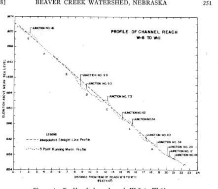
The gradient of the channel is one-half that of the floodplain. This smaller gradient is due to its sinuous and meandering nature. A plot of the channel thalweg's longitudinal profile in shown in Figure 4. Because of the expanded vertical scale, a five-point running mean has been plotted to show the general slope characteristi.cs over an average downstream distance of 7 7 5 feet. A cyclic trend occurs in the profile between 0 and 3 ,000 feet from the head of the reach and also between 8 and 19 ,000 feet. Close inspection of the aerial photographs revealed that at or below those points marked by A, B, and C on Figure 4, the channel length has been shortened by meander cutoffs. This has in-creased the slope considerably by reducing the distance along the channel by as much as a thousand feet. The treads, or flat portions of the profile, lie between 2,500 and 3,000 feet apart with the excep-tion of that reach above 8,000 feet. Meanders also appear to be dis-sected at the same regular intervals. If all the readily observable cutoffs were included in the stream length, the slope would be reduced from greater than 8.5 feet per mile to less than 6.4 feet per mile.
Steep channel slopes occur where the meander pattern is subdued and/or where the channel is straight and parallels the general trend of the floodplain.
It should be noted that those points of localized inflow are indi-cated by junction numbers on Figure 4. It may be coincidence that they are found in those reaches that show an undulatory nature and
250 IOWA ACADEMY OF SCIENCE [Vol. 75
Table 2
Width-Depth Ratio Changes in the Vicinity of Tributary Junctions
Section "Numbers* 9 10 11 16 17 18 19 20 21 33 34 35 42 43 44 53 54 55 61 62 63 72 73 74 92 93 94 98 99 100 140 141 142 Width-Depth Ratio 4.36 4.39 3.20 2.90 3.28 3.35 3.44 4.47 4.00 2.88 2.33 4.52 2.84 4.47 3.54 1.98 5.84 4.33 4.17 2.99 3.20 5.38 Comparative Symbol** L H H L L H L H H L L H L H H L H L H L L H
_ _ _ _ _ _ E_xplanation
Tributary dammed, subsequently broken. Large sediment load still trapped behind dam. Width-depth ratio will eventually be re-versed.
Very small tributary, unrestricted. Enters main channel at a point where there is a lower average channel slope.
Country road acts as flow retardance struc-ture; extensive sediment deposition south of road.
Tributary is dammed.
Tributary unrestricted. Enters main channel at a point where there is a lower average channel slope.
Tributary is dammed.
Minor tributary, dammed.
Meander cutoff; lower entrance to main channel serves as tributary junction; upper limb of cutoff plugged.
Tributary unrestricted; enters main channel at a point where there is a lower average channel slope.
Tributary unrestricted; enters main channel at a point where there is a lower average channel slope.
Tributary is dammed.
*Lower numeral represents downstream section. Middle nuremal indicates loca-tion of tributary juncloca-tion. Higher numeral is upstream secloca-tion.
**L and H are relative symbols referring to low depth ratio or high width-depth ratio, the reference level taken separately for each station where tribu-taries enter the main channel. No value is listed for the middle numeral as it is only a location number and not a cross section.
where they are absent the profile is relatively constant. However, no systematic occurrence is noted in the location of these confluences. Width-depth ratios of the main channel do show the relativ:e influence of these minor channels as may be seen in Table 2. An investigation of the relative width-depth ratios, both above and below these
junc-1968)
,
...
1862
....
....
, . . 0
,
....
....
....
BEAVER CREEK WATERSHED, NEBRASKA
F •
"
'<. ...LEGOID
"·
'<.PROFILE OF CHANNEL REACH
- lOWll
' '
E ·~.~ f;UrrfCTK>N NO. 9 9
·-.>~TIC»tN0.93
·. I'. · ..
'
·. '
D ····.::--, r-=rllN NO. 73
··.,'\.:.._·., ,.
c "';'\.
., r:N0.62
.,
.... ~ .... rJLll'CTlONN0.54
'"~.
·' .. ' .r'UHC!K»rl N0.43 - - - - Interpolated Stioi~ht Line Profile , .l',°',"'-· r'JNClDN NO. 3'4
".I. f'"NCTION NO. 20 A ···•..
1 rucTICJll NO. •7
····'-<..~"""°·' • · '·· • • 5 Point Running Mean Profile
18340~1~,:--~,~.:-~.~.~1----);•----);•---7,;10---+.11---7.12;-7;,.~,.~,.~ •• ~,~1~1•~.~s':--:~~2L1~~"'-,~,-',.
DISTANCE FROM t£AD CF AEAOi w-e TO W-11
ft.ET1:1cf)
Figure 4. Profile of channel reach W-8 to W-11.
251
tions, reveals that where the tributary has been dammed, resulting in a reduced sediment inflow and a longer sustained outflow, the ratio is always lower on the downstream side. Where tributaries enter the main channel under natural conditions, the ratio on the downstream side is always higher, and frequently the channel slope is lower. Sediment delivery in the latter case is higher and the channel is wid-ened to accommodate this influx.
CONCLUSIONS
The accurate delineation of the channel and floodplain geometry can be accomplished most effectively on small ungaged watersheds as well as those that have been gaged for considerable periods of time when pedo-geomorphic, photogrammetric, and hydraulic principles are employed. Aerial photo interpretatfon is also an important aspect of such a study. This type of approach might well be employed in the preliminary stages of selecting watersheds for further intensive study as well as indicating the more desirable sites for location of gaging stations. It also is applicable to urban planning studies where the most efficient use of land areas is desirable and potential flooding hazards must be known.
Although standard soil surveys may be used, research needs fre-quently will dictate the need of more comprehensive information, and a thorough ped6-geomorphic approach will prove desirable and worth-while.
'252 IOWA ACADEMY OF SCIENCE [Vol. 75
AcKNOWLEDGMENT.S
Appreciation is expressed to H. N. Holton, Director, Hydrograph Laboratory, Agricultural Research Service, U. S. Department of Agri-culture, Beltsville, Maryland, for permission to use some of the data
wh~ch the author developed while on assignment in that laboratory. Reviews by members of the Soil Survey Staff, Iowa State University, especially R. V. Ruhe, were helpful in preparation of the manuscript.
Bibliography
1. Allen, W. H., F. J. Dragoun, and D. L. Brakensi.ek. In press. The application of photogrammetric techniques to problems in open-channel hydraulics: U.S.D.A., A.R.S. Series 41.
2. Cain, J.M., and M. J. Beatty. 1968. The use of soil maps in the delineation of flood plans: Water Resources Research, v. 4, pp·. 173-182.
3. Dietz, W. P. 1967. Side-valley cumulic soils in loess areas of Tama County, Iowa: Unpublished master's thesis, Iowa State University of Science and Tech-nology, Ames, Iowa.
4. Dragoun, F. J. 1965. Volumetric erosion and deposition on a complex water-shed: Unpublished master's thesis, Colorado State University, Fort Collins, Colorado.
5. Fenton, T. E. 1966. Soils, weathering zones, and landscapes in the upland loess of Tama and Grundy Counties, Iowa: Unpvblished Ph.D. thesis, Iowa State University of Science and Technology, Ames, Iowa.
6. Happ, S. C., Gordon Rittenhouse, and G. C. Dobson. 1940. Some principles of accelerated stream and valley sedimentation: U.S.D.A. Tech. Bul. No. 695, pp.
1-134.
7. Simonson, G. H. 1960. Genesis of alluvium-derived soils in the Willow River Valley, Iowa: Unpublished Ph.D. thesis, Iowa State University of Science and Technology, Ames, Iowa.