AUTOMATIC COMPUTING MACHINERY
Edited by the Staff of the Machine Development Laboratory of the National Bureau of Standards. Correspondence regarding the Section should be directed to Dr. E. W. Cannon, 418 South Building, National Bureau of Standards, Washington 25, D. C.
Technical
Developments
Magnetic
Drum Storage for Digital
Informa-tion Processing
Systems
Introduction.—Automatic digital computers belong to a class of devices
which may be described by the term "information processing systems."
Some further examples of information processing systems (hereinafter
ab-breviated IPS) are statistical analysis machines, airline reservation tallying
systems, airport traffic control systems, and inventory record systems. A
requisite component of every such device is a storage section which serves
as a repository for a number of separate items of information. These items,
which we shall call "words," may be numerical quantities, alphabetical
material, machine instruction codes, or combinations of these.
In many applications it is required to be able to refer at random to any
word in storage. Each position in storage which may be occupied by a word
is therefore designated by a number called an "address." This type of
in-formation store is analogous to a function table, since to each value of the
argument, or address, there corresponds a single function value, or stored
quantity. In such systems it is necessary to be able to read the word stored
at a given position an indefinite number of times without deterioration of
that word or of its neighbors. It is also generally necessary to be able to
replace or alter the word at a given storage position without disturbing the
contents of neighboring positions. Alterable information storage may be
physically realized in a number of different ways. Well-known examples of
these are electromechanical relays and stepping switches, acoustic delay
lines, electrostatic storage tubes, and various magnetic recording devices.
The choice of storage media to suit a given application is governed by
several considerations. One of these is the degree of physical stability
re-quired of the stored data. In certain applications it is necessary to retain
stored information for extended periods, perhaps for weeks at a time. Under
such circumstances it is a distinct advantage if the retention of data in
storage does not depend on or require the continued operation of electric
circuits. For if the stored information is not "volatile," it is possible to shut
down the equipment for overnight periods, or for the purpose of maintenance,
without loss of data. The combined properties of alterability and
non-volatility are exhibited by very few of the known physical means of storage.
Among these few are stepping switches, latching relays and signals recorded on magnetizable media.
A second consideration governing the choice of storage media is the re-quired capacity, a quantity usually expressed as the number of binary digits or bits of information to be stored. Where large storage is required, the bulky relays and stepping switches present a serious space problem. A two-position
relay is capable of storing only a single binary digit of information, while
32
automatic
computing machinery
With magnetically recorded signals, on the other hand, a large quantity of information may be stored in relatively compact form, as will be shown.
A third consideration is the permissible "access time" or maximum
waiting time which may be tolerated in searching for a given storage position
and reading or altering the word stored there. Many applications require
quick access to any position in the storage. One practical way to satisfy the need for quick random access is to scan the entire mass of stored data
con-tinuously at a rapid repetition rate. In the storage system to be described
information coded in terms of the binary digits 1 and 0 is recorded on a magnetizable medium on the surface of a continuously rotating cylindrical
drum. The small magnetized areas corresponding to individual digits are
arranged in parallel peripheral tracks about the drum. Near each track is a
single stationary magnetic head for reading and writing the digits in that
track. Once in every revolution every magnetized area on the drum is
thereby accessible for the effectively instantaneous operations of reading or
writing. The maximum access time in this instance is equal to the rotation
period of the drum.
The information is recorded in binary coded form so that it is necessary
to distinguish between only two magnetic states for each elemental area.
There is no need for over-all linearity of the recording and reproducing
processes. Specifically, these two magnetic states correspond to positive and
negative magnetization of the medium in a direction parallel to its motion.
The binary coding requirement imposes no limitation on what may be stored,
since information of any kind is readily expressed in a "1 — 0" or "on-off"
code. Thus, decimal digits may be recorded as 4-digit binary code groups,
and alphabetical characters may be recorded as 5- or 6-digit binary groups.
This technique is commonly used in telegraphic systems and in electrical
computing devices.
It is the purpose of the present paper to describe a practical method for
the alterable, nonvolatile storage of information. For applications requiring
these properties, the magnetic drum storage system provides what is felt
to be a reasonable balance of the factors: access time, storage capacity, and bulk and cost of equipment.
Utilization of the Storage Surface.—Each word appears on the drum
surface in parallel rather than in serial fashion. That is, each binary digit of
a 30-digit word, for example, is represented by a single elemental magnetized
area, or "cell," in each of 30 separate tracks, rather than by 30 cells in one
track. As the drum rotates, the 30 digital cells representing one word pass
simultaneously under the magnetic heads in their respective tracks. If each
track should contain 4000 digital cells around its circumference, then a group
of 30 tracks would store 4000 30-digit words. Several such groups of tracks may be needed to provide the required storage capacity.
The number of elemental areas per track and the number of groups of
tracks on a drum are determined by the storage requirements of the applica-tion. Suppose that it is desired to store W words of b binary digits each, with maximum access time of T milliseconds. Let R represent the standard scanning rate, i.e., the number of digital cells passing a given magnetic head in a millisecond. Since there is a single read-write station per track, the drum rotation period may be made equal to T. Each head then scans RT digital cells in a revolution. In other words, each track stores RT binary digits. A
group of b tracks stores RT words. To provide storage for
W words,
W
/
RT
such groups of tracks are needed.
For economy of equipment and space it is desirable that the number of
binary digits of stored information under the control of each magnetic head
be made as large as practicable. Since each track stores RT
digits, this calls
for a large value of the scanning rate,
R.
The scanning rate is equal to the
product of the drum surface velocity and the number of digital cells per unit
length of track. The values at which these quantities have been standardized
are 1600 inches per second and 80 digital cells per inch, respectively,
corre-sponding to a value of 128 digital cells per millisecond for
R.
These are
con-servative design constants which have been found entirely adequate for
reliable discernment of the value of every stored binary digit.
There are eight tracks per axial inch along the drum. Since gO binary
digits are stored in each peripheral inch of track, the storage capacity of the
drum surface is 640 digits per square inch. In other words, each binary digit
is allocated a rectangular zone having effective dimensions of 0.125 inch
parallel to the drum axis and 0.0125 inch peripherally, or perpendicular to
the drum axis. This rectangular zone constitutes a digital cell. Whether the
stored digit is a 1 or a 0 is established by the magnetic orientation or polarity
of a slightly smaller region within this zone. The magnetic polarity of the
surrounding area corresponds to the convention chosen to represent O. A
plot of the magnetic intensity along the center of a peripheral track will
disclose regions oriented positively and negatively in a direction parallel to
the track.
If
the positive polarity represents 1 and the negative polarity 0,
a series of O's would be characterized by uniform magnetization along the
track. A series of l's, on the other hand, would show up as a series of spots
of positive polarity separated by small regions of negative polarity.
Magnetic Heads and
Drum
Surface Coating.-
The magnetic head is a
specially designed form of electromagnet with an elongated ring-shaped core.
The core has a fine gap on the side adjacent to the drum surface. To write,
a winding on the core is energized with a brief pulse of current. The minute
area of drum surface under the gap at that instant is magnetized in a
direc-tion determined by the polarity of the current and the sense of the winding.
The same head serves for reading. As successive digital cells pass under the
gap, characteristic signal voltages are induced in a pickup winding on the
core. These signals have amplitudes on the order of tenths of a volt. The
reading operation does not disturb the stored data in any way.
Although the tracks are spaced eight to the inch along the drum, each
magnetic head in its mounting assembly occupies a circular area
approxi-mately one inch in diameter, projected on the drum surface. For this reason
all of the heads are not placed in a single line parallel to the drum axis bu t
are staggered in position.
The magnetizable medium on the drum surface is a smooth, sprayed-on
coating of magnetic iron oxide, the same material which is used on magnetic
sound recording tape. This surface is protected by a thin
over~coatingof a
hard lacquer.
Each digital cell passes under its magnetic head many times per second
at a 90 mile per hour relative speed. These conditions preclude the use of
the contact technique commonly employed in recording on magnetic tape.
A clearance of 0.002 inch is therefore maintained between the magnetic
34
automatic
computing machinery
head and the drum surface. This noncontact clearance is the principal factor
limiting the number of reliably resolvable digital cells per inch of track.
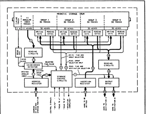
Functional Description of System.—The functional block diagram of a
magnetic drum storage system is shown in Figure 1. The dotted boundary surrounds those units which would be considered part of the storage section
of an IPS. The channels by which the storage section communicates with
other sections of the IPS are shown along the lower edge of the boundary. The external functions of the storage section are simple. If a word is to
be written into storage, the information which must be transmitted to the
storage section consists of: (1) the address of the desired storage position; (2) the word to be written; and (3) a control signal specifying that the
opera-tion is to "write." If the word occupying a given storage position is to be
read, the required information consists of: (1) the address of the desired
position; and (2) a control signal specifying that the word at that position is
to be "read" to one of several possible destinations (buses to two destinations
are shown).
The units with which the storage section communicates are determined
by the nature of the IPS. In a computer, for example, the address and the
control signals originate in the central program control of the computer. The
word to be written may come from the arithmetic section. The destinations
for words read out of storage may be the program control section, the
arithmetic section, or a printing device.
The storage section communicates internally and externally on a parallel
channel basis, in that the several binary digits of a word are transmitted at
one time over as many electrical channels. Heavy lines in Figure 1 represent
multi-channel buses for the transmission of words or addresses. Light lines
represent single or multiple channels for control information. In each external
channel, the presence of a pulse indicates a 1 and the absence of a pulse, a 0.
The channels within the storage section carry more specialized forms of
signals, such as d-c potentials, for example.
The word to be written and the address of the desired storage position
are held, until completion of the operation, in the Insertion Register and
the Address Register, respectively. These registers consist of toggle-circuits,
or static flip-flops. A toggle-circuit is an electron tube circuit having two
symmetrical stable states so that it is capable of holding a single binary digit
of information.
Upon completion of the specified writing or reading operation, a control
signal announcing completion is sent out by the storage section. At the same
time, the Address and Insertion Registers are cleared, so that the storage
section is then receptive to further assignment.
In the interest of clarity, the operation of the system will be described in
terms of an example having a specific set of storage characteristics: (1) word
size, b: 30 binary digits; (2) capacity in words, W: 8192 or 213; and (3)
maxi-mum access time, T: 16 milliseconds. The number of words which can be
stored in each group of 30 tracks is equal to RT, or 2048 (128 times 16).
Four track groups must therefore be provided, plus several additional tracks
for location and timing purposes. These are indicated in Figure 1.
The 8192 storage positions are designated by 8192 addresses. While the
set which consists of all the 13-digit binary numbers is the least redundant
and most economical of equipment.
The 13-digit address is composed of two parts, a 2-digit "group index"
and an 11-digit "angular index." The group index specifies one of the four, or 22, groups of tracks. The angular index specifies one of 2048, or 2U, angular positions of the drum.
In addition to the 120 storage tracks, there are 11 angular index tracks
and one timing track. These tracks contain permanently recorded
informa-tion. The angular index tracks contain the 2048 11-digit angular indices. The timing track serves as a source of timing pulses, for precisely marking the instant at which the drum passes through each of its 2048 discrete angu-lar positions. One of these timing pulses, selected on the basis of the desired angular index, denotes the instant at which the desired storage position is available for reading or writing.
Time-selection is performed by an 11-fold coincidence detector which
continuously compares the desired 11-digit angular index in the Address
Register with the outputs of the circuits which read the angular index
tracks. As long as the scanned angular indices do not match the desired
angular index, timing pulses cannot get through the coincidence detector.
When the drum passes through the angular position at which a match occurs, a single time pulse is delivered to the storage control circuits for triggering
of the appropriate writing or reading operation.
The function of the Writing Circuits is to replace the word at the specified storage position with the word standing in the Insertion Register. There is a
Writing Circuit associated with each of the 120 storage track magnetic
heads. A Writing Circuit contains two miniature thyratrons, each of which
can discharge a simple network through a winding on the magneto head.
The 30 pairs of thyratrons in the selected group are simultaneously triggered
by a pulse from the storage control circuits, but only one thyratron in each
pair fires, one to write a 1, the other to write a 0. One of tir thyratrons is
prevented from firing by application of a negative bias to its shield grid.
The choice of 1 or 0 is determined by the value of the corresponding digit in
the Insertion Register.
It should be noted that there is no need for "erasure," as such, since the
operation of writing a word into a storage position substitutes the new word
for the previous contents of that position. The word stored at a given position is simply the one that was written there last.
The use of thyratrons instead of "hard" vacuum tubes in the Writing
Circuits effects a significant saving in the number of tubes. The time which
must elapse between successive writing operations is admittedly longer for
thyratrons. However, the duty-cycle required of the writing operation is
generally so low that this limitation is of little consequence.
The reading operation consists in transmitting to the specified destination
the word stored at the position specified by the address in the Address
Register. The units which participate in reading are indicated in Figure 1
as Reading Gates, Reading Circuits, and Output Gates.
Track group selection is accomplished in the Reading Gates. These are
preamplifiers which are either blocked or operative, as determined by control voltages. Each of the 120 Reading Gates receives signals from its associated
36
AUTOMATIC COMPUTING MACHINERYmagnetic head, but only the selected group of gates transmits signals to the
Reading Circuits.
The Reading Circuits are 30 in number and consist of amplifiers and
wave-form shaping circuits. These operate continuously on the signals
originating in the selected group of tracks.
The amplified signals from the Reading Circuits are impressed on two
sets of Output Gates, one for each destination. At the instant denoted by
the selected time pulse, the appropriate set of Output Gates is pulsed. This
operation, by sampling the signal stream from the Reading Circuits at the
correct time, transmits the desired word to the specified destination.
The Storage Control Circuits consist of electronic switching and gating
circuits for translating the group index code, the selected time pulse, and
the external control signals into the appropriate group, time, and destination
signals. The Storage Control Circuits also include automatic lockout delays
which prevent a storage reference operation from following a previous one
too closely to permit complete circuit recovery. These delays are of the
order of 50 microseconds, except in the special case of a writing operation
which follows a previous writing operation. In this case, the second writing
operation must not take place until about 2 milliseconds after the first. If a storage reference operation is initiated too soon after a previous one and the desired angular index comes up before the lockout delays have cleared, the effect is simply to delay execution of the operation for one drum revolution.
TABLE I
Characteristics of 36 Magnetic Drum Storage Systems
DRUM DIMENSIONS. INCHES WORD SIÏE. b = 15 BINARY DIGITS WORD SIZE, b * 30 BINARY OIGITS ftOQP SIZE. ; 60 BINARY ¿HGITS 61,440 122.880 245.760 500 690 1080 2.048 4.096 8.192 1 .024 2.048 4.096 910 1090 1460 122.680 •245.760 491.520 8.192 16.384 32.768 510 700 109 0 4.096 •8.192 16.384 640 ■830 1210 2.048 4,096 920 1110 1480 4.5 3.0 245.760 491 .520 983.040 16.384 32.768 65.536 520 710 1100 930 1 120 1490 491,520 983.040 .966.080 32.768 65.536 31.072 530 720 1110 16.3b4 32.766 65.536 660 850 1240 16.384 32.768 940 1130 1500
The timing pulses in the storage section need not be synchronized with
the clock or timing pulses in other portions of the IPS, since all digital and
control information transmitted to the storage section is received and
tem-porarily held in toggle-circuits. Information transmitted from the storage
section is received on a toggle-circuit or relay register at the destination,
which provides similar buffer storage. The property of asynchronism obviates
the need for precise control of the angular velocity of the drum.
Characteristics of Typical Systems.—The principal characteristics of 36
similar to the one shown in the block diagram of Figure 1, with varia-tions in access time, storage capacity, and word size. All designs are based on a common set of physical parameters: 128 digital cells scanned by each head per millisecond; 80 digital cells per inch of track; and 8 tracks per axial inch of drum.
Each of the 12 horizontal lines of the table corresponds to a drum of given diameter and length. Four values of diameter and three values of length are
represented. The four diameters correspond to drum rotation periods or
maximum access times of 8, 16, 32, and 64 milliseconds. The three lengths
are for drums having 60, 120, and 240 storage tracks (in addition to angular
index and timing tracks). Each line of the table contains characteristics of
three systems corresponding to word sizes of 15, 30, and 60 binary digits.
Characteristics of the particular example described in connection with
Figure 1 are identified in the table by asterisks.
r
MAGNETIC STORAGE DRUM■~i
" ANGCH.A« Ï3 I INOEK ***• I TRACKS | I Hj H HEADS | 30 HEADS
51 WRIT1M
CKT5 SELECTED TIME PIA9E WOUP SELECTION^o*\
1/a\ A Re*D: TIME »NO
<y¿ \¿) DESTINATION SELECT.
K&-
~nh
I-fí,-1-1-A-©—®-'
9 9 a e? es
Fig. 1. Functional Block Diagram of Magnetic Drum Storage System.
The table contains information as to the number of magnetic heads and
the number of electron tubes required for each example. It will be noted
that the number of tubes is essentially constant for a given word size and
drum length. Under these conditions the access time and storage capacity
are both directly proportional to drum diameter.
Circuit cost per unit storage capacity may be expressed in terms of the
number of tubes per thousand binary digits. This quantity is seen to be a
decreasing function of access time and storage capacity, each considered
38
automatic
computing machinery
An idea of the space occupied by a given storage system may be gained from the tabulated data. The size of each drum is given in the table. The
size of the cabinets needed to contain the electronic circuits may be esti-mated by allowing about one cubic foot for every 30 tubes.
Loading of Drum.—The contents of storage undergo numerous changes
during the course of operation of an IPS. The entering of initial contents
and the introduction of new data at occasional intervals is a function of the
input section of the IPS. The choice of the input medium is governed largely
by the application. Input data may be on magnetic tape or wire, punched
cards, punched paper tape, or perhaps even introduced manually from a
keyboard. The present storage system is capable of accepting successive
items at rates up to about 500 words per second.
An input system using punched paper tape as the medium has been de-veloped for use with a storage system similar to the example of Figure 1.
The tape is scanned by a photoelectric reading device at a nominal speed
of 75 feet per minute, corresponding to a storage insertion rate of 1800 30-digit words per minute. Even if it should be desired to load the entire
drum, it would take only about five minutes to fill the 8192 storage positions.
The magnetic drum rotates continuously at its normal speed during the
loading operation. The tape feed need not be synchronized with drum
rota-tion. Simple means are provided for loading sequences of data into any
desired storage positions, in any order.
Some Possible Variations.—The described function table type of
mag-netic drum storage system embodies only the simplest and most
straight-forward features. Departures from these properties may be desirable to suit
the needs of certain applications.
For example, it is possible to shorten the access time in a system of given
capacity by assigning two or more magnetic heads to each track in place
of one. Another way to shorten access time, but at the expense of storage
capacity, is to repeat the stored information in several equal sectors about
the drum. This method is useful only if reading is a more frequent operation
than writing.
It is possible to add considerable flexibility to the manner in which stored
items are located for reading out. If suitable coincidence detectors are
pro-vided, items written into storage in the standard way may subsequently be
located on the basis of certain sets of digits within the stored words.
Although communication within the storage section is on a
parallel-channel basis, the described system may readily be made part of an IPS
operating serially, i.e., one in which the several digits of a word are
trans-mitted sequentially over a single channel. This requires that the Address
Register and the Insertion Register be endowed with the property of
shift-ing. The incoming word then arrives digit by digit at one end of the receiving
register. The register shifts its contents by one place upon arrival of each
digit, until the complete word is assembled. Shifting registers must also be
provided for transmitting words out of the storage section in serial fashion.
Status.—-The developmental status of the magnetic drum storage
tech-nique at the time of this writing (May 1949) may be summarized as follows.
A complete pilot model of the described function table type of system is undergoing final tests. Although this model is scaled down in capacity and
every basic system function is included. Tests of every operating function
under every expected condition have been performed with a repeated
relia-bility which confirms the adequacy of the selected design standards. Relia-bility of the basic circuits and of the magnetic and mechanical components has been further established in an extensive laboratory program of
com-ponent research and in the development of other types of magnetic drum
storage systems during the past two years.
Arnold
A. Cohen
Engineering Research Associates, Inc.St. Paul 4, Minnesota
Discussions
Notes on Modern Numerical Analysis—I
Editorial Note: There is a general feeling that, once the problems of
construction and maintenance of automatic digital computing machines are
solved, the remaining problems will be relatively simple. This may be the
case if attention is confined to standard classical problems; however, if an
attempt is made to use these machines fully, one is likely to encounter
formidable mathematical difficulties. It is expected that these difficulties
will be discussed in the current mathematical journals; but there are also
smaller, more technical problems which may cause trouble. It is believed that a discussion of these smaller problems will prove beneficial in avoiding a great many difficulties which are expected to arise when the machines are in actual operation ; and we should like to urge interested persons to submit
technical notes of this nature for future publication in the Automatic Com-puting Machinery Section of MTAC. These notes could be by-products of
or preliminaries to more constructive investigations. It would be a great
advantage, for expository purposes, if the authors, even at the expense of
a choice of an extravagant example, could exhibit the troubles under
discussion on a manual scale.
Solution of Differential Equations by Recurrence Relations
1.1. In general the most satisfactory method for the numerical solution
of ordinary differential equations is one of the "extrapolation" methods.1
These methods have proven very efficient in the hands of a practiced
com-puter. There is little doubt that some of the experience he uses could be
codified and adapted for use on automatic digital computing machines.
Nevertheless, the use of some direct recursive process is very attractive and
worth investigation.
Let us consider the solution by such methods of the equation
(1)
y" = - y,
with the boundary conditions y(0) = 0, y'(0) = 1, by use of the well-known
formula2
(2) h2y" = (S2 - tV54 + TfVS6-)y.
1.2. First let A = 1, using only the first term on the right-hand side of (2). If the condition y'(0) = 1 is replaced by y(l) = 1 the following recurrence
relation is obtained