With new high rigidity
linear guide
Allowable moment improvement
illustrated below
∗
Yaw moment Roll moment 0 0.5 1 1.5 Pitch moment Allowable moment (N·m)2.4
times greaterThe weight has been reduced by incorporating
a new high rigidity linear guide and piston.
(ø20-10 stroke)
19
% reduced
W
eight
Mp F My F F Mr2.1
times greater1.7
times greater Existing model Existing model New New New New New New MXH MXH MXH Existing modelAllowable moment
Improved
by up to
240
%
∗ Allowable moment caused by static load
(The above graph is a comparison between the new MXH and the existing MXH6.)
New NewMXH Existing model
369
g
455
g
Compact Slide
ø
6,
ø
10,
ø
16,
ø
20
Series
MXH
New
New
RoHS
High allowable moment
High rigidity achieved with new
circulating type
linear guide
High rigidity achieved with new
circulating type
linear guide
High rigidity achieved with
new
circulating type
linear guide
Workpiece
Pitch moment
Action
Useful when long stroke/travel isrequired
Series Variations
Model Made to Order
MXH6
MXH10
Standard stroke (mm)
5 10 15 20 25 30 40 50 60
Mounting is possible in 4 directions.
Lateral mounting (Body through-hole)
Lateral mounting (Body thread)
Vertical mounting (Body thread) Vertical mounting (Body thread)
Application
Example
Bore size (mm) MXH MXH existing model
6 10 16 20 0.81 1.69 3.49 5.86 0.47 0.96 1.88 3.14 New New
Pitch Moment
(N·m)Traveling parallelism is the same
as the existing model.
Deflection at the extended position of the table is the same as the existing model.
Traveling parallelism Stroke (mm) 5 to 30 0.05 mm or less 40 to 60 0.1 mm or less
Bore size (mm) MXH MXH existing model
6 10 16 20 0.81 1.69 3.49 5.86 0.39 0.82 1.59 2.75 New New
Yaw Moment
(N·m)Bore size (mm) MXH MXH existing model
6 10 16 20 1.4 3.19 6.47 11.66 0.59 1.37 2.75 5.49 New New
Roll Moment
(N·m)Piping is possible in 3 directions.
Mounting is completely interchangeable with existing model.
Dimensions including workpiece mounting dimensions and cylinder mounting dimensions are the same as the existing model.
Small auto
switches capable
(D-M9
, D-A9
)
MXH
New NewIf changing the port location, “Made to Order” model (-XC3) is available.
-XC79: Machining tapped hole, drilled hole and pin hole additionally -XB13: Low speed cylinder (5 to 50 mm/s) -XC3
∗ Selection of a bore size cannot be made only with above allowable moment. Select a bore size in accordance with “Model Selection” on pages 2 and 3.
OUT
IN OUT port
OUT port (On both sides)
Mounting orientation Vertical Horizontal Maximum speed (mm/s) Load eccentricity L1 (mm) Selection graph
∗ L: Overhang (the distance from the cylinder shaft center to the load center of gravity) The direction of L can also be a diagonal direction. (Refer to the drawing at right.)
∗ H:Distance from the cylinder center axis to the mounting surface for the table
Selection Graph
z
to
c
(Vertical Mounting)
Selection Conditions
: Follow the tables below in order to determine selection conditions and choose one selection graph.Caution
Confirmation of theoretical output is required separately. Refer to “Theoretical Output” on page 5.10 1 0.1 0.01 ø20 ø16 ø10 ø6 ø20 ø16 ø10 ø6 Mass m (kg) Mass m (kg) 0 0 1 0.1 0.01 20 20 40 40 Overhang L (mm) Overhang L (mm) 60 60 80 80 100 100 Up to 100 z 200 ⁄2 Up to 300 100 , 200 . Up to 500 100 ⁄1 50 ⁄0 Up to 100 100 b 50 v 200 n 50 m Up to 300 — x Up to 500 c
Graph xx Maximum Speed 300 mm/s or Less
Graph cc Maximum Speed 500 mm/s or Less Graph zz Maximum Speed 100 mm/s or Less
ø20 ø16 ø10 ø6 0.1 1 10 100 0 20 40 60 80 100 Overhang L (mm) Mass m (kg)
Series
MXH
Model Selection
Selection Example (Vertical Mounting)
1. Selection conditions Mounting: Vertical
Maximum speed: 500 mm/s Overhang L: 40 mm Load mass m: 0.1 kg
Refer to Graph
c
based on vertical mounting and a speed
of 500 mm/s.
In Graph
c
, find the intersection of a 40 mm overhang
L
and load mass
m
of 0.1 kg, which results in a determination
of ø16.
m LH m L1: Load eccentricity L LCylinder shaft center
m Load center of gravity H H dimension (mm) MXH6 24.5 MXH10 30.5 MXH16 34.5 MXH20 41.5
Selection Graph
v
to
⁄2
(Horizontal Mounting)
Maximum Speed 100 mm/s or Less
Maximum Speed 300 mm/s or Less
Maximum Speed 500 mm/s or Less
Selection Example (Horizontal Mounting)
2. Selection conditions Mounting: Horizontal Maximum speed: 500 mm/s Load eccentricity L1: 50 mm
Overhang L: 30 mm Load mass m: 0.1 kg
Refer to Graph
⁄0
based on horizontal mounting, a speed of 500 mm/s and load eccentricity
L
1of 50 mm.
Mass m (kg) Mass m (kg)
Mass m (kg)
Mass m (kg) Mass m (kg) Mass m (kg)
Mass m (kg)
Mass m (kg)
Mass m (kg)
Overhang L (mm) Overhang L (mm) Overhang L (mm)
Overhang L (mm)
Overhang L (mm) Overhang L (mm) Overhang L (mm)
Overhang L (mm) Overhang L (mm) ø20 ø16 ø10 ø6 ø20 ø16 ø10 ø6 ø20 ø16 ø10 ø6 ø20 ø16 ø10 ø6 ø20 ø16 ø10 ø6 ø20 ø16 ø10 ø6 ø20 ø16 ø10 ø6 ø20 ø16 ø10 ø6 ø20 ø16 ø10 ø6
Graph ⁄⁄22 Load Eccentricity 200 mm Graph .. Load Eccentricity 200 mm
Graph nn Load Eccentricity 200 mm
Graph bb Load Eccentricity 100 mm Graph ,, Load Eccentricity 100 mm Graph ⁄⁄11 Load Eccentricity 100 mm Graph ⁄⁄00 Load Eccentricity 50 mm Graph mm Load Eccentricity 50 mm
Graph vv Load Eccentricity 50 mm
0.01 0.1 1 0 20 40 60 80 100 0.01 0.1 1 10 0 20 40 60 80 100 0.1 1 10 100 0 20 40 60 80 100 0.1 1 10 0 20 40 60 80 100 0.1 1 10 0 20 40 60 80 100 0.01 0.1 1 10 0 20 40 60 80 100 0.01 0.1 1 10 0 20 40 60 80 100 0.01 0.1 1 0 20 40 60 80 100 0.01 0.1 1 0 20 40 60 80 100
Series
MXH
Nil
S 2 pcs.1 pc.
Bore size
Number of auto switches
Cylinder stroke (mm)
MXH
Auto switch
Without auto switch (Built-in magnet) Nil
Refer to “Standard Stroke” on the next page.
∗ For applicable auto switch model, refer to the table below.
Compact Slide
6 10 16 20 6 mm 10 mm 16 mm 20 mm60
∗ Lead wire length symbols: 0.5 m ···Nil (Example) M9NW 1 m ··· M (Example) M9NWM 3 m ···L (Example) M9NWL 5 m ···Z (Example) M9NWZ
∗ Refer to page 13 for applicable auto switches other than listed above.
∗ For details about auto switches with pre-wired connector, refer to the WEB catalog or the Best Pneumatics No.3 catalog.
∗ Auto switches are shipped together, (but not assembled).
A96V A93V A90V M9NV M9PV M9BV M9NWV M9PWV M9BWV M9NAV∗∗ M9PAV∗∗ M9BAV∗∗ A96 A93 A90 M9N M9P M9B M9NW M9PW M9BW M9NA∗∗ M9PA∗∗ M9BA∗∗ Type Special function
3-wire (NPN equivalent) — 24 V Grommet 24 V 2-wire 3-wire (NPN) 3-wire (PNP) 2-wire 3-wire (NPN) 3-wire (PNP) 2-wire 3-wire (NPN) 3-wire (PNP) 2-wire Yes No Yes Electrical entry Load voltage Wiring
(Output) DC AC connector Applicable loadPre-wired Auto switch model Lead wire length (m)
Perpendicular In-line (Nil)0.5 (Z)5
Indicator light
Reed
auto switch
Solid state auto switch
Grommet — 100 V 100 V or less — — — — — — 1 (M) — — — IC circuit — IC circuit IC circuit — IC circuit — IC circuit — — Relay, PLC Relay, PLC — — Diagnostic indication (2-color indication) Water resistant (2-color indication) 5 V 12 V 12 V 12 V 12 V 5 V, 12 V 5 V, 12 V 5 V, 12 V 3 (L)
Applicable Auto Switches
/Refer to the WEB catalog or the Best Pneumatics No.3 catalog for further information on auto switches.10
M9BW
∗∗ Water resistant type auto switches can be mounted on the above models, but in such case SMC cannot guarantee water resistance. Please consult with SMC regarding water resistant type with the above model numbers.
Compact Slide
ø
6,
ø
10,
ø
16,
ø
20
Series
MXH
How to Order
Z
Made to Order
∗ Refer to page 5 for details.
RoHS
∗ Solid state auto switches marked with “” are produced upon receipt of order.
Standard Stroke
Bore size (mm) 6, 10, 16, 20 5, 10, 15, 20, 25, 30, 40, 50, 60 0.3 0.5 0.7 (N) Standard stroke (mm)Theoretical Output
Bore size (mm) Operating direction OUT IN OUT IN OUT IN OUT IN 28 21 78 66 201 172 314 264 8 6 23 19 60 51 94 79 14 10 39 33 101 86 157 132 19 14 55 46 141 121 220 185 Piston area (mm2)Operating pressure (MPa)
3 4 6 8 Rod size (mm)
Specifications
Fluid ActionPiping port size
Minimum operating pressure Maximum operating pressure Proof pressure
Ambient and fluid temperature Piston speed
Allowable kinetic energy (J) Lubrication
Cushion
Stroke length tolerance
Air Double acting
M5 x 0.8
Non-lube
Rubber bumper on both ends
Solid state auto switch D-M9, M9W Reed auto switch D-A9
+1.0 0
0.7 MPa 1.05 MPa
0.0125 0.025 0.05 0.1
0.15 MPa 0.06 MPa 0.05 MPa
Without auto switch: −10 to 70°C
With auto switch: −10 to 60°C (No freezing) 50 to 500 mm/s 6 10 16 20 Auto switch (Option) 6 10 16 20
Weight
5 10 15 20 25 30 40 50 60 Stroke (mm) Model MXH6 MXH10 MXH16 MXH20 (g) Low speed cylinder (5 to 50 mm/s)Special port location
Intermediate stroke (Spacer type) Fluororubber seal
Machining tapped hole, drilled hole and pin hole additionally Symbol Specifications -XB13 -XC3 -XC19 -XC22 -XC79
Note) Intermediate strokes are available with “Made to Order” model (-XC19). (For details, refer to page 18.)
Made to Order
(Refer to pages 16 to 18 for details.) Symbol Rubber bumper 61 104 194 352 66 112 204 369 75 125 222 400 80 133 232 417 88 146 250 448 93 153 260 466 107 174 288 514 120 195 316 562 134 216 343 610 Bore size (mm)
Series
MXH
Table Displacement
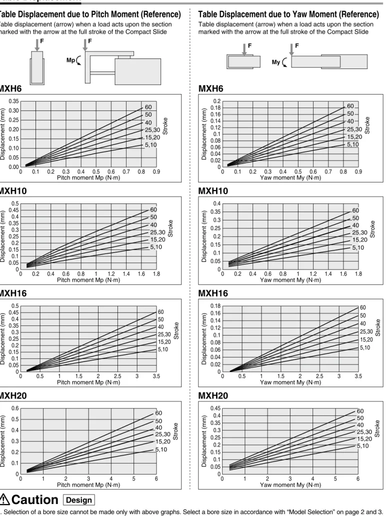
Table Displacement due to Pitch Moment (Reference)
Table displacement (arrow) when a load acts upon the section marked with the arrow at the full stroke of the Compact Slide
Table Displacement due to Yaw Moment (Reference)
Table displacement (arrow) when a load acts upon the section marked with the arrow at the full stroke of the Compact Slide
1. Selection of a bore size cannot be made only with above graphs. Select a bore size in accordance with “Model Selection” on page 2 and 3. 2. Displacement may increase after an impact load has been applied. When the table is subjected to an impact load, there may be
permanent distortion of the guide unit and increased displacement.
MXH6
MXH6
MXH10
MXH10
MXH16
MXH20
Displacement (mm) Pitch moment Mp (N·m) Pitch moment Mp (N·m) Pitch moment Mp (N·m) Pitch moment Mp (N·m) Yaw moment My (N·m) 60 50 40 15,20 5,10 25,30 60 50 40 15,20 5,10 25,30 Displacement (mm) Yaw moment My (N·m) Displacement (mm) Displacement (mm) Displacement (mm) Displacement (mm) Yaw moment My (N·m) Displacement (mm) Yaw moment My (N·m) Displacement (mm)MXH16
MXH20
Design
Caution
0.00 0.05 0.10 0.15 0.20 0.25 0.30 0.35 0 0.1 0.2 0.3 0.4 0.5 0.6 0.7 0.8 0.9 0 0.02 0.04 0.06 0.080.1 0.12 0.14 0.16 0.180.2 0 0.1 0.2 0.3 0.4 0.5 0.6 0.7 0.8 0.9 0 0.050.1 0.150.2 0.250.3 0.350.4 0.450.5 0 0.2 0.4 0.6 0.8 1 1.2 1.4 1.6 1.8 0 0.050.1 0.150.2 0.250.3 0.350.4 0.450.5 0 0.5 1 1.5 2 2.5 3 3.5 0 0.1 0.2 0.3 0.4 0.5 0.6 0 1 2 3 4 5 6 0 0.05 0.1 0.15 0.2 0.25 0.3 0.35 0.4 0 0.2 0.4 0.6 0.8 1 1.2 1.4 1.6 1.8 0 0.02 0.04 0.06 0.08 0.1 0.12 0.14 0.16 0.18 0 0.5 1 1.5 2 2.5 3 3.5 0 0.05 0.1 0.15 0.2 0.250.3 0.35 0.4 0.45 0 1 2 3 4 5 6 Stroke Stroke Stroke Stroke Stroke Stroke Stroke Stroke 60 50 40 15,20 5,10 25,30 60 50 40 15,20 25,30 60 50 40 15,20 5,10 25,30 60 50 40 15,20 5,10 25,30 60 50 40 15,20 5,10 25,30 60 50 40 15,20 5,10 25,30 5,10 Mp F F F F MyTable Accuracy
Allowable Moment
Traveling parallelism Model MXH6 MXH10 MXH16 MXH20 Allowable moment (N·m) Stroke (mm) Pitch moment Mp 0.81 1.69 3.49 5.86 Yaw moment My 0.81 1.69 3.49 5.86 Roll moment Mr 1.40 3.19 6.47 11.66 5 to 30 0.05 mm or less 40 to 60 0.1 mm or lessTable Displacement due to Roll Moment (Reference)
Table displacement (at A) when a load acts upon section F at the full stroke of the Compact Slide
MXH10
MXH20
Displacement (mm) Displacement (mm) Displacement (mm) Displacement (mm) Roll moment Mr (N·m) Roll moment Mr (N·m) Roll moment Mr (N·m) Roll moment Mr (N·m)MXH6
MXH16
Table Displacement
0 0.005 0.01 0.015 0.02 0.025 0.03 0.035 0.04 0 0.2 0.4 0.6 0.8 1 1.2 1.4 0 0.0050.01 0.0150.02 0.0250.03 0.0350.04 0.0450.05 0 0.5 1 1.5 2 2.5 3 3.5 0 0.01 0.02 0.03 0.04 0.05 0.06 0.07 0.08 0.090.1 0 1 2 3 4 5 6 7 0 0.02 0.04 0.06 0.080.1 0.12 0.14 0.16 0.18 0 2 4 6 8 10 12Design
Selection of a bore size cannot be made only with
above allowable moment. Select a bore size in
accor-dance with “Model Selection” on pages 2 and 3.
Caution
A F
Mr A
Construction
No. Cylinder tube Rod cover Piston rod Guide Table Piston Magnet Steel ball Bumper Bumper Countersunk head screw Nut Rod seal Piston seal Gasket Plug Description Material Aluminum alloy Aluminum alloy Stainless steelThe main parts are made of stainless steel. Aluminum alloy Aluminum alloy Magnetic material Carbon steel Urethane Urethane Carbon steel Brass NBR NBR NBR Carbon steel Note Hard anodized Hard anodized Hard anodized Chromated Nickel plating Nickel plating Zinc chromated
Component Parts
1 2 3 4 5 6 7 8 9 10 11 12 13 14 15 16Note) The MXH series cannot be disassembled.
!2
t
!3
!1
y u
!4
i
!0
e
o
!6
w q !5 r
Dimensions:
ø
6
Stroke (mm) 5 10 15 20 25 30 40 50 60 J 4 4 4 4 4 4 6 6 6 LA 10 10 20 20 30 30 20 25 30 LB — — — — — — 20 25 30 LT 42 42 52 52 62 62 72 82 92 NS 14 14 24 24 30 30 45 55 60 LT 9 15 LA LB 8 J x M3 x 0.5 Depth 5 4 x M3 x 0.5 Depth 4.8 2 x M5 x 0.8 Cylinder port 19 5 10.5 18 5.5Note 1) Refer to “Specific Product Precautions” for mounting of the Compact Slide and a workpiece. Note 2) When changing the port location, please order a new port plug: MXH-P (2 pcs.)
4 x M3 x 0.5 Depth 5.5 17 15 38 39 16 9 5.5 8.5 4 NS 31 + Stroke 39.5 + Stroke 10 18 5.5 5 19 5 3 x M4 x 0.7 through Pilot hole dia ø3.3
6 x ø6 counterbore depth 3.3 Plug for port: MXH-P (4 pcs.)
10
10 5 + Stroke 4 x M3 x 0.5 Depth 4.8
Dimensions:
ø
10
Stroke (mm) 5 10 15 20 25 30 40 50 60 J 4 4 4 4 4 4 6 6 6 LA 10 10 20 20 30 30 20 25 30 LB — — — — — — 20 25 30 LT 49 49 59 59 69 69 79 89 99 NS 14 14 24 24 30 30 45 55 60 4 x M4 x 0.7 Depth 6 2 x M5 x 0.8 Cylinder port 23 5 20 6.5 13 LT 19 11 11 LA LB J x M4 x 0.7 Depth 6Note 1) Refer to “Specific Product Precautions” for mounting of the Compact Slide and a workpiece. Note 2) When changing the port location, please order a new port plug: MXH-P (2 pcs.)
11 20 4 x M4 x 0.7 Depth 7.5 21.5 18 46 47 13 12 5 + Stroke 4 x M4 x 0.7Depth 6 23 6 5 7.5 11.5 5 NS 35 + Stroke 46.5 + Stroke 12.5 20 6.5 3 x M5 x 0.8 through Pilot hole dia ø4.3 6 x ø7.5 counterbore depth 4.4
Plug for port: MXH-P (4 pcs.)
Dimensions:
ø
16
Stroke (mm) 5 10 15 20 25 30 40 50 60 J 4 4 4 4 4 4 6 6 6 LA 10 10 20 20 30 30 20 25 30 LB — — — — — — 20 25 30 LT 58 58 68 68 78 78 88 98 108 NS 20 20 30 30 40 40 50 60 60 16 24 LT 14 LA LB J x M4 x 0.7 Depth 6 4 x M4 x 0.7 Depth 6 2 x M5 x 0.8 Cylinder port 27 25 17 5.5 6.5Note 1) Refer to “Specific Product Precautions” for mounting of the Compact Slide and a workpiece. Note 2) When changing the port location, please order a new port plug: MXH-P (2 pcs.)
16 25 21.5 26 52.5 53.5 3 x M5 x 0.8 through Pilot hole dia ø4.3 6 x ø7.5 counterbore depth 4.4
Plug for port: MXH-P (4 pcs.)
6 27 5.5 10 14 12.5 25 5 NS 42 + Stroke 56 + Stroke 6.5 17 12 10 + Stroke 4 x M4 x 0.7 Depth 6 4 x M4 x 0.7 Depth 10
Series
MXH
Dimensions:
ø
20
Stroke (mm) 5 10 15 20 25 30 40 50 60 J 4 4 4 4 4 4 6 6 6 LA 10 10 20 20 30 30 20 25 30 LB — — — — — — 20 25 30 LT 64 64 74 74 84 84 94 104 114 NS 20 20 25 25 40 40 50 70 70 4 x M5 x 0.8 Depth 8 2 x M5 x 0.8 Cylinder port 34 6 32 7 20 LT 20 31 14 LA LB J x M5 x 0.8 Depth 6.5Note 1) Refer to “Specific Product Precautions” for mounting of the Compact Slide and a workpiece. Note 2) When changing the port location, please order a new port plug: MXH-P (2 pcs.)
32 20 24.5 34 63.5 64.5 3 x M6 x 1.0 through Pilot hole dia ø5.1
6 x ø9.3 counterbore depth 8 Plug for port: MXH-P (4 pcs.)
6.5 34 6 32 7 11 15.5 6 NS 52.5 + Stroke 68 + Stroke 15 4 x M5 x 0.8 Depth 8 10 + Stroke 15 20 4 x M5 x 0.8 Depth 11
Auto Switch Proper Mounting Position (Detection at Stroke End) and Its Mounting Height
[ ]: Value of the D-M9A ( ): Value of the D-A90/A93
Bore size (mm) 6 10 16 20 A 12.5 11.0 18.0 26.0 W 3.5 (6) –2.0 (0.5) –2.0 (0.5) –4.5 (–2) B — 3.5 4.0 6.5 D-A9, D-A9V D-M9W, D-M9 D-M9WV, D-M9V A 16.5 15.0 22.0 30.0 A 16.5 15.0 22.0 30.0 W 7.5 2.0 2.0 –0.5 W 5.5 0 0 –2.5 B 2.5 7.5 8.0 10.5 B 2.5 7.5 8.0 10.5 D-M9A A 16.5 15.0 22.0 30.0 W 9.5 4.0 4.0 1.5 B 2.5 7.5 8.0 10.5 D-M9AV A 16.5 15.0 22.0 30.0 W 7.5 2.0 2.0 –0.5 B 2.5 7.5 8.0 10.5
D-M9
D-M9
W
D-M9
A
D-A9
D-M9
V
D-M9
WV
D-M9
AV
D-A9
V
(mm)Auto switch model Bore size
6 10 16 20
( ): Value of the D-M9AV/A9V
Operating Range
(mm)D-A9, A9V
Note 1) Negative figures in the table W indicate that an auto switch is mounted inward from the edge of the cylinder body.
Note 2) In the case of models with 5 and 10 strokes, the auto switch may not turn off due to operating range or two auto switches may turn on simultaneously. Fix auto switches outside 1 to 4 mm further than the values in the table above. (If one auto switch is used, make sure that it turns ON and OFF properly; If two auto switches are used, make sure that both auto switches turn ON.) Note 3) ( ) in column W denotes the D-A90/A93 dimensions.
3 5 3.5 6 5 9 6 11
Minimum Stroke for Auto Switch Mounting
Applicable auto switch model
(mm) Number of auto switches
mounted 1 pc. 2 pcs. 5 10 5 5 5 10 D-A9, A9V D-M9, M9V D-M9D-M9W, M9A, M9WVAV
Other than the applicable auto switches listed in "How to Order", the following auto switches can be mounted.
D-M9, M9VD-M9W, M9WV D-M9A, M9AV
Series
MXH
Auto Switch Mounting
∗ Values which include hysteresis are for guideline purposes only, they are not a guarantee (assuming approximately ±30% dispersion) and may change substantially depending on the ambient environment.
W A B A W B 22 [24] (24.5) 20 (22)
Auto Switch Mounting
• When tightening the auto switch mounting screw, use a watchmaker’s screwdriver with a handle 5 to 6 mm in diameter.
Note) When used with side ported type, it is not possible to mount the D-A9V/M9V type on the side to which the piping is connected.
Tightening Torque of Auto Switch Mounting Screw
Auto switch model Tightening torque0.10 to 0.20 D-A9(V) (N·m) D-M9(V) D-M9W(V) D-M9A(V) 0.05 to 0.15 Watchmaker’s screwdriver
Auto switch mounting screw
Auto switch
Relay Relay Input COM COM Input COM Input COM Input
2-wire OR connection
2-wire AND connection
3-wire OR connection for PNP output
(Performed with auto switches only) (Using relays)
3-wire AND connection for PNP output
3-wire OR connection for NPN output
(Performed with auto switches only) (Using relays)
3-wire AND connection for NPN output
(PLC internal circuit) (PLC internal circuit) (PLC internal circuit) (PLC internal circuit)
2-wire
3-wire, PNP
2-wire
3-wire, NPN
Load Load Load Load Load Load Load Load Blue Black Brown Auto switch 2 Blue Black Brown Auto switch 1 Blue Black Brown Auto switch 2 Blue Black Brown Auto switch 1 Blue Black Brown Auto switch 2 Blue Black Brown Auto switch 1 Blue Black Brown Auto switch 2 Blue Black Brown Auto switch 1 Blue Brown Auto switch 2 Blue Brown Auto switch 1 Blue Black Brown Auto switch 2 Blue Black Brown Auto switch 1 Blue Brown Auto switch 2 Blue Brown Auto switch 1 Blue Black Brown Auto switch 2 Blue Black Brown Auto switch 1 Blue Brown Blue Brown Blue Black Brown Blue Black Brown Auto switch Auto switch Auto switch Auto switchExample of AND (Series) and OR (Parallel) Connection
Sink Input Specifications
Source Input Specifications
Prior to Use
Auto Switch Connection and Example
Load voltage at ON = Power supply voltage – Residual voltage x 2 pcs. = 24 V − 4 V x 2 pcs.
Load voltage at OFF = Leakage current x 2 pcs. x Load impedance
= 1 mA x 2 pcs. x 3 kΩ
(Solid state) (Reed) When two auto switches are
connected in series, a load may malfunction because the load voltage will decline when in the ON state. The indicator lights will light up when both of the auto switches are in the ON state.
Auto switches with load voltage less than 20V cannot be used.
When two auto switches are connected in parallel, malfunction may occur because the load voltage will increase when in the OFF state.
Because there is no current leakage, the load voltage will not increase when turned OFF. However, depending on the number of auto switches in the ON state, the indicator lights may sometimes grow dim or not light up, due to the dispersion and reduction of the current flowing to the auto switches. Connect according to the applicable PLC input specifications, as the connection method will vary depending on the PLC input specifications.
Series
MXH
Simple Specials
These changes are dealt with Simple Specials System.
Machining tapped hole, drilled hole and pin hole additionally
1
Series
Compact Slide MXH Standard type Table Type
Model Component parts applicablefor additional machining MXH
Applicable Series and Component Parts
Applicable for Additional Machining
Precautions
Tapped hole
Drilled hole
Pin hole
Hole dia. Tolerance 3 or less +0.01 0 Over 3 to 6 +0.012 0 +0.015 0 Over 6 to 10 +0.018 0 +0.021 0 Over 10 to 18 Over 18 to 20
Supplementary Explanation
/Holes which can be additionally machined are the following 3 types.Note) P stands for thread pitch.
Additional Machining Restriction
/Since the slant lines denote the additional machining restriction section, design the dimensions, referring to below.Model MXH6 MXH10 MXH16 MXH20 D1 11 14 18 22 D2 5.8 6 7.5 9.7 LY 9 11 16 22 LX 20 22 29 32 LZ 5.5 6.5 6.5 7
Dimensions of areas where additional machining is not allowed
Table material: Aluminum
(mm) This simple special is meant for machining additionally tapped hole, drilled hole and pin hole, as requested from users, on parts designed largely for mounting a workpiece etc., in the combined air cylinders. Note that there are some areas where additional machining is not allowed, so please refer to the additional machining restriction section below.
• We cannot take any responsibility as for the intensity of holes machined additionally and the effects of decreased intensity for the product itself.
• Areas where additional machining was done will not be plated again.
• Be sure to fill in “through” for through-hole, and “effective depth” for blind hole.
• When using by machining through-hole additionally, ensure that the tip of the bolt etc., for mounting a workpiece should not stick into the cylinder side. It may result in an unexpected problem.
• Use caution not to interfere the existing mounting hole on the standard products with the hole to be machined additionally. But it is possible to drill additionally the larger size of hole at the same position as the existing hole.
Designated nominal diameter and tapped hole of a pitch are machined additionally. (Maximum nominal thread diameter M20) Blind hole is deep into the bottom of prepared hole which sums up A to C in the figure below in contrast to the effec-tive depth of tapped hole. When there is a condition which does not allow through-hole etc., leave sufficient thickness in the inner part of hole.
Drilled hole of a designated internal diameter is machined.
(Maximum hole diameter 20 mm) If you wish for blind hole, instruct us with effective depth. (Refer to the figure below.) Besides, dimensional accuracy for internal diameter will be ±0.2 mm.
Pin hole of a designated diameter (reamer hole) is machined. (Maximum hole diameter 20 mm)
Internal dimension tolerates H7 tolerance to the designated hole diameter. (Refer to the table below.)
D1 LY LZ D2 LX D (Thread size)
A (Effective thread depth)
B = 3 x P
(Incomplete thread section) C = 0.3 x (D – P) D A (Effective depth) C = 0.3D DH7 A (Effective depth)
Symbol
-XC79
Series
MXH
Made to Order
Please contact SMC for detailed dimensions, specifications and lead times.
Low speed cylinder (5 to 50 mm/s)
1
-XB13
Symbol
Even if driving at lower speeds 5 to 50 mm/s, there would be no stick-slip phenomenon and it can run smoothly.
Special port location
2
Symbol
-XC3
Change to the standard port location
XB13
Low speed cylinder
Specifications
5 to 50 mm/s Same as standard type Same as standard type Piston speed
Additional specifications Dimensions
Note 1) Operate without lubrication from a pneumatic system lubricator.
Note 2) For speed adjustment, use speed controllers for controlling at lower speeds. (Series AS-FM/AS-M)
Operating Precautions
Warning
Be aware that smoking cigarettes etc., after your hands have come into contact with the grease used in this cylinder can create a gas that is hazardous to humans.
The port location of a standard product is in the axial direction, and it is shipped as plugged on both sides. However, side ported type can be ordered. A shifting of plugs is not required by users.
Standard model no.
XC3
Change of port location
Standard -XC3A -XC3B
MXH
How to Order
Standard model no.
MXH
How to Order
Relationship between Port Location and Plug Position
Specifications: Same as standard type
IN OUT Plug Plug OUT port IN port Plug IN port OUT port Plug IN port OUT port Plug Plug
Intermediate stroke (Spacer type)
3
-XC19
Symbol
Dealing with the intermediate stroke by installing a spacer with the standard stroke cylinder
Fluororubber seal
4
-XC22
Symbol
XC19
Intermediate stroke (Spacer type)
Applicable Stroke
ø6, ø10, ø16, ø20 35, 45, 55 (mm)
• Dealing with it by installing a 5 mm width spacer with the
standard stroke cylinder
• Please contact SMC when stroke other than applicable stroke is
required.
XC22
Fluororubber seal
Specifications
Fluororubber
Same as standard type Same as standard type
Seal material
Ambient temperature range Additional specifications Dimensions
Standard model no.
MXH
How to Order
Standard model no.
MXH
How to Order
Note 1) Please contact SMC, as the type of chemical and the operating temperature may not allow the use of this
product.
Note 2) Cylinders with auto switches can also be produced;
however, auto switch related parts (auto switch units, mounting brackets, built-in magnets) are the same as standard products.
Before using these, please contact SMC regarding their suitability for the operating environment.
Specifications: Same as standard type
Dimensions: External dimensions are the same as standard stroke products added by
5 mm for the required stroke.
Note) With auto switch: –10°C to 60°C
Without auto switch : –10°C to 70°C (No freezing)
1. When the Compact Slide with the D-A9 or D-M9 auto switch is used, the auto switches could activate unintentionally if the installed distance is less than the dimension shown in Table (1). Therefore, make sure to provide at least this much clearance. Due to unavoidable circumstances, if they must be used with less distance than the dimensions given in the table below, the cylinders must be shielded. Therefore, affix a steel plate or a magnetic shielding plate (MU-S025) to the area on the cylinder that corresponds to the adjacent auto switch. (Please contact SMC for details.) The auto switch could activate unintentionally if a shielding plate is not used.
Dimensions of a shielding plate (MU-S025) that is sold separately are indicated as reference.
Auto Switch Mounting
When installing in close proximity to each other
Caution
1. Do not place your fingers in the clearance between the non-rotating plate and the cylinder tube. Your fingers could get caught between the table and the cylinder tube when the piston rod retracts.
If fingers are caught in a cylinder, there is a danger of injury due to the strong cylinder output, and therefore, caution must be exercised. 2. In terms of the work load and moment, operate the cylinder
below the maximum work load and allowable moment.
3. If the output of the Compact Slide is applied directly to the table, make sure it is applied along the rod axial line. (Refer to the figure below.)
Caution
Operating Direction with Different Pressure Ports
1. The Compact Slide can be piped in 3 directions.Check the pressure port and the operating direction. (Refer to the figure below.)
Change the plug location depending on the application. Confirm that there is no air leakage after changing the plug location. If there is slight leakage, remove the plug, check the seat surface and reassemble.
Caution
Bore size (mm) MXH6 MXH10 MXH16 MXH20 d 5 5 10 15 L 21 25 35 47 Table (1) (mm)Series
MXH
Specific Product Precautions 1
18
36
Material: Ferrite stainless steel, Thickness: 0.3 mm Since the back side is treated with adhesive, it is possible to attach to the cylinder.
Be sure to read this before handling. Refer to the back cover for Safety Instructions,
“Handling Precautions for SMC Products” and the Operation Manual for Actuator and
Auto Switch Precautions. http://www.smcworld.com
IN
OUT OUT port
IN port IN port
(On both sides) OUT port (On both sides)
When changing the port location, please order the following plug. Replacement port plug part number: MXH-P (2 pcs.) L
d
Be aware that smoking cigarettes etc., after your hands have come into contact with the grease used in this cylinder can create a gas that is hazardous to humans.
Warning
Operating Precautions
Operating Precautions
4. Make sure to connect a speed controller and adjust it to a speed of 500 mm/s or less to operate the cylinder.
5. If the vibration of the workpiece due to cylinder operation is clearly noticeable, recheck the operating conditions. Even when the moment applied to the product is under the allowable moment, the vibration width may be increased if a large amount of eccentric load is applied.
Backlash in the Stroke Direction
• Since the connection between the piston rod and table is a
floating mechanism, the table has backlash of 0.15 mm or less in the stroke direction. (Refer to the figure below.)
Caution
Table
Piston rod
Mounting
Caution
1. When tightening threads for the Compact Slide, properly tighten within the specified torque.
How to Mount the Compact Slide
Lateral Mounting (Body through-hole)
Model MXH6 MXH10 MXH16 MXH20 Bolt M3 x 0.5 M4 x 0.7 M4 x 0.7 M5 x 0.8 L1 12.7 15.6 20.6 24.0 Maximum tightening torque (N·m)
1.1 2.5 2.5 5.1
Axial Mounting (Body thread)
Model MXH6 MXH10 MXH16 MXH20 Bolt M3 x 0.5 M4 x 0.7 M4 x 0.7 M5 x 0.8 L 4.8 6 6 8 Maximum tightening torque (N·m)
1.1 2.5 2.5 5.1 Model MXH6 MXH10 MXH16 MXH20 Bolt M3 x 0.5 M4 x 0.7 M4 x 0.7 M5 x 0.8 L 4.8 6 6 8 Maximum tightening torque (N·m)
1.1 2.5 2.5 5.1
Lateral Mounting (Body thread)
Model MXH6 MXH10 MXH16 MXH20 Bolt M4 x 0.7 M5 x 0.8 M5 x 0.8 M6 x 1 L1 12.7 15.6 20.6 24.0 L 9.4 11.2 16.2 16.0 Maximum tightening torque (N·m)
2.5 5.1 5.1 8.1
Vertical Mounting (Body thread)
The Compact Slide can be mounted in 4 directions. Make a selection suitable for the applicable machinery and work pieces, etc.
Series
MXH
Be sure to read this before handling. Refer to the back cover for Safety Instructions,
“Handling Precautions for SMC Products” and the Operation Manual for Actuator and
Auto Switch Precautions. http://www.smcworld.com
Specific Product Precautions 2
L1 L1
L
L
Front Mounting
Model MXH6 MXH10 MXH16 MXH20 Bolt M3 x 0.5 M4 x 0.7 M4 x 0.7 M5 x 0.8 L 5.5 7.5 10 11 Maximum tightening torque (N·m)1.1 2.5 2.5 5.1
Top Mounting
Model MXH6 MXH10 MXH16 MXH20 Bolt M3 x 0.5 M4 x 0.7 M4 x 0.7 M5 x 0.8 L 6.5 8 9 9.5 Maximum tightening torque (N·m)1.1 2.5 2.5 5.1
How to Mount a Workpiece
Work pieces can be mounted on 2 surfaces of the Compact Slide.
•Since the table is supported by the linear guide, take care not to apply strong impact or large moment, etc., when mounting work pieces.
• Hold the table when fastening work pieces to it with bolts etc. If the body is held while tightening bolts etc., the guide section will be subjected to a large moment, and there may be a loss of precision.
• For connection with a load having an external support/guide mechanism, select an appropriate connection method and perform
Mounting
Caution
How to Mount a Workpiece
Work pieces can be mounted on 2 surfaces of the Compact Slide.
Series
MXH
Be sure to read this before handling. Refer to the back cover for Safety Instructions,
“Handling Precautions for SMC Products” and the Operation Manual for Actuator and
Auto Switch Precautions. http://www.smcworld.com
1. When tightening threads for the Compact Slide, properly tighten within the specified torque.
2. When mounting a workpiece on the top of the table, do not screw a bolt in more deeper than the below table L dimension.
If screwing a bolt in more deeper than the L dimension, the edge of the bolt could reach the linear guide and might damage the linear guide.
Specific Product Precautions 3
L
1. The compatibility of the product is the responsibility of the person who designs the equipment or decides its specifications.
Since the product specified here is used under various operating conditions, its compatibility with specific equipment must be decided by the person who designs the equipment or decides its specifications based on necessary analysis and test results. The expected performance and safety assurance of the equipment will be the responsibility of the person who has determined its compatibility with the product. This person should also continuously review all specifications of the product referring to its latest catalog information, with a view to giving due consideration to any possibility of equipment failure when configuring the equipment.
2. Only personnel with appropriate training should operate machinery and equipment.
The product specified here may become unsafe if handled incorrectly. The assembly, operation and maintenance of machines or equipment including our products must be performed by an operator who is appropriately trained and experienced.
3. Do not service or attempt to remove product and machinery/ equipment until safety is confirmed.
1. The inspection and maintenance of machinery/equipment should only be performed after measures to prevent falling or runaway of the driven objects have been confirmed.
2. When the product is to be removed, confirm that the safety measures as mentioned above are implemented and the power from any appropriate source is cut, and read and understand the specific product precautions of all relevant products carefully.
3. Before machinery/equipment is restarted, take measures to prevent unexpected operation and malfunction.
4. Contact SMC beforehand and take special consideration of safety measures if the product is to be used in any of the following conditions.
1. Conditions and environments outside of the given specifications, or use outdoors or in a place exposed to direct sunlight.
2. Installation on equipment in conjunction with atomic energy, railways, air navigation, space, shipping, vehicles, military, medical treatment, combustion and recreation, or equipment in contact with food and beverages, emergency stop circuits, clutch and brake circuits in press applications, safety equipment or other applications unsuitable for the standard specifications described in the product catalog.
3. An application which could have negative effects on people, property, or animals requiring special safety analysis.
4. Use in an interlock circuit, which requires the provision of double interlock for possible failure by using a mechanical protective function, and periodical checks to confirm proper operation.
Warning
Limited warranty and Disclaimer/
Compliance Requirements
The product used is subject to the following “Limited warranty and Disclaimer” and “Compliance Requirements”.
Read and accept them before using the product.
1. The product is provided for use in manufacturing industries.
The product herein described is basically provided for peaceful use in manufacturing industries.
If considering using the product in other industries, consult SMC beforehand and exchange specifications or a contract if necessary.
If anything is unclear, contact your nearest sales branch.
Caution
Limited warranty and Disclaimer
1. The warranty period of the product is 1 year in service or 1.5 years after the product is delivered, whichever is first.∗2)
Also, the product may have specified durability, running distance or replacement parts. Please consult your nearest sales branch.
2. For any failure or damage reported within the warranty period which is clearly our responsibility, a replacement product or necessary parts will be provided. This limited warranty applies only to our product independently, and not to any other damage incurred due to the failure of the product.
3. Prior to using SMC products, please read and understand the warranty terms and disclaimers noted in the specified catalog for the particular products.
∗2) Vacuum pads are excluded from this 1 year warranty.
A vacuum pad is a consumable part, so it is warranted for a year after it is delivered. Also, even within the warranty period, the wear of a product due to the use of the vacuum pad or failure due to the deterioration of rubber material are not covered by the limited warranty.
Compliance Requirements
1. The use of SMC products with production equipment for the manufacture of weapons of mass destruction (WMD) or any other weapon is strictly prohibited. 2. The exports of SMC products or technology from one country to another are
governed by the relevant security laws and regulations of the countries involved in the transaction. Prior to the shipment of a SMC product to another country, assure that all local rules governing that export are known and followed.
These safety instructions are intended to prevent hazardous situations and/or
equipment damage. These instructions indicate the level of potential hazard with
the labels of
“Caution,”
“Warning”
or
“Danger
.
”
They are all important notes for
safety and must be followed in addition to International Standards (ISO/IEC)
∗1),
and other safety regulations.
∗1) ISO 4414: Pneumatic fluid power – General rules relating to systems. ISO 4413: Hydraulic fluid power – General rules relating to systems. IEC 60204-1: Safety of machinery – Electrical equipment of machines.
(Part 1: General requirements) ISO 10218-1: Manipulating industrial robots – Safety. etc.
Caution indicates a hazard with a low level of risk which, if not avoided, could result in minor or moderate injury.
Warning indicates a hazard with a medium level of risk which, if not avoided, could result in death or serious injury.