Optimizing Deployment and Maintenance
of Indoor Localization Systems
Dissertation
zur Erlangung des akademischen Grades eines
Doktors der Naturwissenschaften (Dr. rer. nat)
durch die Fakult¨
at f¨
ur Wirtschaftswissenschaften der
Universit¨
at Duisburg-Essen
Campus Essen
vorgelegt von
Ngewi Awa Fet
geboren in Banso, Kamerun
Tag der m¨undlichen Pr¨ufung: 18.07.2017
Erstgutachter: Prof. Dr.rer.nat. Pedro Jos´e Marr´on Universit¨at Duisburg-Essen
Zweitgutachter: Prof. Dr.-Ing. Adam Wolisz Technische Universit¨at Berlin
Contents
List of Figures vi
List of Tables vii
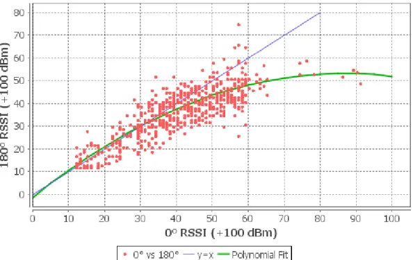
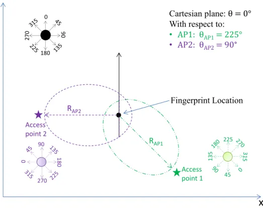
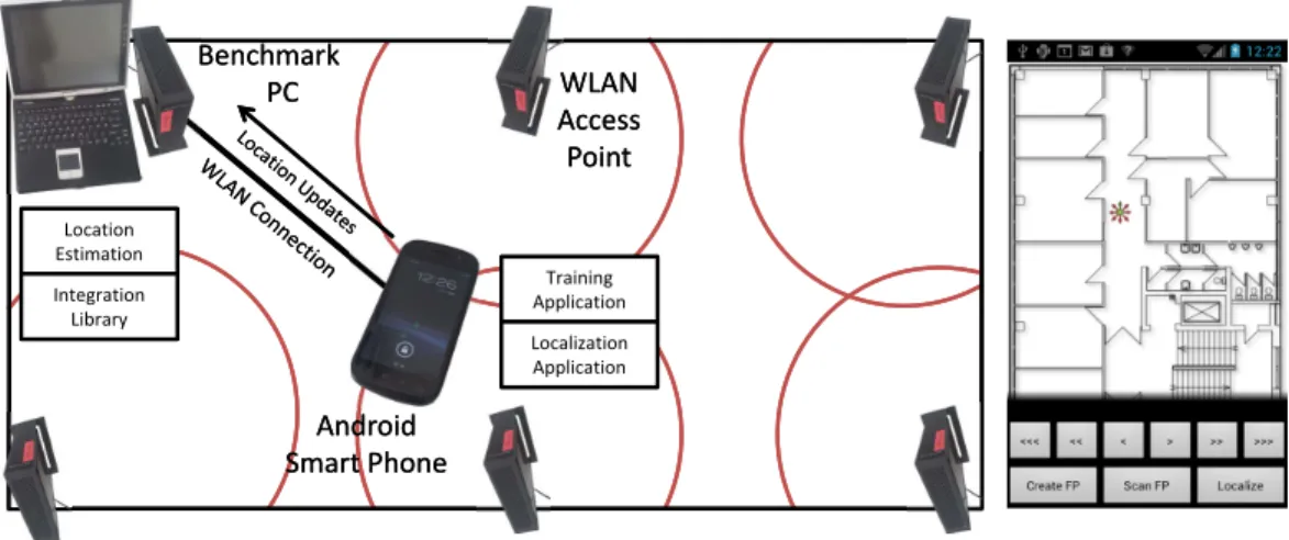
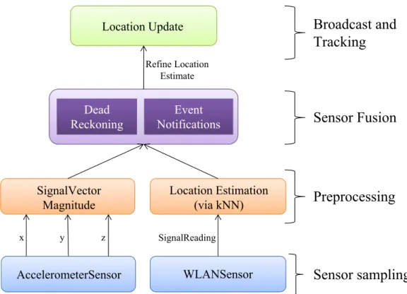
Abstract ix 1 Introduction 1 1.1 Motivation . . . 1 1.2 Challenges . . . 3 1.2.1 Deployment . . . 4 1.2.2 Maintenance . . . 7 1.3 Contributions . . . 8 1.4 Structure . . . 10
2 Background & Related Work 11 2.1 Setup . . . 11
2.2 Calibration . . . 14
2.2.1 Signal Propagation Modeling . . . 15
2.2.2 Scene Analysis . . . 16 2.3 Localization . . . 19 2.3.1 Geometric Techniques . . . 19 2.3.2 Statistical Techniques . . . 24 2.3.3 Particle Filtering . . . 26 2.3.4 Other Classifiers . . . 29 2.3.5 Application Architectures . . . 30 2.4 Maintenance . . . 31 2.4.1 Performance Monitoring . . . 32 i
ii CONTENTS
2.4.2 System Recalibration . . . 33
2.5 Summary . . . 34
3 Setup & Calibration Optimization 35 3.1 Preliminaries . . . 36
3.2 Enhanced Calibration . . . 38
3.3 Signal Attenuation Modeling . . . 40
3.3.1 Literature Review . . . 40
3.3.2 RSSI Distribution Analysis . . . 42
3.3.3 Signal Attenuation Modeling . . . 44
3.3.4 Empirical Determination of Coefficients . . . 46
3.3.5 Multiple Signal Sources . . . 50
3.3.6 Application to Localization System Deployments . . . 51
3.3.7 Summary . . . 54
4 Localization Optimization 55 4.1 Preliminaries . . . 56
4.2 Requirements . . . 56
4.3 Localization & Tracking . . . 58
4.3.1 Dead-reckoning . . . 59 4.3.2 Environmental Events . . . 61 4.4 Implementation . . . 62 4.5 Summary . . . 67 5 Maintenance Optimization 69 5.1 Preliminaries . . . 70
5.2 Infrastructure-based System Maintenance . . . 72
5.2.1 Literature Review . . . 73
5.2.2 System Setup . . . 75
5.2.3 Signal Change Detection . . . 77
5.2.4 System Recalibration . . . 79
5.2.5 Summary . . . 82
5.3 User-based System Maintenance . . . 84
5.3.1 Literature Review . . . 85
CONTENTS iii
5.3.3 Signal Displacement Detection . . . 88
5.3.4 Displacement Detection Evaluation . . . 94
5.3.5 Autonomous Recalibration . . . 103 5.3.6 Summary . . . 105 5.4 Optimization Summary . . . 106 6 Evaluation 107 6.1 Metrics . . . 107 6.1.1 Accuracy . . . 107 6.1.2 Precision . . . 108 6.1.3 Complexity . . . 108 6.1.4 Robustness . . . 109 6.1.5 Scalability . . . 109 6.1.6 Cost . . . 109 6.1.7 Summary . . . 110
6.2 Calibration Optimization Evaluation . . . 111
6.2.1 Signal Precision . . . 111
6.2.2 General Applicability . . . 116
6.2.3 Localization Performance . . . 119
6.2.4 Mapping Effort . . . 122
6.2.5 Summary . . . 123
6.3 Localization Optimization Evaluation . . . 124
6.3.1 Steps and Distance Estimation . . . 124
6.3.2 LOCOSmotion Localization System . . . 124
6.3.3 Summary . . . 128
6.4 Maintenance Optimization Evaluation . . . 129
6.4.1 Infrastructure-based System Adaptation . . . 129
6.4.2 User-based Dynamic Recalibration . . . 141
6.5 Evaluation Summary . . . 153
7 Conclusions & Outlook 155 7.1 Conclusions . . . 156
7.2 Outlook . . . 157
List of Figures
2.1 Localization System Deployment Lifecycle . . . 12
2.2 Intersection of Angle Direction Lines . . . 20
2.3 Lateration with Multiple Reference Points . . . 22
2.4 Intersection of Multiple Hyperboloids in TDOA Lateration . . . 23
2.5 Summary of Localization Technologies and Approaches [GLN09] . . . 30
3.1 Sample fingerprints from access points (AP) at multiple locations . . . 36
3.2 Calibration path within Indoor Area . . . 38
3.3 Assigning Location To Measurements to Create Fingerprints . . . 39
3.4 Signal distribution (in dBm) with distance . . . 43
3.5 Signal distribution (in dBm) with distance with overlaid oval pattern . . . 44
3.6 Degenerating elliptical regression . . . 45
3.7 Properties of an ellipse . . . 46
3.8 Setup for Empirical Rotation Coefficient Determination . . . 47
3.9 RSSI variations with respect to strongest RSSI . . . 48
3.10 Orientation adjustment per access point . . . 53
4.1 Accelerometer magnitude pattern for movement . . . 59
4.2 LOCOSmotion System Overview . . . 63
4.3 LOCOSmotion Implementation Overview (with app screenshot) . . . 64
4.4 LOCOSmotion Localization Subsystem . . . 66
5.1 Localization System Maintenance Lifecycle . . . 70
5.2 Overview of system deployment setup . . . 76
5.3 Link quality change detection in mesh network . . . 77
5.4 Correlation of access point and mobile device RSSI measurements . . . 80
5.5 Building floorplan with access point layout and Voronoi partitions . . . 81
5.6 RSSI Distribution for IEEE 802.11 Signal at fixed Location . . . 89
5.7 Access Point Deployment in Office Building . . . 95 v
vi LIST OF FIGURES
5.8 Displaced vs Detected Signal Sources for Different Locations . . . 99
5.9 Average RSSI delta per cell for displaced access points . . . 102
6.1 Office Building with Overlaid Grid . . . 112
6.2 Evaluation radio map generation by means of attenuation model . . . 113
6.3 RSSI Deviation for Office Building . . . 114
6.4 RSSI Deviation per Location for Office Building . . . 115
6.5 RSSI Deviation for Radio Maps in Library . . . 117
6.6 RSSI Deviation per Location in Library . . . 117
6.7 RSSI Deviation for Radio Maps in Home Environment . . . 118
6.8 RSSI Deviation per Location for Home Environment . . . 118
6.9 Localization Evaluation Configuration . . . 119
6.10 Localization cumulative error distribution . . . 120
6.11 Localization cumulative error distribution with radio maps from different persons . . . 121
6.12 Multi-orientation mapping effort . . . 122
6.13 Office Building Trace Path . . . 125
6.14 Probability Distribution of Errors . . . 126
6.15 Cummulative Probability Distribution of Errors . . . 127
6.16 Office Building Deployment . . . 130
6.17 Signal differences for AP3 in different configurations . . . 131
6.18 Configurations for Localization Performance Evaluation . . . 134
6.19 Localization Error Distribution With All Fingerprints . . . 136
6.20 Localization Error Distribution With Affected Fingerprints . . . 138
6.21 Signal RSSI Delta Per Location for one Access Point . . . 145
6.22 Signal probability distribution for one access point in different environments 146 6.23 Average RSSI Delta Per Cell for False Positive Recalibration . . . 147
6.24 Localization Error Distribution for Displacement of Half the Deployed Signal Sources . . . 150
6.25 Localization Performance Comparison Over Successive Displacements in Trade Fair Environment . . . 151
List of Tables
3.1 Excerpt of the Ellipse Lookup Table (in dBm) . . . 51
5.1 Detection rate for varying number of Deployed and Displacements access points - (false positives in braces) . . . 97
5.2 Number of detected displacements per quadrant in Office deployment with 10 access points . . . 101
6.1 Correlation of model-generated RSSI to Measured RSSI . . . 114
6.2 Total average error (cells) per orientation . . . 120
6.3 Total average error (cells) per orientation (cross-person) . . . 121
6.4 Average RSSI delta for the different configurations . . . 132
6.5 Localization average error distance (m) - all fingerprints . . . 135
6.6 Localization average error distance (m) - affected fingerprints only . . . 139
6.7 Pearson Correlation of a Signal Source in the Different Environments . . . 143
6.8 Maximum Signal Delta (dBm) in 90th percentile of Distribution . . . 147
6.9 Localization Average Error Distance (m) with half of the deployed signal sources displaced . . . 149
Abstract
Pervasive computing envisions the achievement of seamless and distraction-free support for tasks by means of context-aware applications. Context can be defined as the information which can be used to characterize the situation of an entity such as persons or objects which are relevant for the behaviour of an application. A context-aware application is one which can adapt its functionality based on changes in the context of the user or entity. Location is an important piece of context because a lot of information can be inferred about the situation of an entity just by knowing where it is. This makes location very useful for many context-aware applications. In outdoor scenarios, the Global Positioning System (GPS) is used for acquiring location information. However, GPS signals are relatively weak and do not penetrate buildings well, rendering them less than suitable for location estimation in indoor environments. However, people spend most of their time in indoor locations and therefore it is necessary to have location systems which would work in these scenarios.
In the last two decades, there has been a lot of research into and development of indoor localization systems. A wide range of technologies have been applied in the development of these systems ranging from vision-based systems, sound-based systems as well as Radio Frequency (RF) signal based systems. In a typical indoor localization system deployment, an indoor environment is setup with different signal sources and then the distribution of the signals in the environment is recorded in a process known as calibration. The distribution of signals, also known as a radio map, is then later employed to estimate location of users by matching their signal observations to the radio map. However, not all the different signal technologies and approaches provide the right balance of accuracy, precision and cost to be suitable for most real world deployment scenarios. Of the different RF signal technologies, WLAN and Bluetooth based indoor localization systems are the most common due to the ubiquity of the signal deployments for communication purposes, and the accessibility of compatible mobile computing devices to the users of the system.
Many of the indoor localization systems have been developed under laboratory con-ix
x ABSTRACT
ditions or only with small-scale controlled indoor areas taken into account. This poses a challenge when transposing these systems to real-world indoor environments which can be rather large and dynamic, thereby significantly raising the cost, effort and practicality of the deployment. Furthermore, due to the fact that indoor environments are rarely static, changes in the environment such as moving of furniture or changes in the building layout could adversely impact the performance of the localization system deployment. The sys-tem would then need to be recalibrated to the new environmental conditions in order to achieve and maintain optimal localization performance in the indoor environment. If this happens regularly, it can significantly increase the cost and effort for maintenance of the indoor localization system over time.
In order to address these issues, this dissertation develops methods for more efficient deployment and maintenance of the indoor localization systems. A localization system deployment consists of three main phases; setup and calibration, localization and main-tenance. The main contributions of this dissertation are proposed optimizations to the different stages of the localization system deployment lifecycle.
First, the focus is on optimizing setup and calibration of fingerprinting-based indoor localization systems. A new method for dense and efficient calibration of the indoor envi-ronmental areas is proposed, with minimal effort and consequently reduced cost. During calibration, the signal distribution in the indoor environment is distorted by the presence of the person doing the calibration. This leads to a radio map which is not a very accurate representation of the environment. Therefore a model for WLAN signal attenuation by the human body is proposed in this dissertation. The model captures the pattern of change to the signal due the presence of the human body in the signal path. By applying the model, we can compensate for the attenuation caused by the person and thereby generate a more accurate map of the signal distribution in the environment. A more precise signal distribution leads to better precision during location estimation.
Secondly, some optimizations to the localization phase are presented. The dense finger-prints of the environment created during the setup phase are used for generating location estimates by matching the captured signal distribution with the pre-recorded distribution in the environment. However, the location estimates can be further refined given additional context information. This approach makes use of sensor fusion and ambient intelligence in order to improve the accuracy of the location estimates. The ambient intelligence can be gotten from smart environments such as smart homes or offices, which trigger events that can be applied to location estimation. These optimizations are especially useful for indoor
xi
tracking applications where continuous location estimation and accurate high frequency location updates are critical.
Lastly, two methods for autonomous recalibration of localization systems are presented as optimizations to the maintenance phase of the deployment. One approach is based on using the localization system infrastructure to monitor the signal characteristic distribution in the environment. The results from the monitoring are used by the system to recalibrate the signal distribution map as needed. The second approach evaluates the Received Signal Strength Indicator (RSSI) of the signals as measured by the devices using the localization system. An algorithm for detecting signal displacements and changes in the distribution is proposed, as well as an approach for subsequently applying the measurements to update the radio map. By constantly self-evaluating and recalibrating the system, it is possible to maintain the system over time by limiting the degradation of the localization perfor-mance. It is demonstrated that the proposed approach achieves results comparable to those obtained by manual calibration of the system.
The above optimizations to the different stages of the localization deployment lifecyle serve to reduce the effort and cost of running the system while increasing the accuracy and reliability. These optimizations can be applied individually or together depending on the scenario and the localization system considered.
1
INTRODUCTION
Pervasive computing envisions the achievement of distraction-free support for everyday tasks by means of context-aware applications. Context can be defined as the information which can be used to characterize the situation of an entity such as persons or objects which are relevant for the behaviour of an application. Context-aware applications are applications which can adapt their functionality based on changes in the context of the user of the application. The applications must consequently be able to perceive their context and use it as input for adaptation. Location is an important piece of context information and it can be determined in outdoor scenarios by means of the Global Positioning System (GPS). However, GPS does not work in indoor settings which happens to be where people spend the most time. Therefore it is necessary to have location systems which would work within indoor environments. Indoor localization systems pose a different set of challenges for their deployment and maintenance compared to outdoor localization systems. In this dissertation, we propose some approaches to optimizing the deployment life cycle of indoor localization systems by addressing challenges from the initial setup through to maintenance of the systems. This chapter first presents the motivation for the work described in this dissertation and then proceeds to outline previous work and the existing challenges in the localization system deployment lifecyle. Next, some optimizations for the different stages of the deployment lifecycle are presented, which form the major contributions of this work. Finally, at the end of this chapter is an overview of the structuring of the remainder of this dissertation.
1.1
Motivation
The past two decades have seen immense advances in miniaturization of microelectronics which has resulted in the widespread availability of powerful mobile computing devices. Not only has the computing power of these devices increased over time, but the number of sensors which can be used to perceive and sense the environment has increased as well.
2 1. INTRODUCTION
These devices enable their users to accomplish more with the help of computing in their daily lives, and has ushered in the era of ubiquitous computing as originally envisioned by Mark Weiser [Wei91]. Ubiquitous computing enables distraction-free support for ev-ery tasks performed by people through the use of mobile computers which are embedded into everyday objects. Examples of ubiquitous applications in everyday life include home automation systems which can dynamically switch on or off the light and heating depend-ing on whether there are persons present in a room or not. Other examples include an application which selects the closest printer to a user when creating a print job in an of-fice environment, or a mobile device switching to silent mode and auto-responding to all incoming calls when a user is driving or in a meeting. In these scenarios, and more like them, the applications and embedded devices in the environment are able to dynamically adapt their behaviour depending on the current situation (context) of the user.
Location is an important piece of context because a lot of information about the situ-ation and activity of an entity can be inferred just by knowing where it is. For example, being in a conference room implies with high probability that the user is in a meeting, meanwhile the kitchen implies eating or cooking, or being at the gym implies working out. In addition, knowledge about which other users are in proximity of a particular user en-ables even greater possibilities for group dynamics. This enen-ables possibilities for location information to be combined with other sources of context to create powerful user experi-ences in context-aware applications. In outdoor scenarios, there is the global availability of the GPS which enables devices to estimate their location to within 1m to 3m (depending on the application). The GPS system is made up of a constellation of satellites which broadcast radio signals containing the satellite position and atomic clock time at regular intervals [ME06]. Devices with the appropriate GPS receivers capture the signals and use the time-of-flight to calculate the distance from the satellite. With the signals from three or more satellites, it is possible for the device to use lateration to estimate the location of the receiver. However, GPS signals are rather weak and do not penetrate buildings well, rendering them less than suitable for location estimation in indoor environments [HB01].
The rise in affordable mobile computing over the past decade has seen a correspond-ing increase in research and development of indoor localization systems. The advances in miniaturization of computing technology in the past decade have led to broader accessibil-ity of powerful mobile computing devices with a wide range of sensors and ushered in a new era of mobile computing. The sensors on mobile computing devices can be applied to deter-mining the context of the entity in an automated fashion. These advancements, combined
1.2. CHALLENGES 3
with the rise in performance and ubiquity of wireless networks have ushered in a new era for location-aware mobile applications which can assist in daily tasks seamlessly. A wide range of technologies have been used for indoor localization systems, such as vision-based systems [FS02] [KJ08] [MWBS09], audible sound [LHM+06] [MLG+05] and ultrasound-based [WJH97] [BLO+05] systems, as well as Radio Frequency (RF)-based systems. The most common radio signals used include FM signals [MPOMI10] [YLYR15], Global Sys-tem for Mobile Communications (GSM) [OV05] [VdLH+07], Radio Frequency Identifier
(RFID) [CJJA04] [NLLP04], Ultra-wideband (UWB) [IHQ04], Wireless Local Area Net-works (WLAN) [BP00], Bluetooth [FDW04] and Infrared [WHFG92], among others. The different technologies come with different trade-offs in terms of localization accuracy, dura-bility and cost [LDBL07] [GLN09]. Of the different technologies available, RF-based signal technologies are the most attractive, with WLAN-based localization systems being the most proliferated due to the broad deployments of WLAN network infrastructure and broad adoption of WLAN-compatible mobile devices [Mau12]. The combination of both factors reduces the deployment and usage cost, as well as limiting the additional infras-tructural requirements for the deployment.
However, many of the localization systems have been developed in laboratory condi-tions or in controlled environments and therefore achieve optimal performance in these scenarios. In larger scale and longer term deployments in real-world scenarios, there are challenges with respect to the cost and effort required for initial setup and maintenance of performance characteristics over time for indoor localization systems. In the following sections, we examine some of the different challenges facing indoor localization systems which are particularly relevant to this dissertation.
1.2
Challenges
Although there has been much advance in the research and development of indoor local-ization system technologies, there are also several outstanding challenges which face the deployment and maintenance of these systems. The different challenges affect the feasibil-ity, accuracy, cost and therefore, the adoption of indoor localization systems in real-world large-scale deployments. In this section, we look into more detail at some of the challenges during the different phases of the life cycle of indoor localization systems.
4 1. INTRODUCTION
1.2.1
Deployment
The deployment of an indoor localization system involves the setup of the infrastructural hardware and calibration of the equipment so as to enable location estimation functionality within the said environment. The setup and calibration of large indoor environments naturally incurs a certain amount of effort and cost which is more or less depending on the technologies used. In addition, an accurate calibration of the system is important to ensure the accuracy and precision of the location estimation during online operation of the system. All these are important determinant factors that could either limit or encourage adoption of indoor localization systems. We now examine the infrastructure requirements, calibration effort and further how they affect the accuracy and precision of the indoor localization systems.
Infrastructure Requirements
The infrastructure requirements include all the hardware and software components required for the setup and deployment of the indoor localization system, as well as all the hardware and software required in order to use the system. Hardware costs are usually directly proportional to the size of the indoor area to be covered, whereas software costs scale much easier. Software can easily be reused in deployments with little or no modifications which enables the software development costs to be amortized over several localization system deployments. On the other hand, the cost for acquiring and deploying hardware can be very high depending on the scenarios involved. In addition, the hardware costs for the users of the system need to be kept as low as possible, as there are usually many more users of the system than there are devices deployed in the infrastructure. Therefore it is usually of great benefit when existing user devices or infrastructural hardware can be re-used for indoor localization purposes.
Ultrawide-band and ultrasound positioning systems usually require specialized equip-ment to be deployed in order to achieve indoor positioning. This equipequip-ment is usually costly [LDBL07] and this limits the adoption of such systems especially on a large scale. Localization systems based on RFID require a deployment of RFID readers which are not cheap. The readers pick up measurements from the tags and use the RSSI for location esti-mation. The more RFID readers are deployed in an environment, the higher the accuracy of the system and also the higher the cost of the system. Passive RFID communication is usually very short distance and therefore it is common to deploy more readers in order to get good results. The LANDMARC [NLLP04] system tries to work around this by having
1.2. CHALLENGES 5
fewer readers and instead placing many reference (active) RFID tags in the building. It achieves an average accuracy of less than 2m and 50% within 1m. But this approach also requires the users of the system to carry RFID readers which can be a source of significant cost overhead and a severe limitation to system adoption. GSM systems have little over-head cost for use in indoor localization as the infrastructure is already broadly deployed for mobile telephone networks. However the relatively large range of GSM signals renders them less than ideal for indoor localization systems.
IEEE 802.11 (WLAN) signals are also commonly used in indoor localization system deployments. The widespread (and growing) deployments of WLAN networks at public buildings and even on large scales (such as city-wide WLAN) allows indoor localization systems based on this technology based on this signal technology to leverage a lot of existing infrastructure. This significantly reduces the deployment and set up costs. In most cases, only a few more signal sources need to be added to the deployments in order to augment the deployment setup depending on the required signal source density. Furthermore, the vast majority of mobile devices sold today support WLAN networks for communication and have powerful computing chipsets, which makes them suitable for use in localization. This means the users of the WLAN-based indoor localization system do not require any extra hardware to use the system. The indoor localization system becomes mostly a software solution which is layered over the existing infrastructure.
The challenge for most real-world indoor localization systems is keeping the costs for infrastructure setup and deployment as low as possible, while achieving and maintaining high accuracy and precision for the localization system. Furthermore, as more more tech-niques for efficient and accurate localization are developed, it is crucial for the approaches to be easy and cost-effective to retrofit onto existing system deployments. New techniques which require complete redeployment of existing systems are much more costlier and suffer from low adoption rates as a result.
Calibration Effort
The initial calibration entails all the configuration and training which is required to get the positioning system up and running in the indoor environment. The calibration required generally depends on the type of positioning system being deployed. Signal propagation based indoor localization systems typically have no time-consuming manual fingerprinting process for bootstrapping the system. However, the complexity for generating robust propagation models for achieving high accuracy is significantly high. In
fingerprinting-6 1. INTRODUCTION
based indoor localization systems, the manual calibration is typically a very time consuming process. Previous research shows that the denser the environment grid, the better the localization accuracy. Fingerprinting an area with many more cells also requires much more effort for making fingerprints in each cell. Higher human effort for localization implies higher costs for deployment. The automation of calibration through the use of robotics is limited due to the bootstrapping problem; the robots themselves need to know where they are in order to accurately navigate and calibrate the indoor environment. Simultaneous Localization and Mapping (SLAM) is one promising area in this regards, however, the technology is still very expensive at this point to justify its application as a cost-saving measure for calibration. This means that in most cases, a person (trainer) manually goes around the environment making the fingerprint measurements. However, the human body attenuates WLAN signals significantly and therefore distort the fingerprints collected for the radio map. Therefore, the orientation of the trainer is another factor which significantly impacts the quality of the fingerprint radio map during calibration. In fingerprint-based systems, the quality of the signal distribution radio map is of high priority and has a direct correlation to the localization performance of the system during online operation.
Accuracy & Precision
Accuracy and precision are very important characteristics of an indoor localization system. The accuracy of a system is commonly evaluated by means of the average error distance metric. This is computed as the average Euclidean distance between the estimated location and the actual location of the target. The smaller the average distance error, the higher the accuracy, and the better the system. On the other hand, the precision of a system considers how consistently the system performs. This is often measured in terms of the distribution of the distance error between the estimated and true location over a sample of location estimates. Precision is a measure of robustness of the system over time. Localization systems which use symbolic location representation may not be able to represent accuracy as the average distance error. The accuracy in such systems can be quantified by overlaying an arbitrary grid of cells over the indoor area. Each cell then becomes a unit of distance from which the average error can be computed.
There are several factors affecting the accuracy and precision of indoor localization systems. In RF-based systems, one common challenge is that the RSSI signals experience fluctuations and are not static values, which is one of the reasons why probabilistic local-ization algorithms usually perform better than deterministic ones. The measurement of an
1.2. CHALLENGES 7
RSSI signal at a specific location over time will produce variations in the value measured over time. The WLAN signals are also susceptible to attenuation by other factors such as the presence of persons and objects in the indoor environment, the walls, floors, ceiling and other architectural constraints, and even the orientation of the user when making a measurement observation for location estimation [VA14]. This distorts the measured RSSI of the signal even during the calibration phase and negatively affects the indoor localization system.
As previously mentioned in Section 1.1, there are a lot of different signal technologies which can be used to develop indoor localization systems with varying degrees of accuracy and precision, as well as corresponding varying costs. While very accurate and precise indoor localization systems are desirable, a highly precise system is not very useful if the deployment costs are prohibitively high and its use limited to laboratory studies and conditions. The challenge is striking the right balance between a system with good-enough accuracy which is cheaper to deploy, and a very costly one which is prohibitively expensive. The threshold for ”good-enough” accuracy depends on the intended use of the localization system. An even better approach is to reduce the cost of deployment and maintenance of existing systems without adversely impacting the localization performance.
1.2.2
Maintenance
Due to the fact that indoor environments are rarely static, changes in the environment such as moving of furniture or building layout could adversely impact the localization system performance. A regular recalibration of the system to the new environmental conditions is therefore required in order to restore and maintain optimal localization performance in the indoor environment. When this happens regularly, it can significantly increase the cost and effort for maintenance of the indoor localization system over time. In order to increase the acceptance, practicality and deployment of indoor localization systems, it is necessary to optimize and automate their deployment and maintenance, while simultaneously reducing the associated cost and effort.
These changes in the environment layout might have significant impact on the signal distribution in the indoor environment and consequently have negative impact on the per-formance of the indoor localization system. It is therefore imperative that the localization system be robust to such changes in the environment. The changes in the indoor envi-ronment could be static or dynamic. Static changes are envienvi-ronmental changes which are permanent one-time changes that alter the environment in some way, such as the
displace-8 1. INTRODUCTION
ment of a large piece of furniture, or the addition of a wall within a building. On the other hand, dynamic changes could occur such as the coming and going of persons inside a large area such as a supermarket. Granted that the human body is mostly composed of water, the presence of the large number of people can significantly alter the signal characteristics distribution in the environment. Localization systems therefore need to be robust to these changes and maintain their performance characteristics over time.
The robustness of an indoor localization system characterizes the stability and consis-tency of the localization system performance in less than ideal situations. Such situations could arise due the absence of a signal source which used to be present in the environment, or even the presence of new ones. These signal sources may have been recorded in the initial calibration radio map and their absence renders the radio map out-of-date. More commonly, changes in the signal distribution do occur as a result of changes in the in-door environment layout such as displacement of furniture or even the signal source itself. Sometimes a signal source could be blocked or even malfunction. A robust system should optimally be able to detect changes to the initial calibration and adapt its operation to maintain its performance characteristics. In cases where an adaptation is not possible, it should still be able to notify the maintainers of the system that performance is not optimal so that the necessary manual recalibration steps can be taken.
1.3
Contributions
This dissertation presents several contributions related to the optimization of deployment and maintenance of indoor localization systems. In particular, the proposed optimizations serve to reduce the cost and effort, while improving localization performance of the systems. The focus in this work will be on WLAN fingerprinting-based indoor localization systems. These have the broadest ecosystem of deployment and supported hardware which enhances adoption and makes deployments more cost effective. Also, the contributions proposed in this thesis are mostly software-based solutions which minimizes the cost which would be required for extra hardware equipment. This makes the proposed contributions easily applicable both to new and existing indoor localization systems, since software solutions typically cost less to retrofit onto existing deployments.
The first contribution is a method for scene analysis which enables faster, more precise capturing of the signal distribution in an environment. Scene analysis is typically performed manually by a person using a measuring device to capture the characteristic RSSI at known
1.3. CONTRIBUTIONS 9
locations throughout an indoor environment. This procedure is known as fingerprinting and can require significant effort when mapping large areas. We propose a method for more efficient fingerprinting with significant savings in the effort required, while improving the quality of the captured signal distribution. WLAN signals are significantly attenuated by the human body, and consequently the person calibrating the localization system distorts the signals measured. This results in a radio map which is distorted from the actual signal distribution in the environment. In order to counteract this, we develop a model that captures the attenuation effect of the human body on WLAN signals. By applying the model to the captured signal characteristics, it is possible to compensate for the distortion caused by the presence of the trainer and thereby more accurately capture the signal distribution in the environment. Ambient context information incorporated via sensor fusion can refine location estimates and enable indoor tracking .
Furthermore, an approach for monitoring and recalibration of indoor localization sys-tems using the system infrastructure is proposed. Significant changes in the signal distri-bution would typically correspond to environmental layout changes which render the initial calibration outdated. The localization performance of the system suffers as a result. Our approach enables detection of such changes in the environment and autonomous recalibra-tion of the radio map to match the current signal distriburecalibra-tion within the environment.
Lastly, this dissertation proposes an algorithm for signal source displacement detection using only the measurements generated by the mobile devices using the localization system. The algorithm filters and analyzes measurements made by user devices to detect faulty or displaced signal sources. In addition, the user measurements are also applied to recali-brating the localization system in order to limit the performance degradation caused by the environmental changes. The proposed approach enables the system to autonomously monitor its performance, check for changes in the deployment which adversely impact lo-calization performance and compensate for the changes. This significantly reduces the manual effort and cost for maintaining the system over time.
The major contributions of this dissertation have been published at different presti-gious scientific conferences such as the ACM International Joint Conference on Pervasive and Ubiquitous Computing [FHM13], Journal of Ambient Intelligence and Smart Envi-ronments, International Conference on Intelligent Environments [FHM16], International Conference on Indoor Positioning and Indoor Navigation, Springer Communications in Computer and Information Science [FHWM13b] [FHWM13a]. The results obtained from the research have also been applied in commercially deployed indoor localization systems.
10 1. INTRODUCTION
1.4
Structure
The rest of this dissertation is structured as follows. The next chapter provides background into the concepts underlying indoor localization systems as well as presents an overview of the lifecycle of their deployment and operation. The state of the art at each stage of the life cycle is also presented. The subsequent chapters present optimization for the different stages of the localization lifecycle.
In Chapter 3, some methods are presented for optimizing the initial calibration effort and precision through a combination of novel techniques for fingerprinting and a model for signal attenuation caused by the human body. Chapter 4 follows with optimizations to location estimation with respect to indoor tracking applications through the application of sensor fusion and ambient intelligence. In Chapter 5, some optimizations for autonomous system monitoring and adaptation are presented – one using autonomous infrastructure-based system adaptation, and the other, an algorithm for signal displacement detection and autonomous recalibration using measurements generated during active usage of a lo-calization system.
The optimizations are then extensively evaluated in Chapter 6 with an analysis of the effect of the methods and algorithms on the localization performance of the systems in different environments and scenarios. Finally, Chapter 7 concludes with a summary of the proposed optimizations and an outlook for future research directions.
2
BACKGROUND &
RELATED WORK
In order to better understand the scope of our contributions in the optimization of deploy-ment and maintenance of indoor localization systems, it is necessary to understand the different stages of the deployment and operation of an indoor localization system. This chapter provides an overview of the deployment lifecycle of an indoor localization system, as well as a review of the state-of-the-art in indoor localization at the different stages of the lifecycle. Given the widespread availability and adoption of RF-based signal technologies, this chapter focuses on the system deployment life cycle of RF-based indoor localization systems.
The deployment of a localization system can be typically broken down into three stages - setup & calibration, online localization, and system maintenance. In the setup and calibration phase, the signal sources are deployed in the area to ensure optimal coverage of the environment by multiple signals at each location. Then the system is calibrated with the distribution of the signals in the environment. The signal distribution is then used to train the algorithms for localization in the next phase. After the system is deployed and operational, it needs to be continuously monitored in order to adapt to any changes in the environment and maintain the performance characteristics of the system. The localization system deployment lifecyle is summarized in Figure 2.1
In the following sections, each of the stages of the lifecycle will be examined in depth, beginning with the initial setup and calibration, and then proceeding to examine different location estimation techniques. Finally, this chapter takes a closer look at maintenance phase of localization system deployments and the different existing approaches.
2.1
Setup
Over the years, several different technologies for enabling indoor localization systems have been developed such as vision-based systems, audible sound and ultrasound based systems and Radio Frequency-based systems [Mau12]. The RF-based systems range from GSM
12 2. BACKGROUND & RELATED WORK
Setup & Calibration
Localization
Maintenance
Dynamic System Monitoring
Figure 2.1: Localization System Deployment Lifecycle
[DOAD09], RFID [NLLP04], Bluetooth [BHI+04] [ASS+10], WLAN [BP00] [YA08] among
others, as well as hybrid combinations thereof [HVJS07] [BSJL11]. Just like the GPS sys-tem makes use of satellites, RF-based indoor localization syssys-tems require a signaling syssys-tem in order to be able to create location estimates. The signal sources need to be distributed in the environment in such a way as to provide ample coverage of the whole indoor area and enable accurate location estimation. The different technologies have varying environ-mental and infrastructural requirements for the use. For example, vision-based systems require the installation of multiple cameras in the environment such as to generate images of the whole environment. The limited field of vision of most camera systems means that several units need to be installed to cover the whole area, which gets expensive for very large indoor areas. Other light-based systems such as laser-based indoor localization sys-tems also require extra hardware to be installed in the environment and linked together so as to be able to process the input from the sensors. Similarly, sound-based systems require hardware deployments in addition to the typically existing communications infrastructure. This can lead to high costs and effort for the system setup, which together with the ad-ditional privacy concerns of constant audio and visual monitoring, increase the inertia to adoption of these systems.
pop-2.1. SETUP 13
ular in research and real-world deployments due to their relatively better performance and cost/benefit ratio [LDBL07]. RF-based systems rely on the physical properties of the electromagnetic wave transmission for location estimation, hence the need for signal trans-mitters and receivers in the indoor environment. Just like GPS satellites which orbit the earth in a carefully planned constellation to maximize coverage of the earth’s surface, so too signal transmitters in indoor environments need to be setup so as to provide optimal coverage of the environment. Optimal coverage seeks to maximize the differentiation in signal space of different locations within the environment through multiple visible signals at all locations [MHDL12] while minimizing the number of signal sources required. The amount of transmitters required depends on the type of RF-signal used, since the signals each have different wavelengths and consequently varying ranges. RFID signals, for ex-ample, have very limited range and thus would require more hardware infrastructure in order to cover the whole environment. Previous research [WHZM12] has also analyzed the optimal RFID tag deployment for indoor localization. On the other hand, GSM and FM signals have longer wavelengths and much broader range compared to RFID signals. This means that indoor localizations systems based on these signals typically require little to no extra infrastructural setup. It is possible to simply re-use existing broadcast signals. In addition to the range of the signals, the permeability of the signal through walls is another factor which influences the deployment setup. While signals which easily travel through indoor building materials allow for less signal sources in the deployment, it is also desirable to have signal distribution characteristics which are delineated by the environment layout. Signals which are blocked and attenuated by the indoor environment tend to have more unique characteristics at different locations in the building and therefore are better suited for indoor localization. On the other hand, signals such as FM or GSM signals which permeate through walls and buildings easily tend to have similar characteristics over wide areas. The lack of unique traits within different sections of the indoor environment makes it more difficult to uniquely characterize the signal distribution in particular areas and hence, it is harder to compute location estimates with only a few signal sources. Bluetooth and WLAN-based indoor localization systems are the most common due to their added utility as mediums for inter-device and network communications. This allows for re-use of the existing communications infrastructure for localization purposes. Furthermore, the transmitters for these signals are very affordable, which makes it cost-effective to deploy enough signal sources in even large indoor areas compared to other RF-based technologies. The widespread availability of Bluetooth and WLAN-capable mobile devices means that
14 2. BACKGROUND & RELATED WORK
more users and use-cases can benefit from their use in system deployments.
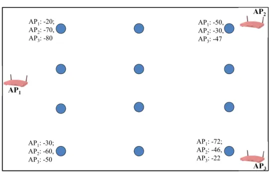
Even though signal sources such as WLAN access points for communications may be reused for localization, the optimal deployment setup of signal sources for communications may not necessarily be the same setup which is optimal for indoor localization purposes. There have been strategies developed over the years for optimal communication network deployment setups [LKC02] [VHH07]. However, indoor localization typically requires a denser signal distribution than is needed for simple communication networks. Just like in GPS, multiple visible signals are required for location estimation via triangulation or similar techniques. Typically, at least three or more signal sources are necessary to apply such localization techniques, with a higher number of visible signals being preferred for larger indoor environments and better accuracy. However, setting up more access points is also more costly, therefore the goal of the deployment setup is to enable the visibility of a minimum viable number of signals at each location in the environment, while maximizing the distance in signal space between the physical locations. Previous research [MHDL12] [FL10] has been carried out into optimizing the deployment setup of signal sources by means of simulation models and experimental validation. Simulation provides a faster means of determining optimal placement of signal sources as opposed to manual setup and repeated testing which is costly and time-consuming [YWLZ11]. The manual approach is also not suitable for large indoor environments and hence undesirable. The authors in [KFG13] develop a model for simulation using tree graphs and simulated annealing to determine the optimal number and placement of WLAN access points for indoor localization. Simulated annealing is a probabilistic technique for solving bound-constrained optimization problems. The results obtained in previous work demonstrate that it is possible to minimize the cost of the deployment setup, while improving the localization system performance by applying an optimal setup of the signal sources in a given environment. This also serves to increase the adoption and utilization of indoor localization systems, especially for large buildings and indoor scenarios.
2.2
Calibration
After the signal sources have been deployed, the next step is the calibration of the system. During the calibration phase, the signal distribution characteristics in the environment are recorded so that they can be compared later to live measurements in order to generate a location estimate for a user. There are typically two ways by which the system calibration
2.2. CALIBRATION 15
can be accomplished: signal propagation modeling and scene analysis. In the following sections, we will examine both approaches in depth.
2.2.1
Signal Propagation Modeling
The goal of signal propagation modeling is to predict the path loss which will be experienced by a signal as it travels through a medium. Path loss (expressed in decibels) can be defined as the ratio of transmitted to received power. By accurately predicting the path loss of a signal in an environment, it is possible to automatically compute the corresponding RSSI distribution of the signal at different locations within the environment. Propagation models can be broadly categorized into three types: empirical, deterministic and stochastic [AWC+05].
Empirical models are based solely on observations of a signal traveling in a medium at a few known locations in an environment. The measurements are then extrapolated to build a propagation model for the signal in the given environment. Empirical models are typically effective only in free-space environment and do not account for the multi-path effects which occurs in indoor environments. Deterministic propagation models apply the laws of electromagnetic wave propagation in order to determine the RSSI of a signal at a given distance from its source. Deterministic models usually take many variables into account in order to generate accurate predictions of the signal path loss. Typically they require an accurate representation of the environment within which the signal is traveling, such as a 3-dimensional rendering of the location. Also, it is necessary to know what building materials were used in construction so as to compute the attenuation effect on the signal. The more variables are taken into account, the more accurate the model. However, this also leads to a corresponding rise in complexity of the modeling computation. Stochastic models are the least accurate of the three models, and they model the environment as a series of random variables. They also require the least information about the environment and consequently, have much less complexity and computing requirements.
Several different indoor localization systems have been built based on signal propagation modeling [LTK08] [LKC09] [AC07]. An empirical model for path loss indoor environments was proposed by Seidel et al [SR92] based on measured data at 914 MHz in multi-floored environments. The model takes attenuation factors of the floors and walls into account and they examine different locations as well. The path loss for WLAN signals also typically follows a log-normal distribution [Far05] [Kae06] and by applying a range of algorithms on the propagation models [GJ04] it is possible to estimate the location of a user. In addition,
16 2. BACKGROUND & RELATED WORK
Xiang et al [XSC+04] propose an empirical propagation model-based signal distribution
training scheme which reduces the training workload by using a few collected samples of the signal distribution as starting point for modeling. The system achieves 2m accu-racy with 90% probability for static position determination. However, the propagation of WLAN signals is difficult to accurately model due to the dense multi-path effects such as reflection, diffraction and scattering of the signal [KK04b]. In addition, the complexity of deterministic models and low accuracy of stochastic models are prohibitive factors hinder-ing their widespread use in indoor localization systems. Consequently, other approaches [LKHL06] have been developed which do not rely solely on the signal propagation, but also on minimal measurements in the environment in order to generate a signal distribu-tion map. The high number of variables involved in signal propagadistribu-tion modeling in indoor environments results in a high modeling effort. The alternative is a reduction in variables considered which reduces the overall accuracy of the signal distribution map. The alter-native to propagation modeling is to manually map the signal distribution characteristics and all accompanying multi-path effects through scene analysis.
2.2.2
Scene Analysis
Scene analysis covers the range of methods by which it is possible to survey an indoor area in order to capture characteristic signal properties at different locations in that environ-ment. Most commonly, this is accomplished by systematically making measurements at known locations throughout the indoor environment. These measured characteristics can be any properties of the signal which vary within the environment, and which by them-selves or in combination with other properties (of other signals) could be used to uniquely characterize a specific location in the indoor environment. In RF-based localization system deployments, the most commonly used characteristic is the RSSI of the signal, although other properties, such as the travel time of the signal from transmitter to receiver, could be employed as well. The person calibrating the system (also known as trainer) uses a measurement device to capture the certain properties of the signals at a specific location in the environment. This list of signals visible and their characteristics at a specific location are stored together with the location identifier as tuple, which is referred to as a fingerprint. The fingerprint therefore captures the RF signal characteristics for all access points at a specific location in an indoor environment.
The location component of the fingerprint can be captured in several different ways [BD05], depending on the location model used and the requirements of the specific indoor
2.2. CALIBRATION 17
environment and localization system [BBR02]. The most common location models used in indoor localization systems are geometric and symbolic models. Geometric models define position as coordinate tuples relative to a reference coordinate system. The reference co-ordinate system can be local to the environment, or global. For local geometric models, an arbitrary origin point is chosen within the indoor environment, and serves as the reference point for all other coordinates. Global geometric models typically make use of GPS coor-dinates which are widely understood and applicable. On the other hand, symbolic models use location-specific nomenclature and a purpose-built for specific use-cases. For example, the location names could be chosen by function such as Kitchen, Laboratory etc, or they could be chosen arbitrarily. Geometric models are typically used in systems where high precision is required, meanwhile symbolic location models are more applicable for coarse granularity, such as, room-level localization systems.
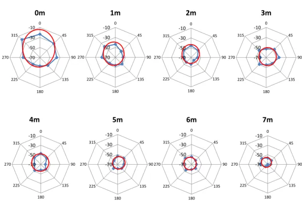
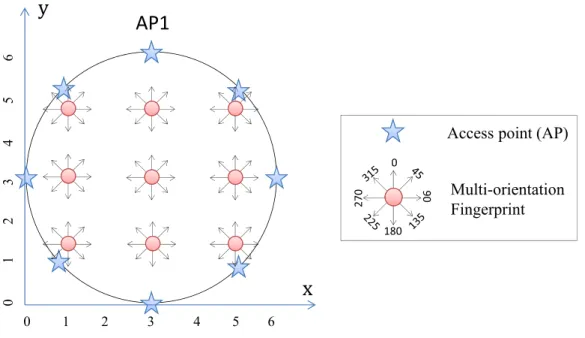
The second component of the fingerprint is the list of RSSI values for all the visible signals at the location. For WLAN signals, the signal strength (RSSI) is a measure of the power present in the received radio signal and is expressed in units of decibel meters (dBm). A higher value for the RSSI corresponds to a stronger signal in the environment. As a result of the dense multipath effects such as reflection, diffraction and scattering typ-ical in indoor environments, the RSSI for a signal at a given location fluctuates over time [KK04b]. Therefore during fingerprinting, typically the mean of several RSSI measure-ments is computed and saved as the observed RSSI value at a particular location. Another approach is to save the signal strength ratios between pairs of signal sources visible at a given location, instead of the absolute RSSI value for each access point [Kjæ11]. Further-more, due the high proportion of water in the makeup of the human body, the trainer also has an attenuation effect on the measured RSSI signals. It is therefore advantageous to get scans from multiple orientations of the same position in order collect more characteristic signal distribution in the indoor environment. Several studies [BP00] [Kae06] [KK04a] have demonstrated the adverse effects of the presence and orientation of the human body on the localization system performance.
The fingerprinting process is repeated multiple times at different locations in the envi-ronment in order to build a collection of fingerprints known as the radio map. The radio map captures the overall signal distribution for all signal sources in the indoor environ-ment. This radio map will later be used to train the algorithms during the localization phase. In typical deployments, the fingerprinting is done at multiple locations which are close to each other in other to have a dense fingerprint grid. The fingerprint grid density
18 2. BACKGROUND & RELATED WORK
improves the resolution of the localization error and thereby raises the overall system pre-cision. However, this approach of dense fingerprinting is very time consuming and requires much effort especially for large indoor areas. This has led to research and development of systems which seek to minimize the effort required for fingerprinting while not relying solely on signal propagation models.
Systems such as MapGENIE [PBD+14], ARIADNE [JBPA06] or [YLYR15] use a
mini-mal amount of fingerprints and some information about the indoor environment to generate a fingerprint radio map of the area. ARIADNE proposes to use a two-dimensional con-struction floor plan and a single RSSI measurement to generate an estimated radio map. MapGENIE goes further by incorporating measurements passively generated by pedestri-ans moving around the building, together with exterior information about the building in order to generate a radio map for training the localization algorithm. Both ARIADNE and MapGENIE thereby employ empirical signal propagation models which reduce the complexity of pure signal propagation models by incorporating actual measurements from the environment. SEAMLOC [RBO14] seeks to reduce the effort for initial calibration by combining an interpolation algorithm with signal characteristic measurements at fixed points in the environment in order to estimate location.
Simultaneous Localization and Mapping (SLAM) systems are calibrated by building a radio map of an environment while simultaneously determining the location of an ob-ject or person within the environment. The obob-ject being located often needs to rely on alternative sources of information for determining location while mapping, such as laser ranging, sonar-based or vision-based systems. Other external sources of information such as acceleration, compasses and GPS are often added into the mix. Sensor fusion is then performed to dynamically generate location estimates using all of the available input. The SLAM approach is particularly useful in robotics or robot-assisted fingerprinting scenarios where the robots use the alternative sensor inputs to map out the environment onto a specific location model while collecting scans of the RSSI distribution in the environment. However, the initial localization performance of these types of systems is typically low, and increases only over time and users. This introduces a dependency on the usage of the system which is undesirable in many scenarios.
After the indoor localization system is calibrated using any of the methods previously described, then it can be taken into live operation (”online” mode) for location estimation.
2.3. LOCALIZATION 19
2.3
Localization
During the localization phase, the system is put into live operation (often referred to as online mode), and used to provide location estimates for users in the indoor environment. In RF-based systems, the location estimation is done by recording the signal characteris-tics for the signals at the current user position in the environment, and then comparing these characteristics with the radio map from the calibration in order to find the closest match. The location of the closest match in the radio map is returned as an estimate for the user location. The process of matching the signal characteristics to a previously recorded pattern in the calibration radio map can be achieved using either deterministic or probabilistic techniques. There are different signal characteristics which can be measured in the environment and correspondingly different localization algorithms and techniques applicable for the different cases. In the following, we briefly examine the different signal characteristic properties and techniques applied for location estimation.
2.3.1
Geometric Techniques
RF signals are electromagnetic waves which are transmitted following a trajectory in a medium. The signals are detected by the modulation they cause when the wave arrives the antenna of the receiving device. The transmission of these signals in indoor environments lends them certain geometric properties such as the angle of arrival or time of arrival, which can be measured and characterized for different locations in the indoor environment. These properties can then be used for location estimation by applying different geometric tech-niques. In the following, we examine three classes of commonly used geometric techniques for location estimation - proximity, angulation and lateration.
Proximity
Proximity relies on a dense grid of antennas with fixed locations in an indoor environment, which monitor the environment for the presence of mobile agents. When a mobile agent is detected, the location of the antenna closest to the mobile agent is taken as the estimated location for the mobile agent. The metric for determining the ”closest” antenna to the mobile agent is the Received Signal Strength [AK11]. Basically, the antenna which picks up the strongest RSSI reading from the mobile agent is regarded as the closest one to it. If more than one antenna detected the signal, the location of the antenna with the strongest signal is used as the estimate [NLLP04]. The resolution of the accuracy of proximity-based
20 2. BACKGROUND & RELATED WORK
3
P
ߠ
ଶߠ
ଵFigure 2.2: Intersection of Angle Direction Lines
systems is thereby strongly dependent on the density of the antenna (receiver) grid in the deployment. The more antennas are deployed, the finer the resolution of the location estimates. This makes proximity-based localization systems suitable mostly for room-level localization, with symbolic and relative (to the antenna) location information. Proximity-based localization can be used with a wide range of signal systems, but most commonly it is used in RFID based systems. The short range of RFID signals increases the likelihood of a user being closer to the detecting antenna which is used as the location estimate. Cell identification (Cell-ID) is another example of proximity-based localization. It relies on the fact that mobile handsets tend to connect to the closest available cell tower, or in other words, the cell tower with the strongest RSSI. This enables the network to be able to identify the approximate position of a mobile device by knowing which cell tower the mobile devices is currently connected to [LDBL07]. The accuracy of Cell-ID is in hundreds of meters, meanwhile RFID-based proximity systems have a resolution of only a couple of meters. The accuracy of proximity-based systems therefore depends on the type and range of the RF-signal used.
Angulation
Angulation is location estimation by the intersection of several pairs of angle directional lines. This is also referred to as localization via Angle Of Arrival (AOA). The angle direction lines are formed by a circular radius from a signal source to the receiver. In order to obtain a two-dimensional location estimate, at least two reference points and two measured angles are required, as depicted in Figure 2.2 Similarly, at least three reference points and three measured angles are required for three-dimensional location estimate. Determining the angle of arrival requires directional antennae to be used in the system deployment. The phase difference between the received signals at each antenna are mapped
2.3. LOCALIZATION 21
to an incident direction of the signal. The incident direction lines are then extrapolated to compute the intersection and thereby generate a location estimate. Angulation can also provide orientation for indoor navigation [NN03] and the stability of the signal phase compared to RSSI can lead to better localization accuracy in some scenarios. However, AOA deployments typically have large and complex hardware requirements. Also, in order to achieve high accuracy the angle measurements need to be accurate, which is difficult to do in indoor environments fraught with dense multipath effects like diffraction, reflection and scattering of the signal. Furthermore, the location estimate degrades the further the target moves from the measuring device [WKM08]. Due to these limitations, AOA location estimation techniques are not very widely used as compared to other techniques.
Lateration
Lateration encompasses techniques for estimating location using the target’s distances from multiple reference points. The reference point could be a signal source at a known location in the indoor environment which broadcasts signals which are received by the target. The distance of the target from the reference point is the radius of a circle with the signal source at its center. If at least three reference points are used, then the point of intersection of the different circles yields a location estimate for the target as illustrated in Figure 2.3. In three-dimensional positioning, the distance to the target is used to compute spheres around the reference points instead of just circles. The points of intersection of the different sphere surfaces are possible locations of the target on different planes. Other metrics can then be further used to eliminate improbable location estimates, like GPS which selects only the intersection point which is actually located on the earth’s surface as opposed to the point in outer space. Adapted Multi-Lateration (AML) [KEO09] is a proposed heuristic to reduce the computational cost of lateration with many reference points in the presence of errors. It starts by computing the intersection between the circles around two reference points, then uses the remaining reference points to perform an iterative refinement that eliminates one of the two positions from the initial intersection, and then adjusts the previously computed position on a line spanned by the reference point and the last location estimate. Closed solutions to lateration can be computationally intensive to compute (with circles), therefore, for applications on resource-constrained systems, it may be necessary to trade-off computational cost for accuracy. For example, instead of using circles, a bounding box could be drawn around the reference point can be used with the distance to target being the length and width of the box. In lateration, accurate determination of the distance
22 2. BACKGROUND & RELATED WORK
Figure 2.3: Lateration with Multiple Reference Points
from the target to the reference points is an important determining factor in the accuracy of the overall location estimate. There are several ways to compute the distance using the electromagnetic wave properties of the signal in propagation:
• Time of Arrival (TOA): Time of arrival measures the time of travel of the signal from a transmitter to a receiver in order to estimate the distance between the two. The distance is directly proportional to the propagation time (for electromagnetic waves which travel at the speed of light in a vacuum). The distance to the signal transmitter can be easily determined using the time-of-flight and the speed of the wave. The distances of the target device from multiple known signal sources are then used for lateration, thus generating a location estimate. In most cases, the signal transmitter has a fixed location in the environment meanwhile the receiver is mobile and its position is to be determined. There are however, challenges in measuring the signal transmission time accurately due to the necessity for time synchronization between the transmitters and receivers. Inaccurate time measurements increase the area of intersection of the different distance range estimates from the transmitter, and consequently increase the error range of the location estimate.
• Time Difference of Arrival (TDOA): Unlike TOA where the signal receiver is also the target, the goal of TDOA is rather to use the difference in time of arrival at multiple receivers in order to determine the relative position of the transmitter. This approach works best in scenarios with fixed receivers and a mobile transmitter. Given a set of fixed receivers, the transmitter lies on a hyperboloid with a constant range
2.3. LOCALIZATION 23
C
A
B
Figure 2.4: Intersection of Multiple Hyperboloids in TDOA Lateration
difference between the different receivers. By applying the known coordinates of each fixed receiver to the equation of a hyperboloid and solving for the intersections of the resulting hyperboloids, the location of the transmitter can be estimated as a weighted average of the different points of intersection. Figure 2.4 illustrates the distance estimation using TDOA with three fixed receivers A, B, and C.
• Roundtrip Time-of-Flight (RTOF): This approach measures the time-of-flight of a sig-nal traveling from a transmitter to a receiver and back. The distance measurement is then performed same as for TOA by multi-lateration with multiple known transmit-ters. Only relative time synchronization is required in this case since the transmitter measures handles all of the time-of-flight measurements. The receiver works in this case like a common radar system, receiving the signals and re-transmitting them. However, it is difficult to know the delay caused by the receiver before the signal is sent back for the second part of the round-trip. If the delay is very small compared to the overall time-of-flight, it may be ignored. But this is not usually the case in short-range systems where the overall transmission time is very short. In [GH05], the authors propose an algorithm for measuring round-trip times in WLAN nodes that achieves an error of a few meters.
• Received Signal Strength (RSS): The distance between a transmitter and a receiver can also be estimated using the attenuation of the emitted signal as perceived by the receiver. In this approach, the signal loss due to propagation is calculated using models of the signal attenuation in a medium [SR92]. Theoretical and empirical
24 2. BACKGROUND & RELATED WORK
models can be used to map the difference between the transmitted and received signal strength into a distance estimate. Once the distance from the receiver to multiple transmitters at fixed locations is known, the location of the receiver can be computed using any lateration algorithm. In indoor environments, using RSS is challenging due to lack of a clear line-of-sight (LOS) between the transmitter and receiver, as well as the presence of dense multipath-effects such as reflection, diffraction and scattering.
• Phase of Arrival (POA): The phase of the transmitted signals can also be used to estimate the range if we assume that all the transmitters emit sinusoidal signals of the same frequency, and that the wavelength of the emitted signal is not longer than the transmission zone. The signals transmitted to the receiver have a finite delay which can be expressed as a fraction of the signals wavelength as φi = 2πf Dc i in the
wave equation Si(t) = sin(2πf t+φi) where i represents the different transmitters
and c is the speed of light. The distance to the different transmitters can now be estimated using Di = 2cφπfi and the usual multilateration algorithms can be used to
compute the location of the target.
<