Rules for Classification and Construction
I Ship
Technology
2
Inland Navigation Vessels
2
Hull Design and Construction
The following Rules come into force on 1 November 2011.
Alterations to the preceding Edition are marked by beams at the text margin.
Germanischer Lloyd SE
Head Office
Brooktorkai 18, 20457 Hamburg, Germany
Phone: +49 40 36149-0
Fax: +49 40 36149-200
[email protected]
www.gl-group.com
"General Terms and Conditions" of the respective latest edition will be applicable
(see Rules for Classification and Construction, I - Ship Technology, Part 0 - Classification and Surveys).
Reproduction by printing or photostatic means is only permissible with the consent of
Germanischer Lloyd SE.
Table of Contents
Section 1 General
A. General ... 1- 1
B. Documentation for Review/Approval ... 1- 3
Section 2 Materials and Structure Design Principles
A. Materials ... 2- 1
B. Strength Principles ... 2- 3
C. Proof of Buckling Strength ... 2- 12
D. Strength Check in Testing Conditions ... 2- 22
E. Direct Calculation ... 2- 23
F. Geometric Properties of Standard Sections ... 2- 25
G. Analyses Based on Three Dimensional Models ... 2- 30
H. Analyses of Primary Supporting Members Subjected to Wheeled Loads ... 2- 35
I. Torsion of Catamarans ... 2- 39
Section 3 Design Load Principles
A. General ... 3- 1
B. Range of Navigation ... 3- 1
C. Local Loads ... 3- 1
D. Hull Girder Loads ... 3- 7
Section 4 Hull Girder Strength
A. General ... 4- 1
B. Design Bending Moments ... 4- 2
C. Strength Characteristics of the Hull Girder Transverse Sections ... 4- 8
Section 5 Hull Scantlings
A. General ... 5- 1
B. Bottom Scantlings ... 5- 1
C. Side Scantlings ... 5- 8
D. Deck Scantlings ... 5- 14
E. Bulkhead Scantlings ... 5- 25
F. Vessels less than 40 m in Length ... 5- 31
Section 6 Other Structures
A. Fore Part ... 6- 1
B. Aft Part ... 6- 7
C. Machinery Space ... 6- 12
D. Superstructures and Deckhouses ... 6- 18
E. Hatch Covers ... 6- 21
F. Movable Decks and Ramps ... 6- 23
G. Arrangements for Hull and Superstructure Openings ... 6- 25
I - Part 2 GL 2011
Table of Contents Chapter 2
Section 7 Hull Outfitting
A. Rudders ... 7- 1
B. Bulwarks and Guard Rails ... 7- 18
C. Propeller Shaft Brackets ... 7- 18
D. Equipment ... 7- 20
E. Cranes and Bunker Masts ... 7- 25
F. Barge Coupling Devices ... 7- 25
Section 8 Construction and Testing
A. Welding and Weld Connections ... 8- 1
B. Protection of Hull Metallic Structures ... 8- 23
C. Testing ... 8- 24
Chapter 2 Page 4
Table of Contents I - Part 2
Section 1
General
A. General
1. Symbols and definitions 1.1 Symbols and units 1.1.1 Symbols
L = Rule length [m], defined in 1.2.1
B = breadth [m], defined in 1.2.2 D = depth [m], defined in 1.2.3 T = draught [m], defined in 1.2.4 Δ = displacement [t] at draught T CB = block coefficient = L B T Δ ⋅ ⋅ 1.1.2 Units
Unless otherwise specified, the units used in the Rules are as indicated in Table 1.1.
1.2 Definitions 1.2.1 Rule length
The Rule length L is the distance [m] measured on the load waterline from the forward side of the stem to the after side of the rudder post, or to the centre of the rudder stock where there is no rudder post. L is to be not less than 96 % and need not exceed 97 % of the extreme length on the load waterline.
In the case of vessels having neither a rudder post (e.g. vessels fitted with azimuth thrusters) nor a rudder (e.g. pushed barges) the Rule length L is to be taken equal to the length of the load waterline.
In vessels with unusual stem or stern arrangements, the Rule length L is to be considered on a case-by-case basis.
1.2.2 Breadth
The breadth B is the greatest moulded breadth, meas-ured amidships below the weather deck.
1.2.3 Depth
The depth D is the distance [m] measured vertically on the midship transverse section, from the base line to the top of the deck beam at side on the uppermost continuous deck.
Table 1.1 Units
Designation Symbol Usual Units
Vessel’s dimensions See 1.1.1 m
Hull girder section modulus Z cm3
Density t/m3
Concentrated loads P kN
Linearly distributed loads q kN/m
Surface distributed loads
(pressure) p kN/m2
Thickness t mm
Span of ordinary stiffeners and
primary supporting members l m
Spacing of ordinary stiffeners and primary supporting
members s, S m
Bending moment M kN⋅m
Stresses σ, τ N/mm2
Section modulus of ordinary stiffeners and primary
supporting members w cm
3
Sectional area of ordinary stiffeners and primary
supporting members A cm
2
Vessel speed V km/h
1.2.4 Draught
The draught T is the distance [m] measured vertically on the midship transverse section, from the base line to the load waterline.
1.2.5 Ends of Rule length and midship
The fore end (FE) of the Rule length L, see Fig. 1.1, is the perpendicular to the load waterline at the forward side of the stem.
The aft end (AE) of the Rule length L, see Fig. 1.1, is the perpendicular to the waterline at a distance L aft of the fore end.
The midship is the perpendicular to the waterline at a
distance 0,5⋅L aft of the fore end.
I - Part 2
Midship
AE
T
L/2 L/2
FE
Fig. 1.1 Ends and midship 1.2.6 Superstructure
A superstructure is a decked structure connected to the strength deck defined in 1.2.8, extending from side to side of the vessel or with the side plating not being
inboard of the shell plating more than 0,04⋅B.
1.2.7 Deckhouse
A deckhouse is a decked structure other than a super-structure, located on the strength deck defined in 1.2.8 or above.
1.2.8 Strength deck
The strength deck (main deck) is the uppermost con-tinuous deck contributing to the hull girder longitudi-nal strength.
1.2.9 Weather deck
The weather deck is the uppermost continuous ex-posed deck.
1.2.10 Bulkhead deck
The bulkhead deck is the uppermost deck up to which the transverse watertight bulkheads and the shell are carried.
1.3 Vessel parts 1.3.1 General
For the purpose of application of the Rules, the vessel is considered as divided into the following four parts:
– fore part
– central part
– machinery space, where applicable
– aft part
1.3.2 Fore part
The fore part includes the structures of the stems and those:
– located in the part before the cargo zone in the
case of vessels with a separated cargo zone (separated by bulkheads)
– located in the part extending over 0,1⋅L behind
the stem in all other cases unless otherwise men-tioned
1.3.3 Central part
The central part includes the structures within the greater of:
– the region extending over 0,5⋅L through the
midship section
– the region located between the fore part and
– the machinery space, if located aft – the aft part, otherwise
1.3.4 Aft part
The aft part includes the structures located aft of the after peak bulkhead.
1.4 Reference co-ordinate system
1.4.1 The vessel’s geometry and loads are defined with respect to the following right-hand co-ordinate system (see Fig. 1.2)
– Origin: at the intersection among the
longitudi-nal plane of symmetry of vessel, the aft end of L and the baseline
– X axis: longitudinal axis, positive forwards
– Y axis: transverse axis, positive towards
port-side
– Z axis: vertical axis, positive upwards
Z
X
Y
AE
Fig. 1.2 Reference co-ordinate system 1.4.2 Positive rotations are oriented in anti-clockwise direction about the X, Y and Z axes. 2. Application
2.1 Structural requirements
2.1.1 These Rules contain the requirements for determination of the minimum scantlings, applicable to all types of inland waterway displacement vessels, up to 135 m in length, of normal form, speed and proportions, made in welded steel construction. 2.1.2 The requirements of these Rules apply also to those steel vessels in which parts of the hull, e.g. su-perstructures or movable decks, are built in aluminium alloys.
Chapter 2
2.1.3 Vessels with length exceeding 135 m, vessels whose hull materials are different than those men-tioned in 2.1.1 and 2.1.2 and vessels with novel fea-tures or unusual hull design are to be individually considered by GL, on the basis of the principles and criteria adopted in the Rules.
2.1.4 High speed craft is to comply with applicable GL Rules.
Where the vessel speed exceeds 40 km/h, the safety guidelines defined by Statutory Regulations are to be considered.
2.2 Limits of application to lifting appliances 2.2.1 The fixed parts of lifting appliances, consid-ered as an integral part of the hull, are the structures permanently connected by welding to the vessel’s hull (for instance crane pedestals, masts, king posts, der-rick heel seatings, etc., excluding cranes, derder-rick booms, ropes, rigging accessories, and, generally, any dismountable parts). The shrouds of masts embedded in the vessel’s structure are considered as fixed parts. 2.2.2 The fixed parts of lifting appliances and their connections to the vessel’s structure are covered by the Rules, even when the certification of lifting appli-ances is not required.
2.3 Rules applicable to various vessel parts The various Sections and Letters of the Rules are to be applied for the scantlings of vessel parts according to Table 1.2.
2.4 Rules applicable to other vessel items The various Sections and Letters of the Rules are to be applied for the scantlings of other vessel items accord-ing to Table 1.3.
B. Documentation for Review/Approval
1. Documentation to be submitted 1.1 Documentation to be submitted for all
vessels
1.1.1 The plans and documents to be submitted to GL for review/approval are listed in Table 1.4
The above plans and documents are to be supple-mented by further documentation which depends on the type and service notation and, possibly, the addi-tional Class Notation assigned to the vessel.
Structural plans are to show details of connections of the various parts and, in general, are to specify the materials used, including their manufacturing proc-esses, welding procedures and heat treatments.
Table 1.2 Rules applicable for the scantling of vessel parts
Applicable Section and Letter Part
General Specific
Fore part Section 6, A.
Central part L ≥ 40 m Section 4 Section 5 Chapter 4 Central part L < 40 m Section 5, F.Chapter 4 Aft part Section 2 Section 3 Section 8 Section 6, B. Table 1.3 Rules applicable for the scantling of
other items
Item Applicable Section
Machinery space Section 6, C.
Superstructures and
deckhouses Section 6, D.
Hatch covers Section 6, E.
Movable decks and ramps Section 6, F.
Arrangement for hull and
superstructure openings Section 6, G.
Rudders Section 7, A.
Other hull outfitting Section 7
1.1.2 GL reserves the right to ask for further documents and drawings considered necessary. Irrespective of this, the Rules of construction also apply to components and details not shown in the submitted drawings.
1.1.3 Any deviation from reviewed/approved draw-ings is subject to GL’s approval before work is com-menced.
1.1.4 The application of GL’s Construction Rules does not exclude any patent claims.
1.1.5 Plans and documents to be submitted for information
In addition to those in 1.1.1, the following plans and documents are to be submitted to GL for information:
– general arrangement
– capacity plan, indicating the volume and
posi-tion of the centre of gravity of all compartments and tanks
– lines plan
– hydrostatic curves
– lightweight distribution
In addition, when direct calculation analyses are car-ried out by the designer according to the Rules re-quirements, they are to be submitted to GL.
I - Part 2
Table 1.4 Plans and documents to be submitted for review/approval for all vessels
Plan or document Containing also information on
Midship section Transverse sections Longitudinal sections Shell expansion Decks and profiles Double bottom Pillar arrangements Framing plan Class characteristics Main dimensions Maximum draught
Block coefficient for the length between perpendiculars at the maximum draught
Frame spacing
Contractual service speed Density of cargoes
Setting pressure of safety relief valves, if any Assumed loading and unloading procedure Design loads on decks and double bottom Steel grades
Location and height of air vent outlets of various compartments Corrosion protection
Openings in decks and shell and relevant compensations Boundaries of flat areas in bottom and sides
Details of structural reinforcements and/or discontinuities Details related to welding
Watertight subdivision bulkheads Watertight tunnels
Openings and their closing appliances, if any
Fore part structure Location and height of air vent outlets of various compartments Transverse thruster, if any, general arrangement, tunnel
structure, connections of thruster with tunnel and hull structures
Aft part structure Location and height of air vent outlets of various compartments Machinery space structures
Foundations of propulsion machinery Type, power and r.p.m. of propulsion machinery Mass and centre of gravity of machinery and boilers, if any Mass of liquids contained in the engine room
Superstructures and deckhouses Machinery space casing
Extension and mechanical properties of the aluminium alloy used (where applicable)
Hatch covers, if any Design loads on hatch covers
Sealing and securing arrangements, type and position of locking bolts
Distance of hatch covers from the load waterline and from the fore end
Movable decks and ramps, if any
Windows and side scuttles, arrangements and details Scuppers and sanitary discharges
Bulwarks and freeing ports Arrangement and dimensions of bulwarks and freeing ports on the main deck and superstructure deck
Rudder 1 Maximum ahead service speed
Sternframe or sternpost, sterntube Propeller shaft boss and brackets 1 Hawse pipes
Plan of outer doors and hatchways Plan of manholes
Plan of access to and escape from spaces
Plan of ventilation Use of spaces
Plan of watertight doors and scheme of relevant manoeuvring devices
Manoeuvring devices
Electrical diagrams of power control and position indication circuits
Equipment List of equipment
Construction and breaking load of steel wires
Material, construction, breaking load and relevant elongation of synthetic ropes
1 Where other steering or propulsion systems are adopted (e.g. steering nozzles or azimuth propulsion systems), the plans showing the relevant arrangement and structural scantlings are to be submitted.
Chapter 2
Section 2
Materials and Structure Design Principles
A. Materials 1. General
1.1 Usable materials
1.1.1 The characteristics of the materials to be used in the construction of inland navigation vessels are to comply with the applicable GL Rules for Materials and Welding (II).
Only base materials from manufacturers which are approved by GL in the applicable relevant base mate-rial grades shall be used.
1.1.2 Aluminium alloys
The use of aluminium alloys is to comply with the
requirements of 3.
1.2 Manufacturing processes of materials The following requirements presume that cold or hot manufacturing processes are carried out in compliance with current sound working practice and the applica-ble requirements of GL Rules for Materials and Weld-ing. In particular:
– parent material is to be within the limits stated
for the specified type of material for which they are intended
– cold or hot manufacturing processes may need
to be followed by an adequate heat treatment. 2. Steels for hull structure
2.1 Application
2.1.1 Table 2.1 gives the mechanical characteristics of steels currently used in the construction of inland navigation vessels.
Table 2.1 Mechanical properties of hull steels
Steel grades (t ≤ 100mm) Minimum yield stress ReH [N/mm2] Ultimate minimum tensile strength Rm [N/mm2] A-B-D 235 400 – 520 A32-D32 315 440 – 570 A36-D36 355 490 – 630 A40- D40 1 390 510 – 660 1 t ≤ 50mm
2.1.2 When steels with a minimum yield stress ReH
greater than 235 N/mm2are used, hull scantlings are to
be determined by taking into account the material factor k defined in 2.4.
2.1.3 When no other information is available, the
minimum guaranteed yield stress ReHand the Young’s
modulusEofsteelsusedattemperaturesbetween90°C
and 300 °C may be taken respectively equal to:
e H eH0 0,75 R R 1,04 1000 ⎛ ⎞ = ⋅⎜ − ⋅ θ⎟ ⎝ ⎠ [N/mm 2] 0 0,5 E E 1,03 1000 ⎛ ⎞ = ⋅⎜ − ⋅θ⎟ ⎝ ⎠ [N/mm 2]
ReH0 = value of the minimum guaranteed yield
stress at ambient temperature
E0 = value of the Young’s modulus at ambient
temperature
θ = service temperature [°C]
2.2 Information to be kept on board
It is advised to keep on board a plan indicating the steel types and grades adopted for the hull structures. Where steels other than those indicated in Table 2.1 are used, their mechanical and chemical properties, as well as any workmanship requirements or recommen-dations, are to be available on board together with the above plan.
2.3 Dimensional tolerances 2.3.1 Plates and wide flats
For plates and wide flats, an under thickness tolerance of 0,3 mm is permitted.
2.3.2 Sections and bars
For sections and bars, the under thickness tolerance is to be in accordance with the requirements of a recog-nised international or national standard.
2.4 Material factor k
Unless otherwise specified, the material factor k is defined in Table 2.2, as a function of the minimum
yield stress ReH.
For higher strength hull structural steel with other
nominal yield stresses up to 390 N/mm2, the material
factor k may be determined by the following formula: I - Part 2
GL 2011
Section 2 Materials and Structure Design Principles Chapter 2
Page 2–1 A
eH 295 k R 60 = +
Steels with a yield stress lower than 235 N/mm2or
greater than 390 N/mm2 are considered by GL on a
case-by-case basis.
Table 2.2 Material factor k
ReH [N/mm2] k 235 1 315 0,78 355 0,72 390 0,66 2.5 Grades of steel
2.5.1 Mild steel grades A, B and D
The distribution of the steel grades used in the differ-ent regions of the vessel is indicated in Table 2.3. Steel of grade D may be required for members consist-ing in plates more than 20 mm thick in areas liable to important static or dynamic stress concentrations. Table 2.3 Distribution of steel grades in
midship and holds or tanks regions t ≤ 15 15 < t ≤ 20 t > 20 Bilge, sheerstrake,
stringer plate A B D
Side shell A A A
Deck and bottom A A B
Deck plates at the corners of hatches
A B D 2.5.2 High tensile strength structural steel
grades AH and DH
In Table 2.4 the grades of the higher strength hull structural steels are marked by the letter "H".
The distribution of the steel grades used in the mid-ship, holds or tanks regions, according to the type of vessel concerned is given in Table 2.4.
Outside these regions, the thickness of high tensile strength steel shall be kept unchanged until the region where the thickness of ordinary steel is the same for the vessel considered.
Table 2.4 Distribution of steel grades in midship and hold or tank regions
t ≤ 20 t > 20 Bilge, sheerstrake and
stringer plate AH DH
Side shell AH AH
Deck and bottom AH DH
Deck plates at the
corners of long hatches AH DH
2.5.3 For strength members not mentioned in these tables, grade A/AH may generally be used.
2.5.4 Where structural members are completely or partly made from higher strength hull structural steel, a suitable notation will be entered into the ship’s cer-tificate.
2.5.5 In the drawings submitted for approval, it is to be shown which structural members are made of higher strength hull structural steel. These drawings are to be placed on board in case any repairs are to be carried out.
2.5.6 Vessels carrying corrosive liquids
Where corrosive liquids are to be carried, the plates and sections of the hull of vessels with built-in cargo tanks and the independent cargo tanks are to be built in a material approved by GL.
2.6 Grades of steel for structures exposed to low temperatures
The selection of steel grades to be used for the struc-tural members exposed to low temperatures
(− 20 °C or below) is to be in compliance with GL
Rules for Materials and Welding.
2.7 Connections with higher strength steel 2.7.1 Outside the higher strength steel area, scant-lings of longitudinal elements in normal strength steel are to be calculated assuming that the midship area is made in normal strength steel.
2.7.2 Regarding welding of higher strength hull structural steel, see GL Rules for Materials and Weld-ing.
2.8 Connections between steel and aluminium 2.8.1 Anydirectcontactbetweensteeland
alumin-ium alloy isto be avoided (e.g. bymeans ofzinc or
cadmiumplatingofthesteelpartsandapplicationofa
suitablecoatingonthecorrespondinglightalloyparts).
2.8.2 Any heterogeneous jointing system is consid-ered by GL on a case by case basis.
2.8.3 The use of transition joints made of alumin-ium/steel clad plates or profiles is considered by GL on a case-by-case basis (see also 3.3).
3. Aluminium alloy structures 3.1 Application
3.1.1 The use of aluminium alloys is normally authorized, instead of steel, provided that equivalent strength is maintained.
The arrangements adopted are to comply, where ap-plicable, with the requirements of the International Conventions and National Regulations.
Chapter 2
3.1.2 Use of aluminium alloys on tankers The use of aluminium alloys is authorized for wheel-houses located aft of aft cofferdam or forward of fore cofferdam
3.1.3 Influence of welding on mechanical char-acteristics
Welding heat lowers locally the mechanical strength of aluminium alloys hardened by work hardening. Consequently, where necessary, a drop in the me-chanical characteristics of welded structures with respect to those of the parent material is to be consid-ered in the heat-affected zone.
3.2 Material factor
3.2.1 The material factor for aluminium alloys is to be obtained from the following formula:
p0,2 1 235 k R = ⋅η
Rp0,2 = minimum yield stress [N/mm2] of the parent
material in delivery condition.
η1 = joint coefficient given in Table 2.5.
Table 2.5 Joint coefficient for aluminium alloys
Aluminium alloy η1
Alloys without work-hardening treatment (series 5000 in annealed condition 0 or annealed flattened condition H111)
1 Alloys hardened by work hardening
(series 5000 other than condition 0 or H111)
R’p0,2 / Rp0,2
Alloys hardened by heat treatment
(series 6000) 1 R’p0,2 / Rp0,2
R’p0,2 = minimum yield stress [N/mm2] of metal
in welded condition.
1 When no information is available, coefficient η1 is to be taken equal to the metallurgical efficiency coefficient β defined in Table 2.6.
Table 2.6 Aluminium alloy:
Metallurgical efficiency coefficient β
Aluminium alloy Temper Condition Thickness, in mm β t ≤ 6 0,45 6005A (open sections) T5 or T6 t > 6 0,40 6005A
(closed sections) T5 or T6 all 0,50
6061 (Sections) T6 all 0,53
6082 (Sections) T6 all 0,45
3.2.2 In the case of welding of two different alu-minium alloys, the material factor k to be considered for the scantlings of welds is to be the greater material factor of the aluminium alloys of the assembly. 3.3 Transition joints
3.3.1 General
The aluminium material is to comply with GL Rules for Materials and Welding and the steel is to be of an appropriate grade complying with the requirements of these Rules.
3.3.2 Explosion transition joints
Explosion bonded composite aluminium/steel transi-tion joints used for the connectransi-tion of aluminium struc-tures to steel plating are to comply with GL Rules for Materials and Welding.
3.3.3 Rolled transition joints
The use of rolled bonded composite aluminium/steel transition joints will be examined by GL on a case-by-case basis.
4. Other materials
4.1 General
4.1.1 Other materials and products such as parts made of iron castings, where allowed, products made of copper and copper alloys, rivets, anchors, chain cables, cranes, masts, derricks, accessories and wire ropes are generally to comply with the applicable GL Rules for Materials and Welding.
4.1.2 The use of plastics, wood or other special materials not covered by these Rules is to be consid-ered by GL on a case-by-case basis.
In such a case, GL states the requirements for the acceptance of the materials concerned.
4.1.3 Materials used in welding processes are to comply with the applicable GL Rules for Materials and Welding.
B. Strength Principles 1. Symbols
w = section modulus [cm3] of an ordinary
stiff-ener or primary supporting member, as the case may be, with an attached plating of
width bp
hw = web height [mm] of an ordinary stiffener or a
primarysupportingmember,asthecasemaybe
tw = web thickness [mm] of an ordinary stiffener
or a primary supporting member, as the case may be
I - Part 2 GL 2011
Section 2 Materials and Structure Design Principles Chapter 2
Page 2–3 B
bf = face plate width [mm] of an ordinary stiffener
or a primary supporting member, as the case may be
tf = face plate thickness [mm] of an ordinary
stiffener or a primary supporting member, as the case may be
tp = thickness [mm] of the plating attached to an
ordinary stiffener or a primary supporting member, as the case may be
s = spacing [m] of ordinary stiffeners
S = spacing [m] of primary supporting members
l = span [m] of an ordinary stiffener or a primary
supporting member, as the case may be, measured between the supporting members
lb = length [m] of brackets
I = moment of inertia [cm4] of an ordinary
stiff-ener or a primary supporting member, as the case may be, without attached plating, around its neutral axis parallel to the plating
IB = moment of inertia [cm4] of an ordinary
stiff-ener or a primary supporting member, as the case may be, with bracket and without at-tached plating, around its neutral axis parallel to the plating, calculated at mid-length of the bracket
k = material factor defined in A.2.4 and A.3.2
2. General strength principles 2.1 Structural continuity
2.1.1 The variation in scantlings between the mid-ship region and the fore and aft parts is to be gradual. 2.1.2 Attention is to be paid to the structural conti-nuity:
– in way of changes in the framing system
– at the connections of primary or ordinary
stiff-eners
– in way of the ends of the fore and aft parts, and
machinery space
– in way of ends of superstructures
2.1.3 Where stress concentrations may occur in way of structural discontinuities, adequate compensa-tion and reinforcements are to be provided.
2.1.4 Primary supporting members are to be ar-ranged in such a way that they ensure adequate conti-nuity of strength. Abrupt changes in height or in cross-section are to be avoided.
2.2 Rounding off of scantlings 2.2.1 Plate thicknesses
The rounding off of plate thicknesses is to be obtained from the following procedure:
a) the net thickness (see 6.) is calculated in
accor-dance with the rule requirements
b) corrosion addition tC (see 7.) is added to the
calculated net thickness, and this gross thickness is rounded off to the nearest half-millimetre
c) the rounded net thickness is taken equal to the
rounded gross thickness, obtained in b), minus
the corrosion addition tC.
2.2.2 Stiffener section moduli
Stiffener section moduli as calculated in accordance with the rule requirements are to be rounded off to the nearest standard value; however, no reduction may exceed 3 %.
3. Plating
3.1 Insert plates and doublers
3.1.1 A local increase in plating thickness is gener-ally to be achieved through insert plates. Local doub-lers, which are normally only allowed for temporary repair, may however be accepted by GL on a case-by-case basis.
In any case, doublers and insert plates are to be made of materials of a quality at least equal to that of the plates on which they are welded.
3.1.2 Doublers having width [mm] greater than:
– 20 times their thickness, for thicknesses equal to
or less than 15 mm
– 25 times their thickness, for thicknesses greater
than 15 mm
are to be fitted with slot welds, to be effected
accord-ing to Section 8, A.2.6.
3.1.3 When doublers fitted on the outer shell and
strength deck within 0,5⋅L amidships are accepted by
GL, their width and thickness are to be such that slot welds are not necessary according to the requirements in 2.1.2. Outside this area, the possibility of fitting doublers requiring slot welds will be considered by GL on a case-by-case basis.
4. Ordinary stiffeners
4.1 Stiffener not perpendicular to the attached plating
Where the angle between the section web and the attached plating is less than 70°, the actual section
modulus may be obtained [cm3] from the following
formula: Chapter 2
Page 2–4
Section 2 Materials and Structure Design Principles I - Part 2
GL 2011 B
w = w0⋅sin α
w0 = actual section modulus [cm3] of the stiffener
assumed to be perpendicular to the plating
α = angle between the stiffener web and the
at-tached plating, to be measured at mid-span of the section.
4.2 Span of ordinary stiffeners
The span l of ordinary stiffeners is to be measured as
shown in Fig. 2.1 to Fig. 2.4.
Instead of the true length of curved frames, the length of the chord between the supporting points can be selected.
l
Fig. 2.1 Ordinary stiffener without brackets
l
Fig. 2.2 Ordinary stiffener with a stiffener at one end
l
l
bI
IB
Fig. 2.3 Ordinary stiffener with end bracket
l
l
bI IB
Fig. 2.4 Ordinary stiffener with a bracket and a stiffener at one end
4.3 Width of attached plating 4.3.1 Yielding check
The width of the attached plating to be considered for the yielding check of ordinary stiffeners is to be ob-tained [m] from the following formulae:
– where the plating extends on both sides of the ordinary stiffener:
bP= s
– where the plating extends on one side of the ordinary stiffener (i.e. ordinary stiffeners bound-ing openbound-ings):
bP= 0,5⋅s
4.3.2 Buckling check
The attached plating to be considered for the buckling
check of ordinary stiffeners is defined in C.3.3.
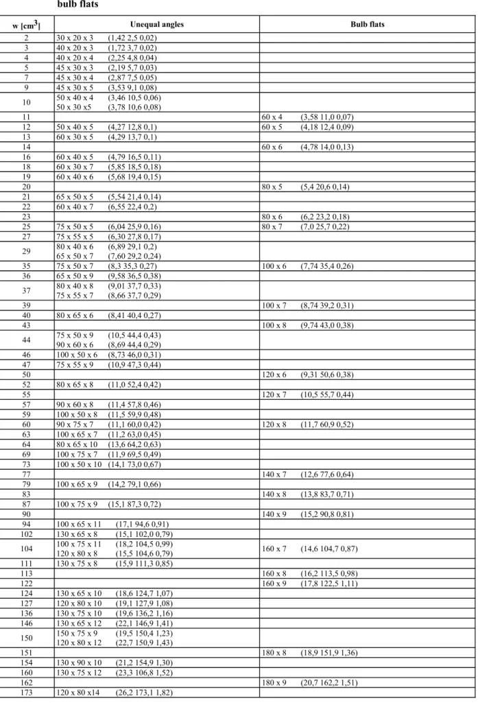
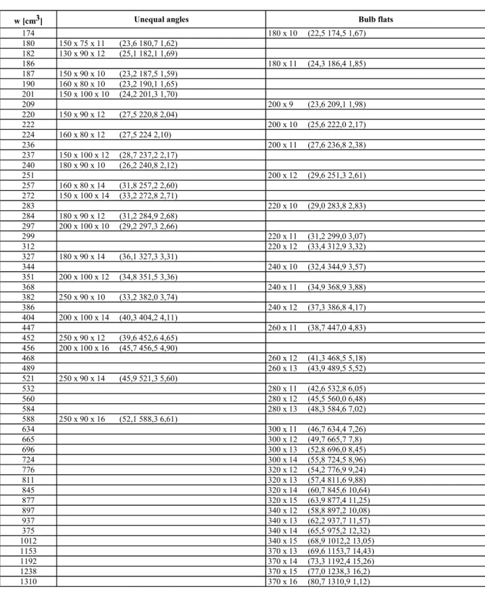
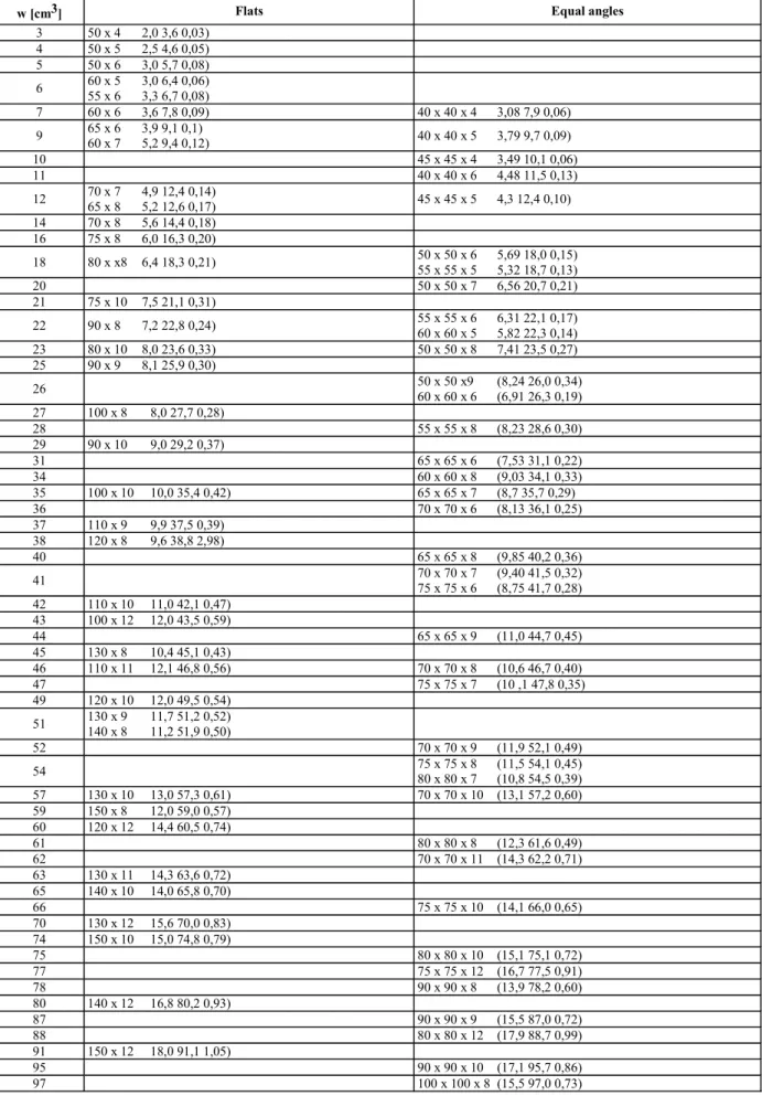
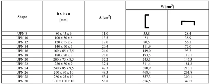
4.4 Sections
The main characteristics of sections currently used are
given in F.
4.5 Built sections 4.5.1 Geometric properties
The geometric properties of built sections as shown in Fig. 2.5 may be calculated as indicated in the follow-ing formulae. tp tf tw bf hw
Fig. 2.5 Dimensions of a built section
The shear sectional area of a built section with
at-tached plating is to be obtained [cm2] from the
follow-ing formula: w w sh h t A 100 ⋅ =
The section modulus of a built section with attached
plating of sectional area Aa [mm2] is to be obtained
[cm3] from the following formula:
I - Part 2 GL 2011
Section 2 Materials and Structure Design Principles Chapter 2
Page 2–5 B
2 w f f W W a f f W W a h t b t h A t b w 1 t h 1000 6000 A 2 ⎛ ⎞ ⎜ ⎟ ⋅ ⋅ ⋅ ⋅ − ⋅ = + ⋅ +⎜ ⋅ ⎟ ⎜ + ⎟ ⎜ ⎟ ⎝ ⎠
The distance from mid-plate thickness of face plate to neutral axis is to be obtained [cm] from the following formula:
(
)
(
)
W a W W a f f W W h A 0,5 t h v 10 A t b t h ⋅ + ⋅ ⋅ = ⋅ + ⋅ + ⋅The moment of inertia of a built section with attached
plating is to be obtained [cm4] from the following
formula:
I = w⋅v
These formulae are applicable provided that:
a f f A ≥t b⋅ w p h 10 t ≥ w f h 10 t ≥ 4.6 End connections
4.6.1 Continuous ordinary stiffeners
Where ordinary stiffeners are continuous through primary supporting members, they are to be connected to the web plating so as to ensure proper transmission of loads, e.g. by means of one of the connection de-tails shown in Fig. 2.6 to Fig. 2.9. In the case of high values for the design loads, additional stiffening is required.
Connection details other than those shown in Fig. 2.6 to Fig. 2.9 may be considered by GL on a case-by-case basis. In some case-by-cases, GL may require the details to be supported by direct calculations submitted for review.
Fig. 2.6 End connection of ordinary stiffener without collar plate
Fig. 2.7 End connection of ordinary stiffener Collar plate
Fig. 2.8 End connection of ordinary stiffener One large collar plate
Fig. 2.9 End connection of ordinary stiffener Two large collar plates
4.6.2 Intercostal ordinary stiffeners
Where ordinary stiffeners are cut at primary support-ing members, brackets are to be fitted to ensure the structural continuity. Their section modulus and their sectional area are to be not less than those of the ordi-nary stiffeners.
All brackets for which:
b
t > 60
l
lb = length [mm] of the free edge of the bracket
t = bracket net thickness [mm]
are to be flanged or stiffened by a welded face plate.
The sectional area [cm2] of the flange or the face plate
is to be not less than 0,01⋅lb.
The width of the face plate is to be not less than 10⋅t.
Chapter 2 Page 2–6
Section 2 Materials and Structure Design Principles I - Part 2
GL 2011 B
4.6.3 Bracketed ordinary stiffeners
4.6.3.1 For the scantlings of brackets the required section modulus of the section is decisive. Where sections of different section moduli are connected to each other, the scantlings of the brackets are generally governed by the smaller section.
4.6.3.2 The net thickness of brackets is not to be less than: 3 1 W t c k = ⋅
c = 1,2 for non-flanged brackets
= 0,95 for flanged brackets
k1 = material factor k for the section according A.
2.4 and 3.2
W = section modulus of smaller section [cm3]
tmin = 5,0 mm
tmax = web thickness of smaller section
4.6.3.3 Thearmlengthofbracketsisnottobelessthan:
3 2 t 1 W 46, 2 k c k = ⋅ ⋅ ⋅ l l = 100 mm ct = a t t
ta = "as built" thickness of bracket [mm]
≥ t according 4.7.2
W = see 4.7.2
k2 = material factor k for the bracket according to
A.2.4 and 3.2
The arm length l is the length of the welded
connec-tion.
Note
For deviating arm lengths, the thickness of brackets is to be estimated by direct calculations considering sufficient safety against buckling.
4.6.3.4 The throat thickness a of the welded
connec-tion is to be determined according to Section 8, A.4.8.
4.6.3.5 Where flanged brackets are used, the width of flange is to be determined according to the following formula:
W b 40
30
= + [mm]
b is not to be taken less than 50 mm and need not be taken greater than 90 mm.
4.6.4 Sniped ends of stiffeners
Stiffeners may be sniped at the ends if the thickness of the plating supported by the stiffeners is not less than:
(
)
e H p s 0,5 s t c R ⋅ ⋅ − ⋅ = ⋅ lp = stiffener design load [kN/m2] c = coefficient
= 15,8 for watertight bulkheads and for tank bulkheads
= 19,6 for all other components
5. Primary supporting members 5.1 Span of primary supporting members
The span of primary supporting members is to be determined in compliance with 4.2.
5.2 Width of attached plating 5.2.1 Girders
5.2.1.1 The effective breadth of plating em of frames and girders may be determined according to Table 2.7, considering the type of loading.
Special calculations may be required for determining the effective breadth of one-sided or non-symmetrical flanges.
5.2.1.2 The effective cross sectional area of plates is not to be less than the cross sectional area of the face plate.
5.2.1.3 The effective width of stiffeners and girders subjected to compressive stresses may be determined according to C.2.2, but is in no case to be taken greater than the effective breadth determined by 5.2.1.1.
Table 2.7 Effectivebreadthem offramesandgirders
l/e 0 1 2 3 4 5 6 7 ≥ 8
em1/e 0 0,36 0,64 0,82 0,91 0,96 0,98 1,00 1,0 em2/e 0 0,20 0,37 0,52 0,65 0,75 0,84 0,89 0,9 em1 isto beappliedwhere girdersareloadedby
uni-formlydistributedloadsorelsebynotlessthan6 equallyspacedsingleloads.
em2 is to be applied where girders are loaded by 3 or less single loads.
Intermediate values may be obtained by direct interpola-tion.
l = length between zero-points of bending moment curve, i.e. unsupported span in case of simply supported girders and 0,6 × unsupported span in case of constraint of both ends of girder
e = width of plating supported, measured from centre to centre of the adjacent unsupported fields
I - Part 2 GL 2011
Section 2 Materials and Structure Design Principles Chapter 2 Page 2–7
5.2.2 Cantilevers
Wherecantileversarefittedateveryframe,theeffective breadth of plating may be taken as the frame spacing. Wherecantileversarefittedatagreaterspacing,the ef-fective breadth of plating at the respective cross section may approximately be taken as the distance of the cross sectionfromthepointonwhichtheloadisacting, how-ever, not greater than the spacing of the cantilevers.
5.2.3 Corrugated bulkheads
The width of attached plating of corrugated bulkhead primary supporting members is to be determined as follows:
– when primary supporting members are parallel to the corrugations and are welded to the corru-gation flanges, the width of the attached plating is to be calculated in accordance with 5.2.2 and 5.2.3, and is to be taken not greater than the cor-rugation flange width
– when primary supporting members are perpen-dicular to the corrugations, the width of the at-tached plating is to be taken equal to the width of the primary supporting member face plate.
5.3 Geometric properties 5.3.1 Built sections
The geometric properties of primary supporting mem-bers(includingprimarysupportingmembersofdouble hullstructures,suchasdoublebottomfloorsand gird-ers) are generally determined in accordance with 4.5.1, reducing the web height hw by the depth of the cut-outs for the passage of the ordinary stiffeners, if any.
5.4 Bracketed end connections
5.4.1 Arm lengths of end brackets are to be equal, as far as practicable.
The height of end brackets is to be not less than that of the weakest primary supporting member.
5.4.2 The scantlings of end brackets are generally to be such that the section modulus of the primary supporting member with end brackets is not less than that of the primary supporting member at mid-span.
5.4.3 The bracket web thickness is to be not less than that of the weakest primary supporting member.
5.4.4 The face plate of end brackets is to have a width not less than the width of the primary support-ing member faceplates.
Moreover, the thickness of the face plate is to be not less than that of the bracket web.
5.4.5 In addition to the above requirements, the scantlings of end brackets are to comply with the applicable requirements given in Section 5, B. to E.
5.5 Bracketless end connections
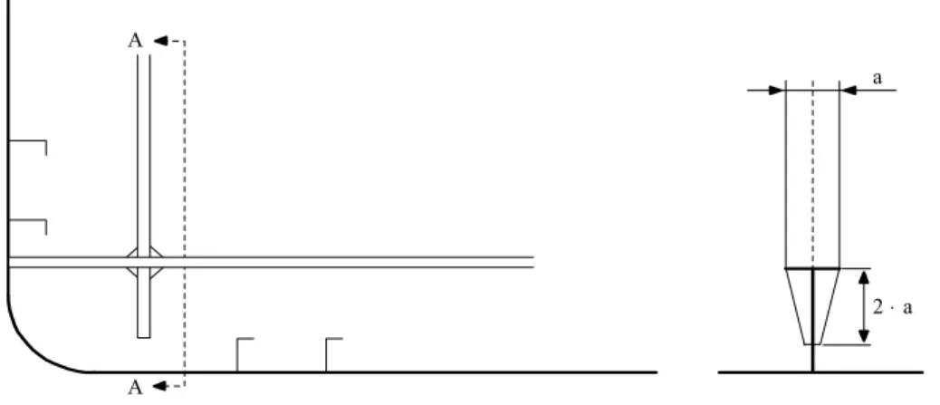
5.5.1 In the case of bracketless end connections between primary supporting members, the strength continuity is to be obtained as schematically shown in Fig. 2.10 or by any other method which GL may con-sider equivalent.
5.5.2 In general, the continuity of the face plates is to be ensured.
5.6 Cut-outs and holes
5.6.1 Cut-outs for the passage of ordinary stiffeners are to be as small as possible and well rounded with smooth edges.
In general, the depth of cut-outs is to be not greater than 50 % of the depth of the primary supporting member. Other cases are to be covered by calculations submitted to GL.
5.6.2 Openings may not be fitted in way of toes of end brackets.
2⋅a a A
A
Fig. 2.10 Connection of two primary supporting members Chapter 2
Page 2–8
Section 2 Materials and Structure Design Principles I - Part 2 GL 2011
5.7 Stiffening arrangement 5.7.1 General
Webs of primary supporting members are generally to be stiffened where the height [mm] is greater than 100 t, where t is the web thickness [mm] of the pri-mary supporting member.
In general, the web stiffeners of primary supporting members are to be spaced not more than 110 t.
5.7.2 Longitudinal framing system
In way of each longitudinal the transverses are to be stiffened. This stiffener is to extend between the longi-tudinal and the upper faceplate of the transverse, with-out any connection with that faceplate.
The stiffener is to be made of a flat, the width b and thickness t of which [mm] are not to be less than:
20 b w 3 = l 2 t w 3 = l
wlbeingthesectionmodulusofthelongitudinal[cm3].
However, on deck transverses, side shell transverses or longitudinal bulkhead transverses, stiffeners may be provided only every two longitudinal spacings.
GLmaywaivethisrulewherethetransverseisarolled
section or where it is otherwise covered by calculations. The sectional area of the connection of the transverse stiffener to the longitudinal and to the transverses is not to be less than the stiffener rule sectional area. 5.7.3 Tripping brackets (see Fig. 2.11) welded to the face plate are generally to be fitted:
– at intervals not exceeding 20 times the face plate
width
– at the toe of end brackets
– at rounded face plates
– in way of cross ties
– in way of concentrated loads
b
d
Fig. 2.11 Primary supporting member:
web stiffener in way of ordinary stiffener
Where the width of the symmetrical face plate is greater than 400 mm, backing brackets are to be fitted in way of the tripping brackets.
5.7.4 The arm length of tripping brackets is to be not less than the greater of the following values [m]:
d = 0,38 b⋅
= 0,85 b st
t
⋅ ⋅
b = height [m] of tripping brackets, shown in Fig.
2.11
st = spacing [m] of tripping brackets
t = thickness [mm] of tripping brackets.
5.7.5 The thickness of the tripping brackets is not to be less than the web thickness of the primary sup-porting member.
6. Hull scantling principle 6.1 Calculation point 6.1.1 General
The calculation point is to be considered with respect to the reference co-ordinate system defined in
Section 1, A.1.4.
6.1.2 Plating
The elementary plate panel is the smallest unstiffened part of plating. Unless otherwise specified, the loads are to be calculated:
– for longitudinal framing, at the lower edge of
the elementary plate panel or, in the case of horizontal plating, at the point of minimum y-value among those of the elementary plate panel considered
– for transverse framing, at the lower edge of the
strake
6.1.3 Ordinary stiffeners
Unless otherwise specified, the loads are to be calcu-lated at mid-span of the ordinary stiffener considered. 6.1.4 Primary supporting members
Unless otherwise specified, the loads are to be calcu-lated at mid-span of the primary supporting member considered.
6.2 Bracket coefficients 6.2.1 Ordinary stiffeners
These Rules apply to ordinary stiffeners without end brackets, with a bracket at one end or with two equal end brackets.
The bracket coefficients βband βs, of ordinary
stiffen-ers are to be obtained from Table 2.8. I - Part 2
GL 2011
Section 2 Materials and Structure Design Principles Chapter 2
Page 2–9 B
Table 2.8 Bracket coefficients
Brackets at ends βb βs
0 1 1
1 0,90 0,95
2 0,81 0,90
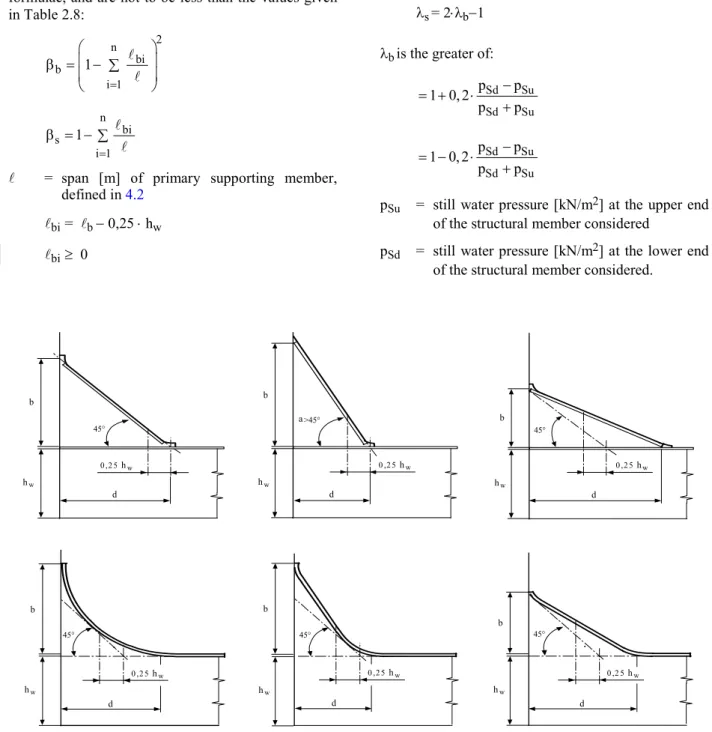
6.2.2 Primary supporting members
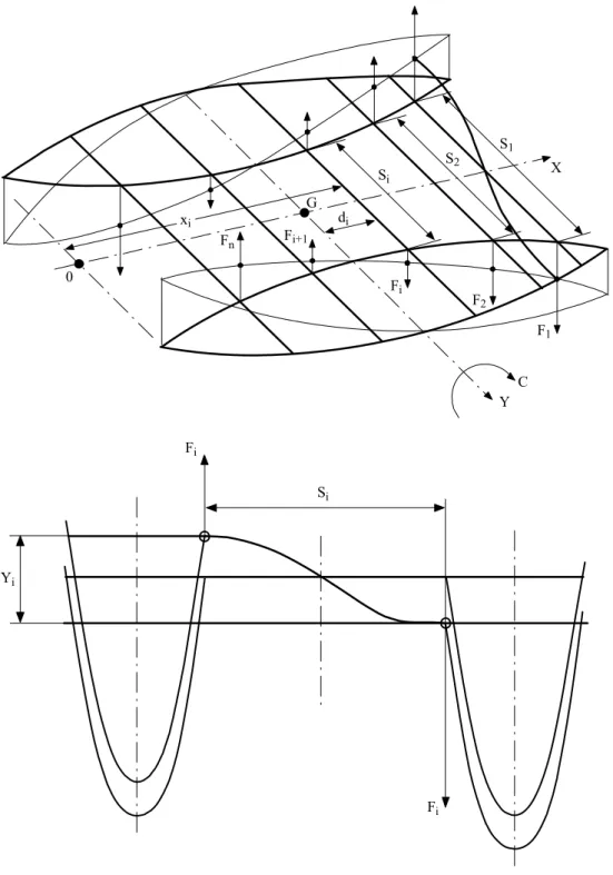
Conventional parameters of end brackets are given in Fig. 2.12. Special consideration is to be given to con-ditions different from those shown.
The bracket coefficients βband βs, of primary
support-ing members are to be determined ussupport-ing the followsupport-ing formulae, and are not to be less than the values given in Table 2.8: 2 n bi b i 1 1 = ⎛ ⎞ ⎜ ⎟ β = − ∑ ⎜ ⎟ ⎝ ⎠ l l n bi s i 1 1 = β = − ∑ l l
l = span [m] of primary supporting member,
defined in 4.2
lbi = lb − 0,25 ⋅ hw lbi ≥ 0
lb = MIN (d; b)
d, b = length [m] of brackets arms, defined in Fig. 2.12
hw = height [m] of the primary supporting member
(see Fig. 2.12)
n = number of end brackets
6.3 Coefficients for vertical structural mem-bers band s
The coefficients band Sto be used for the scantlings
of vertical structural members are to be determined as follows:
s= 2⋅b−1
bis the greater of:
Sd Su Sd Su p p 1 0, 2 p p − = + ⋅ + Sd Su Sd Su p p 1 0, 2 p p − = − ⋅ +
pSu = still water pressure [kN/m2] at the upper end
of the structural member considered
pSd = still water pressure [kN/m2] at the lower end
of the structural member considered.
45° a>45° 0 ,2 5hw 45° hw 45° 45° 45° d b hw b 0 ,2 5hw d 0 ,2 5hw d hw b 0 ,2 5hw d hw b hw b hw b 0 ,2 5hw d 0 ,2 5hw d
Fig. 2.12 Characteristics of primary supporting member brackets Chapter 2
Page 2–10
Section 2 Materials and Structure Design Principles I - Part 2
GL 2011 B
6.4 Plate panels 6.4.1 Thickness
The required thickness of plating subjected to lateral pressures may be reduced according to the aspect ratio and curvature of the panel considered, according to the formula:
t = t0⋅ca⋅cr
t0 = plating thickness [mm] as required in terms
of the lateral pressure ca = aspect ratio defined in 6.4.2
cr = coefficient of curvature defined in 6.4.3.
6.4.2 Aspect ratio
The aspect ratio of a plate panel is given by following formula:
2
a s s
c =1, 21 1 0,33⋅ + ⋅⎛ ⎞⎜ ⎟ −0,69⋅ ≤1
⎝ ⎠l l
s = length [m] of the shorter side of the plate
panel
l = length [m] of the longer side of the plate
panel
6.4.3 Curvature of plate panels
The coefficient of curvature of plate pane is given by the following formula:
r s
c 1 0,5 0,75
r
= − ⋅ ≥
r = radius of curvature [m]
7. Net strength characteristic calculation 7.1 General
7.1.1 The scantlings obtained by applying the crite-ria specified in these Rules are net scantlings, i.e. those which provide the strength characteristics re-quired to sustain the loads, excluding any addition for corrosion. Exceptions are the scantlings of:
– rudder structures and hull appendages in Section
7.
– massive pieces made of steel forgings, steel
castings or iron castings
7.1.2 The required strength characteristics are:
– thickness, for plating including that which
con-stitutes primary supporting members
– section modulus, shear sectional area, moments
of inertia and local thickness, for ordinary
stiff-eners and, as the case may be, primary support-ing members
– section modulus, moments of inertia and single
moment for the hull girder
7.1.3 The vessel is to be built at least with the gross scantlings obtained by reversing the procedure de-scribed in 7.2.
7.2 Designer’s proposal based on gross scant-lings
7.2.1 General criteria
If the designer provides the gross scantlings of each structural element, the structural checks are to be carried out on the basis of the net strength characteris-tics, derived as specified in 7.2.2 to 7.2.5.
7.2.2 Plating
The net thickness is to be obtained by deducting the
corrosion addition tCfrom the gross thickness.
7.2.3 Ordinary stiffeners
The net transverse section is to be obtained by
deduct-ing the corrosion addition tCfrom the gross thickness
of the elements which constitute the stiffener profile. The net strength characteristics are to be calculated for the net transverse section. As an alternative, the net section modulus may be obtained from the following formula:
w = wG⋅(1−α⋅tC)−β⋅tC
wG = stiffener gross section modulus [cm3]
α, β = coefficients defined in Table 2.9.
Table 2.9 Coefficients α and β
Type of ordinary stiffeners α β Flat bars – wG > 17 cm3 0,066 1,6 Flanged profiles – wG > 17 cm3 0,101 1,6 – wG ≤ 200 cm3 0,070 0,4 Bulb profiles:
– wG > 200 cm3 0,035 7,4
7.2.4 Primary supporting members
The net transverse section is to be obtained by
deduct-ing the corrosion addition tCfrom the gross thickness
of the elements which constitute the primary support-ing members.
The net strength characteristics are to be calculated for the net transverse section.
7.2.5 Hull girder
For the hull girder, the net hull transverse sections are to be considered as being constituted by plating and stiffeners having net scantlings calculated on the basis
ofthecorrosionadditionstC,accordingto7.2.2to7.2.4.
I - Part 2
7.3 Designer’sproposalbasedonnetscantlings 7.3.1 Net strength characteristics and corrosion
additions
If the designer provides the net scantlings of each structural element, the structural checks are to be carried out on the basis of the proposed net strength characteristics.
The designer is also to provide the corrosion additions or the gross scantlings of each structural element. The proposed corrosion additions are to be not less than the values specified in 8.
7.3.2 Hull girder net strength characteristic calculation
For the hull girder, the net hull girder transverse sec-tions are to be considered as being constituted by plating and stiffeners having the net scantlings pro-posed by the designer.
8. Corrosion additions 8.1 Values of corrosion additions 8.1.1 General
Thevaluesofthecorrosionadditionsspecifiedinthis
Articlearetobeappliedinrelationtotherelevant
corro-sionprotectionmeasuresprescribedin Section8,B.1.
The designer may define values of corrosion additions greater than those specified in 8.1.2.
8.1.2 Corrosion additions for steel other than stainless steel
The corrosion addition for each of the two sides of a
structuralmember,tC1 ortC2,isspecifiedinTable2.10.
– for plating with a net thickness greater than 8
mm, the total corrosion addition tC [mm] for
both sides of the structural member is obtained by the following formula:
tC = tC1 + tC2
– for plating with a net thickness less than or
equal to 8 mm, the smallest of the following values:
– 25 % of the net thickness of the plating
– tC = tC1 + tC2
For an internal member within a given compartment,
the total corrosion addition tC is obtained from the
following formula: tC = 2⋅tC1
When a structural element is affected by more than one value of corrosion addition (e.g. plate in a dry bulk cargo hold extending in the double bottom), the scantling criteria are generally to be applied consider-ing the severest value of corrosion addition applicable to the member.
8.1.3 Corrosion additions for stainless steel and aluminium alloys
For structural members made of stainless steel or aluminium alloys, the corrosion addition is to be taken
equal to 0,25 mm, for one side exposure (tC1= tC2=
0,25 mm)
Table 2.10 Corrosion additions [mm] for one side exposure (tc1 or tc2)
Compartment type General 1
Ballast tank 1,00 Plating of horizontal surfaces 0,75 Plating of non-horizontal surfaces 0,50 Cargo tank and
fuel oil tank Ordinary stiffeners and primary supporting members
0,50
General 1,00 Inner bottom plating
Side plating for single hull vessel
Inner side plating for double hull vessel Transverse bulkhead plating 1,75 Dry bulk cargo hold Frames, ordinary stiffeners and primary
supporting members 0,50
Hopper well of dredging vessels 2,00
Accommodation space 0,00
Compartments and areas other than
those mentioned above 0,50
1 General: corrosion additions are applicable to all members of the considered item.
C. Proof of Buckling Strength
The calculation method is based on DIN standard 18800.
1. Definitions
a = length of single or partial plate field [mm]
b = breadth of single plate field [mm]
α = aspect ratio of single plate field
= a / b
n = number of single plate field breadths within
the partial or total plate field
t = nominal plate thickness [mm]
= ta – tC [mm]
ta = plate thickness as built [mm]
Chapter 2
tC = corrosion addition according to K. [mm]
σx = membrane stress in x-direction [N/mm2]
σy = membrane stress in y-direction [N/mm2]
τ = shear stress in the x-y plane [N/mm2]
Compressive and shear stresses are to be taken posi-tive, tension stresses are to be taken negative.
y a am bm y x b b
single field partial field
n·b
long. stiffener
transverse stiffener
longitudinal : stiffener in the direction of the length a transverse : stiffener in the direction of the breath b Fig. 2.13 Definitionofplatefieldssubjectto
buckling
Note
If the stresses in the x- and y-direction already contain the Poisson effect, the following modified stress values may be used:
Both stressesσx* undσy* are to be compressive stres-ses,in order to apply the stress reduction according to the following formulae:
(
)
(
)
* * * * 0,91 0,91 = − ⋅ = − ⋅ x x y y y x 0,3 0,3 σ σ σ σ σ σσx*, σy* = stresses containing the Poisson effect Wherecompressivestressfulfilstheconditionσy*<0,3⋅σx*, thenσy=0andσx=σx*.
Wherecompressivestressfulfilstheconditionσx*<0,3⋅σy*, thenσx = 0andσy= σy*.
When at leastσx* orσy* is tension stress,thenσx = σx* andσy= σy*.
ψ = edge stress ratio according to Table 2.12
F1 = correctionfactorforboundaryconditionat
thelong.stiffenersaccordingtoTable2.11
Table 2.11 Correction factor F1
1,0 for stiffeners sniped at both ends
Guidance values where both endsare effectively
connected toadjacent structures * :
1,05 for flat bars
1,10 for bulb sections
1,20 for angle and tee-sections
1,30 for girders of high rigidity
(e.g. bottom transverses)
* Exact values may be determined by direc t calcula tions.
σe = reference stress = 2 2 t 0,9 E [N / mm ] b ⎛ ⎞ ⋅ ⎜ ⎟ ⎝ ⎠ E = Young’s modulus = 2,06 10 N/mm⋅ 5 2 for steel
= 0,69 10 N / mm⋅ 5 2 for aluminium alloys
ReH = nominal yield point [N/mm2] for hull
struc-tural steels according to A.2.
= 0,2 % proof stress [N/mm2] for aluminium
alloys
S = safety factor
= 1,1 in general
= 1,2 for structures which are exclusively
exposed to local loads
= 1,05 for combinations of statistically inde-pendent loads
Forconstructionsofaluminiumalloys,thesafety
fac-tors are to be increased in each case by 0,1.
λ = reference degree of slenderness
= eH
e
R
K ⋅ σ
K = buckling factor according to Tables 2.12 and
2.13
In general, the ratio of plate field breadth to plate thickness shall not exceed b/t = 100.
I - Part 2
2. Proof of single plate fields
2.1 Proof is to be provided that the following
condition is complied with for the single plate field a ⋅ b: e2 e1 2 y x y x 2 x eH y eH eH e3 eH S S S B R R R 3 S 1,0 R τ ⎛ σ ⋅ ⎞ ⎛σ ⋅ σ ⋅ ⎞ ⎛ σ ⋅ ⎞ ⎜ ⎟ ⎜ ⎟ + − ⎜ ⎟ ⎜κ ⋅ ⎟ ⎜κ ⋅ ⎟ ⎜ ⎟ ⎝ ⎠ ⎝ ⎠ ⎝ ⎠ ⎛ τ ⋅ ⋅ ⎞ ⎜ ⎟ + ⎜ ⎟ ≤ κ ⋅ ⎝ ⎠
Each term of the above condition shall not exceed 1,0.
The reduction factors κx, κy and κτ are given in Table
2.12 and/or 2.13.
Where σx≤ 0 (tension stress), κx = 1,0.
Where σy≤ 0 (tension stress), κy = 1,0.
The exponents e1, e2 and e3 as well as the factor B are
calculated or set respectively:
plate field Exponents e1 – e3
and factor B plane curved
e1 1+ κ4x 1,25 e2 1+ κ4y 1,25 e3 1+ κ ⋅ κ ⋅ κx y 2τ 2,0 B σx and σy positive (compression stress) 5 x y (κ ⋅ κ ) 0 B σx or σy negative (tension stress) 1 ––
2.2 Effective width of plating
The effective width of plating may be determined by the following formulae:
m x
b = κ ⋅ b for longitudinal stiffeners
m y
a = κ ⋅ a for transverse stiffeners see also Fig. 2.13.
The effective width of plating is not to be taken greater thantheeffectivebreadthobtainedfromB.4.3andB.5.2.
Chapter 2
Table 2.12 Plane plate fields 1 l K = F1 1 + 2 K = F1 1 + (13,9 10 y) K = F1 1 + (5,87 + 1,87 a2 + 10 y) K = F1 2 5,975 K = F1 2 3,9675 + 0,5375 4 + 1,87 2,1 (1+y) 1,1 y a2 8,6 a2 1 - y a 1 - y a y a2
Load case Edge stress
ratio y Buckling factor K Reduction factor k
1 ³y³ 0 0 > y > 1 y £ 1 a > 1 1 ³y ³ 0 0 > y > 1 y £ 1 a³ 1 1 £ a £ 1,5 a > 1,5 1 £a£ a > 1 2 a · b y·sx y·sx sx sx t b K = K = 7,63 y (6,26 10 y) K = (1 y)2 · 5,975 8,4 y + 1,1 1 a2 1 a2 1 a2 3 (1-y) 4 1 - y a kx= 1 for l £lc kx= c - for l > lc c = (1,25 - 0,12y) £ 1,25 lc= 1 + Ö 1 -0,22 l2 sy b y·sy y·sy sy t a · b 2,1 (1+y) 1,1 2 2 2l c (T+Ö T2 - 4 ) H = l - ³ R ky= c -1l R+F 2 (H-R) l2 c = (1,25 - 0,12y) £ 1,25 R =l 1- for lc l < lc R = 0,22 for l³lc lp= l2- 0,5 1 £ lp 2£ 3 c1= 1 for sy due to direct loads
c1= 0 for sy due to bending in extreme load cases (e. g. w. t. bulkheads) lc= 1 + c2 Ö 1-0,88c T = l + +1514l 13 2,1 (y+1,1) 3 (1-y) 4 c 2 0,88c lp2 F = 1 - c1 ³ 0 K 0,91-1 c1= 1 - ³ 0 for sy due to bending (in general)
F1 a 3 K = K = 4 0,425 + (1 + y) 5 · y (1 3,42 y) 1 a2 1 ³y³ 0 0 > y³ 1 a > 0 a > 0 4 1 ³y³ 1 a · b sx y·sx y·sx sx t b 4 (0,425 + 1/a2) 3 y + 1 K = 0,425 + 1 a2 a · b sx y·sx y·sx sx t b kx = 1 for l£ 0,7 kx = for 1 l > 0,7 l2 + 0,51 3 - y 2 2 Aspect ratio a I - Part 2
Table 2.12 Plane plate fields (continued)
Load case Edge stress
ratio y Aspect ratioa Buckling factor K Reduction factor k
r = (1 - )(1 - ) with £ 0,7 and £ 0,7 b t t t t a · b t da db t t t t a · b t b a · b t sx sx b K = 1,28 K = + 0,56 + 0,13 1 a2 a2 5 a³ 1 0 < a < 1 a ³ 1,64 a < 1,64 Kt = 5,34 + Kt = 4 + 4 a2 5,34 a2 6 7 K = Kt · 3 da a K = K' × r
K' = K according to load case 5 r = Reduction factor db b da a dbb kt = 1 for l£ 0,84 kt = for 0,84 l > 0,84 l a· b t sx sx b a · b t b sx sx a · b t sx sx b K = 6,97 K = + 2,5 + 5 1 a2 a2 K = 4 K = 4 + 4 2,74 K = + 2,07 + 0,67 4 a2 a2 4 a 3 K = 6,97 K = 6,97 + 4 3,1 K = + 2,07 + 4 4 a2 a2 4 a 3 a ³ a < 2 3 2 3 a ³ 4 4 > a > 1 a £ 1 a ³ 4 4 > a > 1 a £ 1 8 9 10 for l > 0,83 kx = 1,13 -1l 0,22 l2 kx = 1 for l£ 0,83
plate edge free
plate edge simply supported plate edge clamped Explanations for boundary conditions
kx = 1 for l£ 0,7 kx = for l > 0,7 1 l2 + 0,51 Chapter 2
Table 2.13 Curved plate field R/t ≤ 2500 1
Load case Aspect ratio
b / R Buckling factor K Reduction factor k
1a £ 1,63 b R R t R t > 1,63 b R kx = 1 2 for l£ 0,4 kx = 1,274 0,686 l for 0,4 < l£ 1,2 kx = for l> 1,2 0,65 l2 ky = 1 2 for l £ 0,25 ky = 1,233 0,933 l for 0,25 < l £ 1 ky = 0,3 / l3 for 1 < l £ 1,5 ky = 0,2 / l2 for l > 1,5 R t sy b sy £ 0,5 b R > 0,5 b R R t R t K = 1 + K = 0,267 3 ³ 0,4 2 3 b2 R · t b2 R · t b R t R b2 R · t sx R t b sx kt = 1 for l £ 0,4 kt = 1,274 0,686 l for 0,4 < l £ 1,2 kt = for l > 1,2 0,65 l2 as in load case 1a Kt = 0,28 b2 R R · t R t £ 8,7 b R R t > 8,7 b R Kt = 28,3 + 0,67 · b3 0,5 R1,5 · t1,5 R t b t R t b pe sx = pe · R t with R t sx b sx 1b K = + 3 (R· t)0,175 b0,35 b R · t K = 0,3 + 2,25 b2 2 R2 R2 b · t 2 3 £ b R R t > b R R t K = + 0,3R· t b 0,6 · b R · t R· t b2 K = 0,3 + 0,291 R2 2 b · t b2 R2 4
plate edge free
plate edge simply supported plate edge clamped Explanations for boundary conditions:
K = Kt × 3
pe = external pressure in [N/mm2]
1 For curved plate fields with a very large radius the k-value need not to be taken less than one derived for the expanded plane field. 2 For curved single fields. e.g. the bilge strake, which are located within plane partial or total fields, the reduction factor k may taken as follow:
Load case 1b: kx = 0,8/l2£ 1,0: load case 2: ky = 0,65/l2£ 1,0 I - Part 2
Note
The effective width e'm of stiffened flange plates of girders may be determined as follows:
Stiffening parallel to web of girder:
em e bm bm b b b b em' y sx,em (y) sx,em '(y) b < em e'm = n ⋅ bm
n = integer number of the stiffener spacing b inside the effective breadthem
= int ⎛⎜ ⎞⎟
⎝ ⎠
m e
b
Stiffening perpendicular to web of girder:
em am e e a em' sx1 sx (y) y sx2 a ≥ em e'm = n ⋅ am < e m n = 2,7 ⋅ em ≤ 1 a
e = width of plating supported according to B.4.3 and B.5.2
For b ≥ em or a < em respectively, b and a have to be exchanged.
am and bm for flange plates are in general to be de-termined for ψ = 1.
Stress distribution between two girders:
( )
2(
)
⎧ ⎡ ⎤⎫ = ⋅⎨ ⎢ ⋅ ⎥⎬ ⎣ ⎦ ⎩ ⎭ x y x1 1 ey 3 c1 4 c 2ey 1 c1 2 c2 σ σ − + − − + − c1 = 2 1 x 1 x 0 c 1 σ ≤ ≤ σ c2 = 1,5e ⋅(
e"m1+em2")
−0,5 e" m1 = m1 m1 e' e e"m2 = m2 m2 e' eσx1, σx2 = normal stresses in flange plates of adja-cent girder 1 and 2 with spacing e y = distance of considered location from
girder 1
Scantlings of plates and stiffeners are in general to be determined according to the maximum stresses σx(y) at girder webs and stiffeners respectively. For stiffen-ers under compression arranged parallel to the girder web with spacing b, no lesser value than 0,25 ⋅ ReH shall be inserted for σx(y=b).
Shear stress distribution in the flange plates may be assumed linearly.
2.3 Webs and flanges
For non-stiffened webs and flanges of sections and girders, proof of sufficient buckling strength is to be provided as for single plate fields according to 2.1.
Chapter 2
![Table 3.10 Dry unit cargoes – Inertial forces Vessel condition Inertial force F W [kN] 1 Upright (positive heave motion) F W,X = m C ⋅a X1 in x directionFW,Z = mC⋅aZ1 in z direction Inclined](https://thumb-us.123doks.com/thumbv2/123dok_us/1800345.2758194/56.892.459.795.656.840/inertial-condition-inertial-upright-positive-directionfw-direction-inclined.webp)