University of Windsor University of Windsor
Scholarship at UWindsor
Scholarship at UWindsor
Electronic Theses and Dissertations Theses, Dissertations, and Major Papers
2016
A New Frontier Based Approach for Multi-Robot Coverage in
A New Frontier Based Approach for Multi-Robot Coverage in
Unknown Environments
Unknown Environments
Sushil Parti
University of Windsor
Follow this and additional works at: https://scholar.uwindsor.ca/etd
Recommended Citation Recommended Citation
Parti, Sushil, "A New Frontier Based Approach for Multi-Robot Coverage in Unknown Environments" (2016). Electronic Theses and Dissertations. 5758.
https://scholar.uwindsor.ca/etd/5758
This online database contains the full-text of PhD dissertations and Masters’ theses of University of Windsor students from 1954 forward. These documents are made available for personal study and research purposes only, in accordance with the Canadian Copyright Act and the Creative Commons license—CC BY-NC-ND (Attribution, Non-Commercial, No Derivative Works). Under this license, works must always be attributed to the copyright holder (original author), cannot be used for any commercial purposes, and may not be altered. Any other use would require the permission of the copyright holder. Students may inquire about withdrawing their dissertation and/or thesis from this database. For additional inquiries, please contact the repository administrator via email
A New Frontier Based Approach for Multi-Robot Coverage in Unknown
Environments
by
Sushil Parti
A Thesis
Submitted to the Faculty of Graduate Studies
through the School of Computer Science
in Partial Fulfillment of the Requirements for
the Degree of Master of Science at the
University of Windsor
Windsor, Ontario, Canada
2016
A New Frontier Based Approach for Multi-Robot Coverage in Unknown
Environments
by
Sushil Parti
APPROVED BY:
______________________________________________ Dr. Huapeng Wu
Department of Electrical and Computer Engineering
______________________________________________ Dr. Imran Ahmad
School of Computer Science
______________________________________________
Dr. Dan Wu, Advisor School of Computer Science
iii
DECLARATION OF ORIGINALITY
I hereby certify that I am the sole author of this thesis and that no part of this thesis has
been published or submitted for publication.
I certify that, to the best of my knowledge, my thesis does not infringe upon anyone’s
copyright nor violate any proprietary rights and that any ideas, techniques, quotations, or any
other material from the work of other people included in my thesis, published or otherwise,
are fully acknowledged in accordance with the standard referencing practices. Furthermore,
to the extent that I have included copyrighted material that surpasses the bounds of fair
dealing within the meaning of the Canada Copyright Act, I certify that I have obtained a
written permission from the copyright owner(s) to include such material(s) in my thesis and
have included copies of such copyright clearances to my appendix.
I declare that this is a true copy of my thesis, including any final revisions, as approved by
my thesis committee and the Graduate Studies office, and that this thesis has not been
iv
ABSTRACT
With the emergence of technology in our daily lives, robots are being increasingly used for
coverage tasks which were earlier considered too dangerous or monotonous to be performed
by humans such as interplanetary exploration and search & rescue. Out of all the multi-robot
coverage approaches, the frontier based approach is one of the most widely used. Most of
the coverage approaches developed so far, face the issue of frontier duplication and require
access to the maps of the environment prior to coverage. In this work, we have developed a
new frontier based approach for multi-robot coverage in unknown environments. This new
approach is scalable to multiple robots and does not require prior access to the maps. This
approach also uses a new frontier allocation and robot coordination algorithm, which
v
DEDICATION
To my loving family:
Mother: Rama Parti
Father: Raj Kumar Parti
vi
ACKNOWLEDGEMENTS
This dissertation would not have been possible without the guidance, help and support of
several individuals who contributed and extended their valuable assistance in the completion
of this work.
First and foremost, I would like to thank my supervisor Dr. Dan Wu for his guidance and
support throughout my graduate studies. I would like to thank him for being so friendly and
for motivating me through our conversations. One simply could not wish for a better
supervisor.
I would like to thank members of my thesis committee, Dr. Imran Ahmad, and Dr.
Huapeng Wu for their valuable time, suggestions and constructive comments. I would also
like to thank Mrs. Karen Bourdeau, for helping me with all the administrative duties with
this thesis.
I would like to thank the open source community, especially the ROS and Stage
communities for volunteering their valuable time to create open source tools and tutorials.
Without their support, this work could not have completed in a timely and effective manner.
Finally, I would like to thank my family and friends for all their support and motivation in
vii
TABLE OF CONTENTS
DECLARATION OF ORIGINALITY iii
ABSTRACT iv
DEDICATION v
ACKNOWLEDGEMENTS vi
LIST OF TABLES x
LIST OF FIGURES xi
LIST OF ABBREVIATIONS/SYMBOLS xiv
INTRODUCTION 1
1.1 Motivation 3
1.2 Problem Statement 4
1.3 Thesis Organization 5
LITERATURE REVIEW 6
2.1 Exploration and Coverage 6
2.2 Navigation and Path Planning 7
2.2.1 Mapping 9
2.2.2 Localization 13
2.2.3 Path Planning 16
2.3 Multi-Robot Coverage 17
2.3.1 Communication Network 18
2.3.2 Coordination Strategy 18
2.3.3 Path Planning 19
2.4 Coverage Strategies 19
2.4.1 Traditional Coverage Strategies 20
2.4.2 Cellular Decomposition 21
2.4.3 Multi-Robot Coverage Strategies 23
2.5 Summary 27
ROBOT OPERATING SYSTEM (ROS) 28
3.1 Overview 28
3.2 Architecture 29
3.2.1 Filesystem Level 29
viii
3.2.3 Community Level 33
3.3 ROS Development Tools 34
3.3.1 rviz 34
3.3.2 rqt_console 35
3.3.3 rqt_graph 35
3.4 Important ROS Stacks 37
3.4.1 Navigation Stack 37
3.4.2 Actionlib Stack 39
3.5 Stage 39
PROPOSED REMEMBER-ALL FRONTIER BASED MULTI-ROBOT COVERAGE APPROACH 42
4.1 Background 42
4.2 Assumptions 43
4.3 Proposed Coverage Approach 44
4.3.1 Localization and Mapping 46
4.3.2 Map Merging 46
4.3.3 Update Occupancy Grid 47
4.3.4 Identify Frontiers 48
4.3.5 Allocate Frontiers 48
4.3.6 Navigate Robots 55
4.4 Proposed “Remember-All” Frontier Allocation Strategy 55
4.5 Proposed Communication Policy 63
4.6 Proposed Coordination Strategy 64
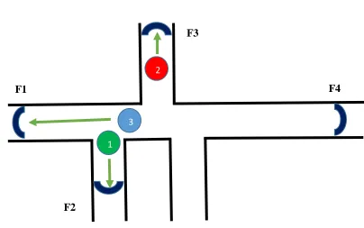
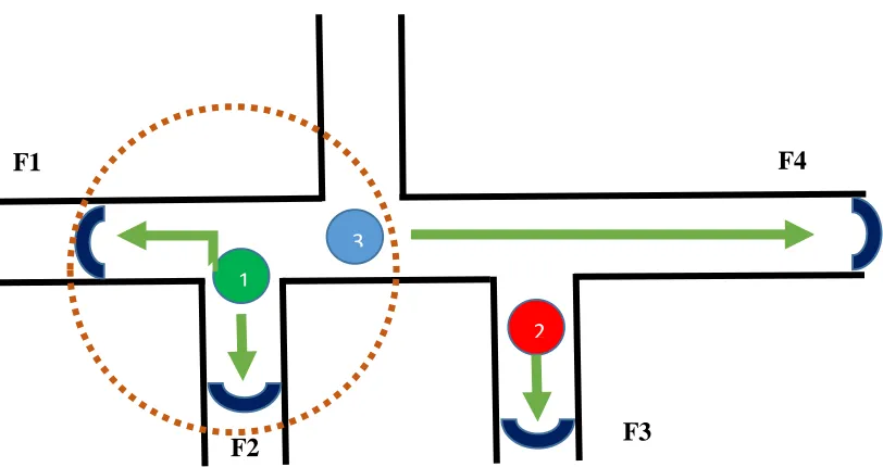
4.6.1 Proposed Buddy Approach 65
4.7 Comparison of Frontier Allocation Strategies 66
4.7.1 Comparison with the Enhanced Frontier Based Approach 68
EXPERIMENTS AND RESULTS 70
5.1 Experimental Setup 70
5.2 Coverage Results 71
5.2.1 Coverage Results for Two-Robot Systems 73
5.2.2 Coverage Results for Three Robot Systems 80
5.2.3 Coverage Results for Two Robot System (with Distant Starting Locations) 87
5.3 Summary 95
ix
6.1 Conclusion 96
6.2 Future Work 97
BIBLIOGRAPHY 99
APPENDICES 106
Appendix A: RESULT DATA 106
x
LIST OF TABLES
4.1 Cost Matrix 53
4.2 Position Matrix 53
5.1 Comparison of Coverage Strategies for the Hallway map 74
5.2 Comparison of Coverage Strategies for the Asymmetric room map 76
5.3 Comparison of Coverage Strategies for the Office map 79
5.4 Comparison of Coverage Strategies for the Hallway map (three robots) 81
5.5 Comparison of Coverage Strategies for the Asymmetric map (three robots) 84
5.6 Comparison of Coverage Strategies for the Hallway map (three robots) 86
5.7 Comparison of Coverage Strategies for the Asymmetric room map (distant robots) 88
5.8 Comparison of Coverage Strategies for the Office map (distant robots) 91
xi
LIST OF FIGURES
2.1 Processes required to solve challenges associated with robotic coverage [26] 8
2.2 Feature-based map of a sample environment [45] 10
2.3 Construction of a Topographical map [46] 10
2.4 Occupancy grid map of an environment [29] 12
2.5 Basic idea of robot localization in a sample environment [6] 14
2.6 Occupancy Grid [35] 22
2.7 Semi-approximate cellular decomposition [48] 22
2.8 Trapezoidal Exact Cellular Decomposition [36] 23
2.9 Frontier Detection Process [38] 26
3.1 Architecture of ROS Filesystem Level [40] 30
3.2 Sample ROS Message [49] 31
3.3 Architecture of ROS Computation Graph Level [40] 32
3.4 Environment visualization through rviz 34
3.5 rqt_console displaying messages 35
3.6 ROS computation graph 36
3.7 Organization of Navigation Stacks [40] 38
3.8 Client Server Model in actionlib Stack [61] 39
3.9 Multi-robot simulation in Stage 40
3.10 Sample world file 41
4.1 Proposed approach for multi-robot coverage in unknown environments 45
xii
4.3 Greedy Based frontier allocation strategy 51
4.4 Rank Based frontier allocation strategy 53
4.5 Threshold Based frontier allocation strategy 54
4.6 Proposed Remember-All Based frontier allocation strategy 57
4.7 Individual lists maintained by each robot for unallocated frontiers 57
4.8 Explored frontiers list of each robot at this step 58
4.9 Common pools of frontiers for each robot 60
4.10 Proposed Frontier Allocation Strategy (Case 1) 60
4.11 Proposed Frontier Allocation Strategy (Case 2) 61
4.12 ‘identified _frontiers’ list for all the three robots 62
5.1 Custom-built maps for the coverage experiments 71
5.2 Graph of robot coverage run-time in the hallway map 74
5.3 Graph of percentage of frontier coverage by individual robots in the hallway map 75
5.4 Graph of robot coverage run-time in the asymmetric room map 77
5.5 Average frontier coverage by individual robots in the asymmetric hall map 78
5.6 Graph of average run-time for robot coverage in the office map 80
5.7 Average frontier coverage by individual robots in the office map 80
5.8 Graph of robot coverage run-time in the hallway map 82
5.9 Average frontier coverage by individual robots in the hallway map 83
5.10 Graph of average run-time for robot coverage in the asymmetric room map 84
5.11 Average frontier coverage by individual robots in the asymmetric room map 85
5.12 Graph of individual robot run-time in the office map 86
5.13 Average frontier coverage by individual robots in the office map 87
xiii
5.15 Average frontier coverage by individual robots in the office map 90
5.16 Graph of robot run-time comparison in the asymmetric room map 91
5.17 Average frontier coverage by individual robots in the asymmetric room map 92
5.18 Graph of robot run-time comparison in the office map 94
xiv
LIST OF ABBREVIATIONS/SYMBOLS
AMCL
Adaptive Monte-Carlo Localization
CFOD
Closest Frontier Obstacle Distance
CMU
Carnegie Mellon University
EKF
Extended Kalman Filters
GUI
Graphical User Interface
LOS
Line of Sight
MRDS
Microsoft Robotics Developer Studio
NASA
National Aeronautics and Space Administration
OpenGL
Open Graphics Library
ROS
Robot Operating System
R.U.R
Rossum´s Universal Robots
RVIZ
Robot Visualization Tool
SLAM
Simultaneous Localization and Mapping
SAIL
Stanford Artificial Intelligence Laboratory
TCP
Transmission Control Protocol
1
Chapter 1
INTRODUCTION
The field of robotics has very much evolved far since 1921 when the term robot was
introduced in the play R.U.R by the Czech writer, Karel Capek [1]. Since then, robots have
been slowly but steadily moved from the realm of science fiction to reality. One of the major
fields of robotics research is using robots for exploration of areas which are inaccessible to
or dangerous for humans or for activities which are considered too monotonous for humans
[6].
After the Fukushima disaster in 2011 in Japan, robots were used to explore the nuclear plant
as any operation by humans would have been dangerous due to high radiation levels. The
robots provided useful data about the temperature and radiation levels inside the reactor
buildings. NASA also uses robots such as Curiosity and Opportunity to explore the surface
of Mars. Other applications include search and rescue [2], floor cleaning [3], ocean floor
mapping [4], and battlefield reconnaissance [5].
Robots can be categorized into two major categories: remote controlled robots and
autonomous robots. Remote controlled robots do not have the ability to analyze their
surroundings and then take decisions on their own. They always require humans to provide
them with continuous instructions. In contrast to them, autonomous robots are capable of
performing their tasks without human intervention. Autonomous robots sense their
environments, analyze the data and then respond back. The major advantage of autonomous
robots over remote controlled ones is that they do not have to spend a lot of time and
energy asking humans what to do and then wait for the response, and this results in benefits
2
The main focus of this work would be on using autonomous robots. Most of the
applications discussed so far require the robot to maximize the area covered in the
environment. All of these applications are derivatives of the coverage problem, which is a
subset of robot exploration [12]. The coverage problem is related to the “covering salesman
problem,” where the goal is to find the shortest length path covering all the given nodes [8].
Robotics literature is filled with numerous exploration approaches [9, 10, 11, 12, 13], with a
focus on using multiple robots to explore known environments.
Using multiple robots instead of one provides multiple benefits, such as the following [14]:
Improved Performance: multiple robots working in parallel are usually able to
complete a task faster than a single robot.
Increased Fault tolerance: using multiple robots increases the redundancy of the
overall system, so that even if one robot fails, others are still able to finish the task.
Efficient Localization: multiple robots exchange information about their position
leading to more efficient localization.
But, these advantages come with several issues which arise due to the use of multiple robots.
To overcome these problems, the system requires the following [15, 16]:
A dedicated communication network for inter-robot coordination.
Coordination strategy, so that robots cooperate, rather than compete with each
other.
Increased budget due to extra hardware costs.
The environments covered by the robots can be categorized into two categories: known
3
which maps are already available to the robots, but unfortunately, it is not practical to have
precise and updated maps for every case. This is especially true in the case of applications to
search and rescue, where every second of delay can cause the loss of human lives, and time
taken to create a map can be fateful. Robots working in such applications should have the
ability to work in unknown environments and perform coverage in them. Coverage of
unknown environments requires [6]:
Simultaneous Localization and Mapping (SLAM) modules for individual robots.
Map Merging module algorithms to create a global map from individual maps of
each robot.
Due to the nature of applications in which robot coverage is employed, time taken to cover
the whole environment is the most important evaluation criterion. Another key evaluation
criterion needed to measure the performance of robot coverage is the amount of overlap in
the robots’ coverage. In an ideal scenario, there should be no overlap in the area covered by
all the individual robots. But in real life, while performing their individual tasks, robots can
overlap areas already explored by other robots. In our proposed approach, the main aim is to
minimize the time taken by the robots as well as their overlap during area coverage.
1.1 Motivation
As robots are being increasingly used for a variety of applications, the robotic hardware is
changing at a rapid pace. Robots are now equipped with a wide array of sensors such as
laser, temperature, pressure, light, sound, altitude and radar [17]. Moreover, as the
application and the environment changes, the challenge for software developers becomes to
design a system which works on a wide cluster of robotic hardware. To solve this problem,
4
code to be reused rather than writing core functionalities from scratch for every new
platform [18].
For example, Robot Operating System (ROS) is an open source framework consisting of a
collection of tools, libraries, and conventions that aim to simplify the task of creating
complex and robust robot behavior across a wide variety of robotic platforms [19]. ROS
already has implementations for algorithms such as SLAM, Map Merging, robot localization
and robot navigation. However, not many algorithms exist for multi-robot coverage in
unknown environments.
Between the year 1994 and 2013, an average of 68000 people died globally every year in
natural disasters [20]. Many of these lives could have been saved if search and rescue had
been promptly delivered. In many of these cases, the delay was caused because it was still
unsafe to send humans for rescue. Autonomous robots present an opportunity to deliver
help promptly in these cases.
All of these aspects have motivated us to develop a new frontier based approach for
coverage of unknown environments using multiple robots. The robots can start at any
random point in the environment and then build their own maps by updating them at each
step. These individual maps are then passed to a map merging module which creates a global
map. The approach will be tested in a simulator developed through the Stage software
platform.
1.2 Problem Statement
The problem of making search and rescue more efficient can be improved by new robotic
systems which are faster, more realistic and able to work in unknown environments. Here,
5
would do the same work in real circumstances. Our main goal is to develop a new
multi-robot coverage strategy for unknown environments which is faster and realistic than earlier
approaches. Robots will be equipped with laser sensors to gain information about the
environment and simulations will be developed in Stage for multiple 2D environments.
In our proposed approach, individual robots will localize themselves using the Monte Carlo
Localization algorithm and then they will create a map of the area in their field of range
using SLAM. Robots will then use the frontier technique to choose which direction they
should proceed without colliding with the obstacles or the environment boundary. The
performance of the approach will depend upon the number of robots and the nature of the
environment used for the simulation.
1.3 Thesis Organization
The rest of the thesis is organized as follows: Chapter 2 provides an overview of basic
terminology and concepts related to this work. It also includes a review of some of the
related work which has been already done in this field. Chapter 3 presents an introduction to
robotics software frameworks ROS and Stage. In Chapter 4, the proposed multi-robot
frontier approach for coverage in unknown environments is introduced. Chapter 5 presents
the performed experiments and showcases the results of comparison between our proposed
algorithm and of the existing exploration algorithms: Threshold Based and Rank Based. This
6
Chapter 2
LITERATURE REVIEW
In order to make this document self-contained, this chapter provides a review of basic
concepts, terminology, and related work which has been already done in this field. However,
these explanations are not exhaustive and only serve as a guide for the reader.
2.1 Exploration and Coverage
One of the major qualities that distinguishes humans from all other species on this planet is
our curiosity to discover new areas, information, and resources. From the ancient times,
civilizations have been exploring the universe with most notable periods such as Age of
Discovery and Space Race. With the advent of technology, exploration has evolved, with the
machines now playing an increasing and more cost effective role in exploring areas which
were inaccessible until now or are considered too dangerous for humans and at a much
lower cost than humans.
In robotics, exploration is a fundamental problem where the main goal is to maximize
robots’ knowledge about the environment [6]. Coverage is a subset of this problem where
the goal is to completely cover the whole environment. Coverage can be of various types
based on the type of robots, nature of environment and the purpose of the application. For
example a floor cleaning robot like iRobot Roomba 980 [21] uses a wide variety of sensors
like infrared sensor, wall sensor, cliff sensor and a low-resolution camera to clean the whole
environment [22]. The environment, in this case, is usually static, which means it does not
change while an agent is deliberating [23]. Another type of coverage can be using a cleaning
robot to clean a park which is a dynamic environment as people in the park are constantly
7
free earlier can become suddenly blocked and vice versa [24]. This causes the robot to
change the coverage strategy and the path planning frequently as the environment changes.
2.2 Navigation and Path Planning
While performing coverage of an unknown environment, we face three major questions
related to navigation and path planning that need to be solved first in order to perform
coverage [25]:
Where am I?
What does my world look like?
How should I get to my destination?
The first question deals with Localization. Before a robot can accomplish any task, it needs
to know its own location in the environment. Localization is the process of estimating a
robot’s current position and orientation in a given environment. The second question
concerns with Mapping. In the case of unknown environments, the robot does not possess
the map of its environment and, thus, needs to generate a map. Mapping is the process of
constructing a map of the environment using sensor data from the robots. The third
question addresses Path Planning. Path Planning is the procedure of finding an optimal path
between source and destination.
These three challenges are related to each other and cannot be solved independently [26].
While performing localization through the sensor measurements of the robot, in order to
successfully estimate the position of the robot, we need points of reference to link the sensor
observations and a map of the environment to estimate the position of the robot relative to
8
localization and mapping at the same time and is required in unknown environments where
no map is available and it is difficult to estimate the pose of robot accurately. Path planning
from the source to the destination requires that the estimation for the robot’s location
(source) and the information about the environment (destination) are accurate. Active
localization is a technique of controlling the robot in such a way as to improve the pose
estimation. Mapping the environment uses sensor observations to map the robot’s local area
at each step and thus requires accurate path planning techniques and pose estimation. The
integrated approach to robot coverage works in tandem with all of these three approaches
simultaneously to present the best results.
Figure 2.1Processes required to solve challenges associated with robotic coverage [26].
Fig 2.1 depicts the relation between these three challenges of robotic coverage, how they
depend on each other and the processes which lie at the intersections of these processes.
The three circles represent the three major processes required for coverage and each circle’s
9
All of these major processes will be discussed in detail in the next sections.
2.2.1 Mapping
In order for a robot to explore, the first critical requirement is that the robot should be able
to estimate its position with respect to a fixed frame of reference. Maps allow us to read
sensor measurements from the robot and then plot their positions on the map based on
various landmarks.
Formally, a map 𝑚 can be expressed as a list of objects in the environment with their
respective properties as given by the equation 2.1 [6]:
𝑚 = {𝑚
1, 𝑚
2, 𝑚
3, … , 𝑚
𝑁}
(2.1) Here, 𝑁 denotes the total number of objects in the environment and each 𝑚𝑛 with 1 ≤ n ≤
N represents a property of an object. There are three main categories of maps: Feature-based
maps, location-based maps, and Occupancy grid maps.
2.2.1.1 Feature-based maps
Feature-based maps, as their name suggests, only represent the features of an environment.
They specify the location of objects contained in the map but provide no information about
the free space in the environment [6]. Here, n represents the feature index and mn contains
the feature’s Cartesian location. These maps are suitable for static environments but do not
perform well in unstructured environments, where distinguishing individual obstacles is
10
Fig 2.2 displays a sample feature based map of an environment. As can be seen in the figure,
the map only displays the features of the environment using parametric features such as
points and lines and leaves the rest of the environment blank.
Figure 2.2 Feature-based map of a sample environment [45].
2.2.1.2 Location-based maps
Location-based maps, also known as topographical maps, are volumetric in nature and
represent every location on the map. They contain information about both objects and the
free space on the map [6]. Here, n specifies a particular location in the map. These maps are
depicted by graphs where a node represents landmarks and edges represent the connecting
paths. Location-based maps are compact, permit efficient planning and have a lower space
11
Figure 2.3 Construction of a location-based map [46].
Fig 2.3 depicts the comparison between an actual map of an environment and a topological
map of an environment. As it can be seen in the figure, the topological map is a higher level
representation of an environment where the nodes represent the information about the
features, while edges represent the pathways connecting two features.
2.2.1.3 Occupancy grid maps
Occupancy grid maps are a classical map representation developed in the mid-eighties by
Moravec and Elfes at CMU [28]. These maps are suitable for mobile robot navigation and
work best with range sensors like sonar and laser. They also allow easier path planning [12]
but are not scalable to large environments, taking map construction time into consideration
[15]. Occupancy grid maps are represented by cells of the same shape and size. Each of these
cells has an occupancy value associated with it based on the probability of the occupancy of
that grid cell. Occupancy value can have one of three values:
Free: The grid cell has been explored and has no obstacles Occupied: The grid cell has obstacles
12
Fig 2.4 depicts an occupancy grid map for a sample environment. As we can see in the
figure, the whole environment is divided into cells of same size and shape. This
decomposition of the whole environment allows the algorithm to count which areas are
already covered by the robot and thus can provide a measure of the coverage.
Figure 2.4 Occupancy grid map of an environment [29].
Another major category of maps is hybrid maps which are created by combining other maps.
We will not be looking into this kind of maps in detail in this work. In the end, the choice of
the map depends on the task to be performed and the nature of the environment.
2.2.1.4 Map Merging
When using multiple robots to perform coverage in an unknown environment, one problem
is that each robot performs its own mapping and a need arises to combine these individual
maps to create a global map shared by all the robots. The process of creating a global map
13
problems in map merging is to combine duplicate regions – regions which are present in
multiple maps. The map merging algorithm identifies these regions and then creates a global
map without duplicating these regions.
2.2.2 Localization
Localization is the process of estimating the position and orientation of a robot relative to a
fixed frame of reference in the given environment. Localization is a fundamental problem in
mobile robotics, and in order to perform any major task, the robot must be localized first.
As per [6], the problem of localization can be deduced as a problem of coordinate
transformation. In any environment, there are two major coordinate systems – the global
coordinate system and the robot’s local coordinate system. Localization is the process of
making a connection between the two coordinate systems.
To establish this connection, the sensor measurements of the robot are analyzed with the
environment map repeatedly and over a period of time; the probability of the robot’s
position increases at some points on the map. Fig 2.5 displays the general idea of how
localization is performed in a sample environment. It plots a graph between the robot’s
beliefs of its position on the x-axis. The peaks show the estimated position of the robot; the
higher the peak, the greater the probability of the robot’s position.
As we can see in the beginning, the robot’s belief is equally distributed, because the robot
has no idea of his location. But, as the robot moves forward and finds a door, now his belief
has three small peaks as he can be near any of the doors. As he moves forwards and finds
the next doors, there is a large peak in his belief that he is near door 2. Thus, the robot has
14
Figure 2.5 Basic idea of robot localization in a sample environment [6].
The problem of localization can be categorized into various categories:
1) Local vs Global Localization: Local localization techniques require an approximate
estimate of the initial position of the robot. While Global localization can localize a
robot without any prior knowledge about the position of the robot [30].
2) Static vs Dynamic Environment: Static environments are environments where the
robot is the only object which is moving and thus changing its pose. While in
dynamic environments, there are other objects than robots which are changing their
position and pose. Dynamic environments are more difficult to perform coverage on
15
3) Passive vs Active Approaches: In Passive approach, the localization module is
limited to only observation of robot’s motion. While in Active approach, the
localization module has the control over robot’s motion and thus can drive the robot
in such a way to minimize localization error [6].
4) Single Robot vs Multi-Robot Approaches: In single robot systems, localization
involves taking sensor measurements into account and then estimating robot’s pose
and position. While in multi-robot systems, we can use robot’s estimates with each
other to reduce localization error and time required to localize robots’.
As discussed before, in order to perform localization, some kind of environment mapping
should be available. There are two types of environments – known and unknown. Known
environments are environments for which maps are available. Unknown environments are
those environments for which the robot does not possess any maps. For unknown maps
there is two ways localization can be performed:
First, robots can learn the map in advance in a pre-exploration phase, but is
time-consuming
The second option is to use SLAM, where robots perform both localization and
mapping of the environment simultaneously.
2.2.2.1 Simultaneous Localization and Mapping (SLAM)
SLAM is often compared with the chicken-or-egg problem because a map is needed for
localization and an estimate of robot’s pose is required in order to perform the mapping.
SLAM can be categorized into two forms: First is online SLAM which estimates the
posterior of robot’s pose over the momentary pose along with the map only for time t as
16
p(x
t, m |z
1:t, u
1:t)
(2.2) Here, xt denotes the pose of the robot at time 𝑡, m is the map and z1:tand u1:t are the
measurement and control readings for time 1 to t. Whereas Full SLAM calculates the
estimate of robot’s pose posterior over the entire path x1:t along with the map instead of
just the current pose xtas depicted in equation 2.3 [6]
p(x
1:t, m |z
1:t, u
1:t)
(2.3) There are three main paradigms of SLAM:
Extended Kalman Filters (EKF) SLAM
Graph-Based SLAM
Particle-Based SLAM
In this thesis, the particle-based SLAM is being used to localize the robots and map the
unknown environment.
2.2.3 Path Planning
Path Planning is the process of finding a path for the robots to travel from the current
position to the goal without any collisions. Path Planning can be divided into two major
categories: local path planning and global path planning. As per [31], in the case of global
path planning, robots have the map of environment available to them and thus, have prior
knowledge about the environment and its obstacles. Another requirement for global path
planning is that the environment is static. Due to all these constraints, the path planning
algorithm is able to plan the path from source to destination even before the robot starts
17
In the case of the local path planning, the environment is unknown to the robots in the
beginning and thus, there are no maps available. Due to this, the robot is not able to plan the
path in advance and the path planning gets updated at every step as the mapping and
localization information changes through SLAM [31].
A number of path planning algorithms exist in the literature and the choice of algorithm will
depend upon the nature of the environment, mapping and the application of the system.
One of the most heavily used algorithms for path planning is the A* search algorithm.
Equation 2.4 shows the A* algorithm where g(n) denotes the total cost from the start node
to node n and h(n) is the heuristic cost from node n to goal node [32].
𝑓(𝑛) = 𝑔(𝑛) + ℎ(𝑛) (2.4)
A* algorithm maintains two lists – the open list and the closed list. At the beginning of the
algorithm, the open list contains the start node and the closed list is empty. The algorithm
starts expanding the nodes from the open list and then selects the one with minimum cost.
The closed list keeps track of nodes which are already visited. The algorithm stops when the
goal node is expanded. The A* algorithm is used extensively in the research community
because it provides fast results with a low memory cost.
2.3 Multi-Robot Coverage
The next logical step after performing coverage with a robot is to scale the problem to
multiple robots. As discussed before, using multiple robots for coverage provides us with
advantages like increased performance and robustness; but these benefits come at a price
with increased costs, required dedicated communication network and a coordination
18
existing modules like path planning, localization, and mapping. In this section, some of these
additional changes will be discussed.
2.3.1 Communication Network
Using multiple robots in a project requires a communication network over which the robots
can communicate and follow a coordination strategy. The choice of the network depends on
the developer’s choice, but the most common ones are 802.11g Wi-Fi network, Bluetooth,
and infrared systems. Out of these, the infrared systems works only on line of sight (LOS)
paths; while other two works even outside LOS paths but in a specified range.
2.3.2 Coordination Strategy
A coordination strategy is required because it provides a guidance to each and every robot
for what actions it should take. Without a coordination strategy, it may happen that rather
than working cooperatively with each other, robots may start competing with each other
leading to sub-optimal resource utilization. There are two major coordination strategies that
can be employed by multiple robots: centralized approach and distributed approach.
2.3.2.1 Centralized Coordination Approach
This coordination approach is a kind of master-slave configuration. One robot is termed as
master and acts like the central controller. The master robot interacts with all of the robots
and assigns them the navigational goals [15]. Master robot is responsible for making sure
there are minimum overlaps and no collisions between robots. This type of systems are
easier to implement and perform well for smaller systems. But as the system size increases, it
becomes difficult to scale this approach due to increased load on the master system and
19
Another major problem with this approach is a single point of failure. As the master robot is
responsible for all the coordination and communication between all the robots; once the
master robot fails, the whole system stops working.
2.3.2.2 Distributed Coordination Approach
In distributed coordination approach, every robot is self-sustained. Each robot performs its
own calculations and decides its navigational goal independently [15]. In this type of systems,
all the robots communicate with each other rather than just a master robot as is the case
with a centralized approach. This system is a bit more complex than the centralized
approach but it is more robust as the system will keep on working even if all but one robot
fail. Another disadvantage of distributed systems is that they are less secure than centralized
systems.
2.3.3 Path Planning
In the case of multiple robots, path planning becomes more complex as now the module has
to plan the paths for multiple robots such that the robots should not collide with obstacles
or other robots. As the number of robots increase in an environment, centralized
approaches become impractical and a decentralized path planning approach is preferred [33].
2.4 Coverage Strategies
Even after performing localization and mapping, a key question that still remains in robot
coverage is that where should the robot move next in order to perform coverage of
environment in minimum time? This problem corresponds to the travelling salesman
problem for known graph like environments and is an NP-hard problem [14]. In this
section, some strategies which have been used to cover the environment effectively will be
20 2.4.1 Traditional Coverage Strategies
Traditional coverage strategies include randomized and heuristic approaches. These
approaches had the advantage that they were easy to implement and had lower
computational cost. But they do not provide any guarantee whether the coverage will be
successful or not.
2.4.1.1 Randomized Approach
In the randomized approach, robots select any random points as their next goal. This
algorithm is easy to implement and does not requires costly sensors, but also does not
provides the guarantee that complete coverage will be successful [12]. Another major
problem with this approach is that in the worst case the robot can keep selecting points that
are in an already explored area or in obstacles. Due to these disadvantages, a smarter version
of this approach has been created in which the robot will randomly pick a point from an
unexplored area in each iteration.
Heuristics Approach
The randomized approach provides a simple and easy to implement a strategy for coverage.
But, using randomized approach can lead to situations where the robot never finishes
coverage or can take a long time; in such situations, heuristics comes to our rescue. The
main idea behind heuristics is to use practical techniques, which often provide us a good
solution, but cannot guarantee an optimal solution. In heuristics approach, robots follow
simple rules of thumbs like follow the wall and repel from each other [12].
But, these approaches also do not provide us a guarantee that the coverage will be
21 2.4.2 Cellular Decomposition
In order to provide some form of guarantee, cellular decomposition was introduced. Cellular
decomposition is the process of breaking a large area into smaller parts. Then, by taking into
account how many smaller parts have been covered, we can get an estimate whether the
complete coverage has been achieved or not.
There are three types of cellular decomposition:
Approximate Cellular Decomposition
Semi-Approximate Cellular Decomposition
Exact Cellular Decomposition
2.4.2.1 Approximate Cellular Decomposition
Approximate Cellular Decomposition is a type of cellular decomposition in which the area is
divided in such a way that all cells are of same size and shape whose union only
approximates the total area of the region [12]. In this decomposition, typically the size of a
cell is equal to the footprint of the robot and coverage is assumed to be completed, when a
robot visits a cell [12]. Thus, the complete coverage is achieved when all the cells are visited
once by the robot.
Occupancy Grids as displayed in Fig 2.6 is one of the most common forms of approximate
cellular decomposition used in research community due to its ease of use. Here, the whole
22
2.4.2.2 Semi-Approximate Cellular Decomposition
In semi-approximate cellular decomposition, the area is divided into smaller cells in such a
way that the width of cells is fixed, but the length of each cell varies. This technique allows
us to explore the map recursively. A robot using this technique can start at any arbitrary
point and then completely explore the environment by zigzagging along parallel grid lines
[12]. This technique is usually used for environments which are of irregular shapes. Fig 2.7
displays a typical environment with semi-approximate cellular decomposition.
As we can see in the above figure, the environment is divided into cells equal width. The
zig-zag line shows the path taken by a robot to cover the environment, while 𝑑1 and 𝑑2
represents the inlet points of the environment.
Fig 2.6 Occupancy Grid [35].
23
2.4.2.3 Exact Cellular Decomposition
Exact cellular decomposition is a type of cellular decomposition in which the given
environment is divided into a set of non-intersecting cells, which can be covered by the
robot using simple back and forth motions and whose union forms the entire environment
[12]. One of the most widely used types of exact cellular decomposition is trapezoidal
decomposition [12], in which the given environment is divided into cells shaped like
trapezoids and triangles. In this scenario, the whole area can be easily covered using back
and forth motions through each cell. Fig 2.8 shows an environment with start and goal
points and non-intersecting cells. The robot can completely cover this environment by
covering all of these non-intersecting cells with simple back and forth motions.
Figure 2.8 Trapezoidal Exact Cellular Decomposition [36].
2.4.3 Multi-Robot Coverage Strategies
The traditional coverage strategies discussed in previous sections were also applicable to
multiple robot systems, but they do not utilize the full potential of all the robots. Some of
the most popular coverage strategies discussed below [9], are designed for with multiple
24
2.4.3.1 Potential Fields
The Potential field’s strategy of multi-robot coverage combines electrostatics, a fundamental
concept of physics with robotic coverage. As we know from high school physics, like
charges repel each other and opposite charges attract each other. This strategy uses this
concept to create fields in the environment in such a way that robots and obstacles repel
robots away; ultimately forcing the robots to spread out throughout the given environment
[37]. The force with which robots’ and obstacles repel the robots away is analogous to the
inverse square law of electrostatic potentials.
The advantages of this approach are that there is no need for a centralized control and
coordination strategy, localization or even inter-robot communication, leading to easy scaling
to large environments [37]. But the major disadvantage of this approach is that it does not
guarantee that complete coverage of the environment will be successful. It can happen that
the robots reach a stage of equilibrium before the environment is fully covered. This issue
can be solved with a slight variation in strategy where the particles in unexplored space
attract the robots towards them. But in this case, robots can get trapped in local minima [15].
2.4.3.2 Graph Methods
As with most of the problems in computer science, graphs can be used to transform this
problem from abstract form to graphs and then find new approaches to solving them. In our
case, this environment can be transformed to a graph where the edges represent the paths
and the nodes represent the intersection of these paths. Once the problem is transformed to
a graph, any classic graph traversal problems like travelling salesman can be used to perform
25
The main advantage of this approach is that it allows us to compute the path of each robot
before the program actually starts. But, this approach does not work as efficiently in cases
where the environment in unknown or dynamic and SLAM is being used to update the map
in each turn. In these cases, as the map changes, the path needs to be computed again.
Moreover, in cases where one of the robots fails, or an unknown obstacle appears in the
system, this approach does not behave in a robust way [9].
2.4.3.3 Frontier Based
In his landmark paper published in 1997 [38], Yamauchi introduced the concept of frontiers.
Since then frontiers have become one of the most widely used coverage strategies. The map
is represented by an occupancy grid where each cell can have one out of three values – free,
occupied and unknown. Frontiers are the cells which lie at the boundary of unexplored and
explored areas. When a robot moves to a frontier cell, it gains new information about the
unexplored space [38]. Thus, the problem of coverage can be stated as the problem of
selecting successive frontiers in such a way that the robot increases its knowledge about the
environment at each step.
There are three main components of frontier based coverage:
Frontier Detection
Frontier Selection
Frontier Navigation
Frontier Detection is the technique of detecting which cells are frontiers out of all the cells
in an environment. To detect the boundaries between explored and unexplored space,
26
been detected, free cells lying adjacent are marked as frontier cells. Fig 2.9 below shows the
process of frontier detection.
Figure 2.9 Frontier Detection Process (a) evidence grid (b) frontier edge segments (c) frontier regions [38].
Another common technique for frontier detection is Wavefront Frontier Detection (WFD)
technique which uses a variant of breadth-first search algorithm to create a wave which starts
from the current position of the robot and grows until it reaches the goal position [9]. The
major disadvantage of WFD technique is that it can become costly as for each iteration of
frontier detection, the full map has to be scanned.
In the case of multiple robots, each robot maintains its own version of the environment and
perform frontier detection and frontier selection in that local version. After this process, this
27
Once the frontiers have been detected, the key question arises which frontiers should be
chosen in order to maximize the coverage in minimum time; this process is called Frontier
Selection. There are multiple techniques like nearest based, greedy based, rank based,
threshold based which are developed to solve this problem. These techniques will be
discussed in detail in Chapter 4.
The last component of frontier-based exploration is Frontier Navigation which deals with
how to navigate the robot to the chosen frontier. This part is taken care by the path planning
module.
2.5 Summary
In this chapter, various techniques and processes required to perform multi-robot coverage
in an unknown environment were discussed. Each technique has its own
advantages/disadvantages and the decision to choose a strategy depends upon the nature of
the environment, application and robot design. The user should keep these in mind while
28
Chapter 3
ROBOT OPERATING SYSTEM (ROS)
As robotics is becoming more important in our lives, the scale and size of robots are
increasing rapidly. Robot hardware and designs change according to the tasks for which
they are employed. This causes a major problem for code reusability. ROS is an open-source
framework consisting of tools, libraries, and conventions which simplify the creation of
complex robotic applications [19], by allowing developers to reuse the existing
implementations of algorithms such as map merging, vision, and navigation. ROS can be
used with both physical and simulated robots. Stag is another open source 2D robot
simulation software. Stage provides a virtual environment where we can create various
robots with a variety of sensors to test our algorithms [39]. This chapter provides a brief
overview about ROS, Stage, and their architecture.
3.1 Overview
ROS was developed in 2007 at Stanford Artificial Intelligence Laboratory (SAIL). It started
as a service for inter-module messaging, but later after continuous upgrades became a
framework. ROS is upgraded through distributions which are a set of ROS packages similar
to Linux distributions. In this document wherever we are using ROS, we are referring to
ROS Indigo released in 2014.
ROS acts as a meta-operating system and provides users with a range of services such as
inter-process communication, hardware abstraction, multi-lingual development, rapid testing,
and distributed computing [40]. ROS provides novice users with the capability to use the
29
various hardware. ROS divides the major functionalities of a system into a distributed system
of modules and then uses messaging to pass information between them.
Other major alternatives to ROS are Player, Microsoft Robotics Developer Studio (MRDS),
Orocos, Open RTM and YARP. But out of all these ROS has achieved major support and is
by far the most popular robot development platform as of now with the biggest developer
community.
3.2 Architecture
At architectural level, ROS can be divided into three major categories [40]:
Filesystem Level
Computation Graph Level
Community Level
3.2.1 Filesystem Level
The Filesystem level provides the details about the internal structure of the software and the
core functionalities without which it cannot work. Some major functionalities of filesystem
level are packages, stacks, services and messaging. Fig 3.1 displays the components of the
Filesystem level, their hierarchy and how they interact with each other.
3.2.1.1 Packages
Packages are the most basic unit of ROS, which provides functionalities in easy to use
modules. A package is a module with some functionality in it; it may contain runtime
processes, library or configuration files. Packages are the smallest individual thing we can
build in ROS and are channel for software release [41]. ROS provides the command line tool
30
3.2.1.2 Stacks
Stacks are combinations of several packages which together provide a functionality. For
example, navigation stack takes information from robots’ sensors, processes them and then
sends commands to robot’s actuators to perform navigational tasks. Navigation stack is
composed of packages like amcl, costmap_2d, move_base and many more. The main
advantage of using stacks is that they make code sharing much easier. ROS even provides
“roscreate-stack” which is a command line tool to create stacks manually.
Figure 3.1 Architecture of ROS Filesystem Level [40].
3.2.1.3 Messages
Messages are tools in ROS to define data values which are exchanged between various
processes. A Message in ROS is composed of two fields – fields and constants. Fields define
the data type and constants define the field name. ROS allows many standard types like int,
bool, float, time and string. In addition to these, there is a special type called Header. Header
allows us adding frameID’s and timestamp. ROS provides a command tool “rosmsg” which
31
Fig 3.2 provides an example of a message in ROS, where the first field is of type String with
field name first_name.
Figure 3.2 StudentGrades.msg [49].
3.2.1.4 Services
Messages provide many-to-many communication in ROS, where processes publish specific
messages and other processes can access them on specific channels. But this kind of
communication is not efficient in cases, where we want reply interactions, which are often
required in distributed systems [42]. Services are based on a client/server model and allow
client nodes to request information from other nodes, which then provide a response back
to these nodes. ROS provides us two major command line tools to work with services:
rossrv – provides information about services and the source files using a specific
service
rosservice – can list and query specific ROS services
3.2.2 Computation Graph Level
Computation Graph Level creates a network where all processes connect with each other;
which is accessible to all the processes in the system [40]. This allows processes to
communicate and exchange information with each other. The major functionalities provided
by ROS at this level are nodes, master, messages, services, and topics. Fig 3.3 displays the
32
Figure 3.3 Architecture of ROS Computation Graph Level [40].
3.2.2.1 Nodes
In ROS, a node is a process where computation is performed [50]. Nodes are designed in
such a way that each node is responsible for a small task. A simple robotic system usually
contains a number of nodes. For example, in a simple system for robot navigation, one node
will be responsible for laser sensor, one for robot localization, one for robot motion and so
on. The usage of multiple nodes increases the robustness of the system and reduces code
complexity in comparison to a system where a single node performs all the functions. ROS
nodes are written in client libraries like roscpp (for C++) and rospy (for Python). ROS
provides us with various command tools to interact with nodes such as rosnode info node,
rosnode kill node, and rosnode list.
3.2.2.2 Master
ROS Master is the central core module of a ROS system which provides naming and
registration services to the rest of the nodes in ROS system [51]. ROS Master allows nodes
to find other nodes and then communicate with them. The master is run using the roscore
command tool provided by ROS. ROS master is the first node which has to be executed
33
3.2.2.3 Topics
Topics are the buses on which ROS nodes transmit data. Topics allow decoupling of data
production and consumption as data can be transmitted between nodes, even if there is no
connection between them [40]. Each topic has a data type and only that specific type of data
can be transmitted on that specific topic. Any node which wants to listen to a specific type
of data can subscribe to its equivalent topic. ROS allows both TCP and UDP based
transmission on topics. It also provides us command tools such as rostopic echo /topic,
rostopic list and rostopic info /topic to work with topics.
3.2.2.4 Parameter Server
A Parameter Server is a multivariable dictionary that is accessible to all the nodes where they
can store and retrieve parameters during runtime [40]. Parameters server is a component of
ROS Master and is widely used for configuration parameters so that system configuration
can be viewed by any node.
3.2.3 Community Level
Community Level is the last level of ROS resources that allow various communities of
people to exchange information, resources and functionalities [40]. These include resources
like Distributions and repositories. Distributions are collections of stacks. A new distribution
for ROS is released every year in May. The latest distribution of ROS is Kinetic Kame.
ROS repositories are a network of online code repositories which allow different
34
3.3 ROS Development Tools
ROS provides a number of command tools that help developers in debugging their
applications and visualize critical information about the system. In this section, we will look
at the three major tools: rviz, rqt_console, and rqt_graph.
3.3.1 rviz
rviz is a visualization tool that integrates an OpenGL interface and represents the data
collected from the sensors in a modeled environment. ROS has a lot of options for the kind
of data to be displayed such as Grid, Laser-Scan, Maps, Markers and many more. The user
can choose the display type and then perform various configurations on it such as color,
size, decay time etc. Fig 3.4 displays rviz tool configured for multi-robot coverage. Here, the
red dot represents the robot and the white area represents the area explored by the robot.
35 3.3.2 rqt_console
‘rqt_console’ is a message viewer in ROS that allows users to see the messages published to
the topic rosout in real time. ROS allows the user to filter out messages, so if the user only
wants to see the most critical error, he/she can apply a filter on message severity to ‘Error’.
Fig 3.5 depicts a sample ‘rqt_console’ depicting various messages generated during
operation. In addition, to the messages, the tool also displays the name of the node which
published the message, timestamp and the topic where the message was published.
Figure 3.5 rqt_console displaying messages.
3.3.3 rqt_graph
rqt_graph provides a GUI plugin in order to visualize the ROS computation graph [52]. This
tool allows us to create a graph with all the running nodes and the publisher-subscriber
connections between them [52]. Fig 3.6 displays the nodes in the system and how they
36
37
3.4 Important ROS Stacks
As we discussed earlier, stacks are a collection of packages which together provide a major
functionality. Each stack has an associated version and can have dependencies on other
stacks. In this section, we will go through an overview of some of the major stacks used in
our work.
3.4.1 Navigation Stack
The navigation stack of ROS takes input from the odometry, sensor streams, and a goal pose
and provides velocity commands to the mobile base of the robot as output [53]. The velocity
commands make sure that the navigation is collision free.
Navigation stack has some specific requirements that a robot must satisfy in order to use
navigation stack [40]:
The robot should have differential drive and holonomic wheels
The robot’s shape should be either square or rectangle
The robot should publish all the information about the relationship between all thejoints and sensors’ position
The robot should send messages with both linear and angular velocities
The robot should possess a planar laser in order to proceed with map andlocalization
Fig 3.7 depicts the typical organization of the navigation stack. This diagram is depicting
three types of nodes. The white nodes are the packages/stacks which are provided by default
38
functionality. The nodes with dotted paths are the one which needs to be developed based
on the platform on which we are using navigation stack.
Figure 3.7 Organization of Navigation Stacks [40].
In order to work successfully, the navigation stack requires the map of the environment. In
order generate a map, we need to perform SLAM. We can use the package gmapping for
this. gmapping creates a node ‘slam_gmapping’ which takes input from robots’ laser sensor
and creates a 2-d occupancy grid map from laser data and pose information.
Other important packages in navigation stack are:
amcl – amcl is a probabilistic localization system which performs localization for a
2D robot using Monte-Carlo localization approach [54]
costmap_2d – this package creates a 2D costmap which takes sensor data as input
as produces an occupancy grid map with each cell having values free, occupied or
39
robot_pose_ekf – this package is used to estimate the 3D pose of a robot using
extended kalman filters while taking measurements from multiple sources.
3.4.2 Actionlib Stack
Actionlib stack provides a standardized interface which allows us to interface with
preemptive tasks [40]. Here, preemptive tasks are tasks which may take a long time to
execute and the user may want in such cases to get a feedback about the status of the task or
cancel the tasks in between. Some examples of such tasks are using robot’s sensor to get
environment data, object detection, robot motion from a source to destination. Actionlib
works on a client/server model. Fig 3.8 displays the client-server interaction in the actionlib
stack. The ROS is responsible for communication between client and server application.
Figure 3.8 Client Server Model in actionlib Stack [61].
3.5 Stage
Stage is an open source simulation software which simulates a set of robots with their
40
the ROS and then moves the robots in the simulated environment in accordance with real
robots’ behavior. Fig 3.9 shows Stage software being used for multi-robot coverage
simulation. The two red dots here represents the robots in the system.
Figure 3.9 Multi-robot simulation in Stage.
Stage creates the simulated environment as per the configurations in a “.world” file. In this
.world file, we provide all the details about the environment such as resolution, dimensions,
41
parameters such as starting location of all the robots in the environment, the number of
robots etc.
![Figure 2.1 Processes required to solve challenges associated with robotic coverage [26]](https://thumb-us.123doks.com/thumbv2/123dok_us/1388698.1171577/23.612.125.508.331.584/figure-processes-required-solve-challenges-associated-robotic-coverage.webp)
![Figure 2.2 Feature-based map of a sample environment [45].](https://thumb-us.123doks.com/thumbv2/123dok_us/1388698.1171577/25.612.220.427.161.364/figure-feature-based-map-sample-environment.webp)
![Figure 2.4 Occupancy grid map of an environment [29].](https://thumb-us.123doks.com/thumbv2/123dok_us/1388698.1171577/27.612.193.457.219.451/figure-occupancy-grid-map-environment.webp)
![Figure 2.5 Basic idea of robot localization in a sample environment [6].](https://thumb-us.123doks.com/thumbv2/123dok_us/1388698.1171577/29.612.194.455.68.399/figure-basic-idea-robot-localization-sample-environment.webp)
![Figure 2.9 Frontier Detection Process (a) evidence grid (b) frontier edge segments (c) frontier regions [38]](https://thumb-us.123doks.com/thumbv2/123dok_us/1388698.1171577/41.612.123.523.144.423/figure-frontier-detection-process-evidence-frontier-segments-frontier.webp)
![Figure 3.2 StudentGrades.msg [49].](https://thumb-us.123doks.com/thumbv2/123dok_us/1388698.1171577/46.612.237.410.135.222/figure-studentgrades-msg.webp)
![Figure 3.7 Organization of Navigation Stacks [40].](https://thumb-us.123doks.com/thumbv2/123dok_us/1388698.1171577/53.612.113.535.137.359/figure-organization-of-navigation-stacks.webp)