Volume 2010, Article ID 382570,9pages doi:10.1155/2010/382570
Research Article
Master Synchronization in Physical-Layer Communications of
Wireless Sensor Networks
Lin Zheng, Wei Ge, and Hongbing Qiu
School of Information and Communication, Guilin University of Electronic Technology, Guilin 541004, China
Correspondence should be addressed to Lin Zheng,[email protected]
Received 15 April 2010; Revised 19 October 2010; Accepted 23 December 2010
Academic Editor: Kameswara Namuduri
Copyright © 2010 Lin Zheng et al. This is an open access article distributed under the Creative Commons Attribution License, which permits unrestricted use, distribution, and reproduction in any medium, provided the original work is properly cited.
Synchronization in physical layer of wireless sensor networks is critical in restricting complexity of tag node and power consumption. Considering the master-to-tag communication (i.e., receiving signal from a master or anchor node by tag nodes), we propose a scheme on the basis of the principles of feedback control, to transfer the signal acquisition functionality from the tag receivers to the master nodes in a cluster. Furthermore, the algorithm of timing acquisition and phase adjustment do work in the master transmitter, and the tag nodes just need feedback results of the phase detection. The tag nodes do not require complicated clock or phase adjustment circuit any more or estimation in synchronization either. Thus, this master synchronization method reduces the complexity of tag nodes and power consumption. Due to the large random time delay in the wireless feedback loop, there exists the problem of stability and convergence in the acquisition. We analyze it and present a feasible scheme for the proposed master synchronization. In order to reduce acquisition time and cost in feedback, a two-step master acquisition algorithm is proposed. The acquisition performance under nonideal channel is analyzed, and further verified by simulations.
1. Introduction
Recent years, the research on wireless sensor networks (WSNs) has attracted many focuses from academic, military, and industrial community. In many cases, including outdoor applications, a large amount of sensor tags not only sense but also exchange the gathered information. Thus, how to satisfy the requirement of the sensor tags, including small size, low complexity, and low-power consumption to ensure a long-time maintenance-free work, becomes a primary challenge in
practice [1]. The development of physical-layer technologies
is still required for further reducing power consumption in sensor nodes. In this area, the conventional timing recovery in a receiver costs significant power and complexity. On account of this, this paper introduces a master
synchroniza-tion differing from the traditional mechanism in wireless
communication to simplify transceiver and lower the power consumption in tag nodes. Its feasibility and performance are studied in this paper.
At present, the reduction of power consumption in nodes communication process is mostly considered by the methods in Medium-Access Layer (MAC) designs. Literatures have
contributed several energy-efficient MAC protocols [2–4].
In addition, the low-power wireless passive sensor networks (WPSN) are attracting considerable attention due to the
low-cost tags [5]. To supply the energy source of transceiver, the
cluster node feeds the passive RFID tags with RF power.
Even so, the absorbed energy can just offer temporary and
close interaction between nodes. It is difficult to meet the
requirement of communication distance and data rate in
common applications [6].
Carrier acquisition, bit, and frame synchronization pro-cess are the essential conditions in physical layer of wireless
data communication [7]. However, the low-power research
for synchronization subsystem is often overlooked, ignoring that it comprises over 15% of the physical layer die area in several common wireless standards, such as Bluetooth and 802.11. In WSNs, the acquisition and tracking scheme implemented in receiver is commonly adopted to
physical-layer communication as it used to be [8,9]. It has the
Tags in warehouse
Sprinkled sensor tags
Higher-layer nodes in WSN
Figure1: Low-power consumption communications with a mass of nodes in WSN.
which cost more than 15% system power. In ultrawideband communications, the high-precision controllable delay line is even required in receiver for acquiring narrow pulses which also leads to high circuit complexity and power consumption
[10].
Shown in Figure 1, there are two examples including
a large amount of sprinkled sensor tags exchanging infor-mation with master node in aircraft, and tag nodes in warehouse reporting humidity and temperature to anchors. The hierarchical or cluster structure is designed for the
large-scale WSNs [1], and its master nodes have remarkable ability
for communication and information processing. Most sensor tags, whose major task is to collect sensing information, work under the low-power mode even in a sleep state. To wake up the nodes along with communications, each tag node has
to equip full-function wireless communication module [11].
The nodes communicate small amount of data in low burst rate in numerous situations, including various-distance links from tens of meters to a kilometer. There is no requirement for establishing a link within a few microseconds. Meanwhile, the master nodes need no more consideration for their power consumption and complexity due to their dominant roles in WSNs. To simplify the receiver in tags, this paper develops a synchronization mechanism using the feedback control principles to reduce the complexity and power consumption in tag nodes, where there is no or little timing recovery circuits required. The method can not only be applied to the interaction among low-complexity and high-power
efficiency nodes, but also provides a flexible communication
by combining the advantages of WPSN.
The analog or digital methods are utilized for syn-chronization acquisition in a conventional receiver. The analog phase-locked loop (PLL) using feedback control is to achieve the carrier and phase synchronization. Timing recovery by adaptive digital signal processing adopts the open-loop frequency or phase offset estimation which still use the principles of feedback iteration on the received cyclostationary signal. Different from traditional acquisition, the proposed master synchronization transfers the timing recovery and clock control to the master node, while the tag receiver only requires to generate and feedback the error control signals. That distributes the synchronization functionality into transmitter and receiver to meet the low-complexity and low-power consumption requirements of a
Tag receiver
θ0
θ(i)
Master in WSN (transmitter) Phase
detector
Reverse channel and delayDfdbk
Forward channel and delayDfwd
Loop filter
VCO/NCO
Figure2: Master Synchronization based on PLL principle.
tag node. Since the error control information can be fed back only through a wireless channel, shortening acquisition time and lowering the power consumption of tag nodes are the key issues to the proposed synchronization scheme. Due to the large time delay caused by feedback loop in wireless link, the stability of the proposed distributed feedback-control synchronization may be influenced greatly. The stability analysis and a feasible protocol is given below.
The outline of this paper is as follows. In Section 2the
master synchronization models and three algorithms for
wireless sensor networks are introduced. In Section 3, the
stability of these distributed feedback control methods are
analyzed, and a stable acquisition is proposed inSection 4.
The performance of the single-step pulse master
synchro-nization is also deduced in Section 4. In Section 5, a
two-step master synchronization is given to reduce the acquisition time, and its performance is analyzed either. Numerical
results are presented inSection 6, and conclusions are drawn
inSection 7.
2. Master Synchronization Model
and Algorithm
The master synchronization presented in this paper aims at the synchronization problem when a master sends commands or messages to tag nodes. This synchronization method is based on feedback control principles. Since the phase-locked loop is the most classical feedback control method, we analyze the master synchronization by using the
similar model of phase-locked loop at first [12,13].
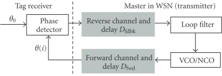
Figure 2is a block diagram of the common PLL scheme with a feedback structure. Considering a case of noiseless environment, the equivalent phase differential equation of the first-order sampling PLL is given by
θ(i)=θ(i−1)−2πKsin[θ(i−D)−θ0(i−D)], (1)
where sin(·) is the equivalent function of phase detection,
Dis the feedback delay,θ0 is the carrier phase of received
signal,θ(i) is the local acquired phase of receiver, andK is
the loop gain consistent with the phase adjustment stepsize factor of the first-order PLL. In master synchronization,
θ0 is regarded as the phase of local oscillator in the tag
receiver, and θ(i) as adjustable phase of transmitter. Since
the proposed feedback loop bridges over the transmitter and the receiver, the delays in forward and reverse wireless link should be both considered for its performance.
is equivalent to D = Df wd+ Df dbk. Consistent with the conventional principles of PLL, the phase of signal received
in tag node has a π/2 difference from its local phase at
the locked status. To achieve acquisition by this loop, the signal of local oscillator in receiver is requested with a same period as the received signal. The stability and performance
of synchronization is also impacted by loop gain K, and
feedback delayD.
Except for the sampling feedback loop based on sinu-soidal wave, the sawtooth and the pulse waveforms are generally employed as reference signals in feedback control systems. Because of the linear relation between the phase error and feedback control signal, the sawtooth reference signal is able to obtain a better stability. The phase differential equation of such a feedback loop is presented as
θ(i)=θ(i−1)−2πK[θ(i−D)−θ0(i−D)]. (2)
Defining g(t) as the periodic narrow pulse signal with
width τd, the sampling phase detection in tag receiver is
obtained by pulse coherent detection. Comparing the corre-lation output with the preset threshold, we can determined whether the receiver has achieved synchronization or not. In order to simplify the analysis, we adopt a rectangle pulse given by
where τd is the pulse width. Thus, the equivalent phase
differential equation of the feedback synchronization loop is
given by
When the correlation output exceeds the threshold, that
is to say, the phase difference between received pulse and
local phase in tag node is less than a pulse width, it can be determined that the acquisition is achieved. The phase
detector is a gated on-offcontrol function. The advantage
of pulse synchronization feedback loop is obvious that the tag receiver transmits no feedback when correlation output
is lower than threshold, that is Δθ < 2πτd/T, and the
master adjusts its phase by itself until it receives a feedback from tag receiver. That means tag receiver will not consume energy until the condition of synchronization acquisition is satisfied. Assisted by the multiple access code, the above scheme can not only achieve synchronization acquisition, but also activate a mass of tag receivers. It is intelligible that such a master synchronization has the advantages of low-power consumption and low complexity for the tag nodes in WSNs.
3. Stability Analysis
The master synchronization separates feedback control into two parts in transmitter and receiver. However, the stability
of this feedback loop is affected by adding the long delay caused by the forward and reverse wireless link. Since the phase detector is often a nonlinear feedback unit with respect to the phase, it is hard to obtain a closed-form solution of determining stability or convergence under most situations.
The stability analysis of sampling phase-locked loop
(SPLL) is given in [12,13]. At first, the transfer function of
SPLL should be obtained. According to (1), the Z-transform
of the transfer function near the locked status that sin(θ−
θ0)≈(θ−θ0) can be derived:
H1(z)= Θ(z)
Θi(z)=
2πKz−D
z−1+ 2πKz−D−1. (5)
The stability criteria for a feedback system is whether or not all the poles of the transfer function (or the roots of characteristic equation) lie in the unit circle. Once there is a pole outside the unit circle, the system is unstable. According to this principle, the stability boundary of the stepsize, that
is, the adjustment gainK, is derived as
K≤ 1
πsin π
2(2D−1). (6)
Obviously, the analysis of sawtooth-waveform-based system is similar with that of SPLL based. Because of linear
output of the sampling phase detectorUd(z)=2πK(θ0(z)−
θ(z)), its stability analysis result is closer to above theoretical
value.
Since the pulse-based master synchronization adopts decision feedback, its stability analysis involves the control theory. In the control theory, it is called as an act-and-wait type time-periodic control, where a more comprehensive
analysis is presented in [14–16]. The stability boundaries
for the given three master synchronization are analyzed and
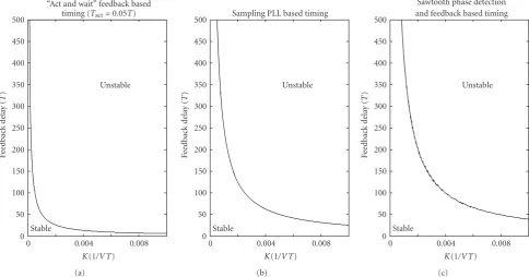
simulated. Suppose the signal period is T,Figure 3 shows
the stability margin with respect to the feedback loop gain
Kand the delayD. The stable region is on the left-hand side
of figure relative to the thick curve, and the right-hand side is unstable. The stability boundaries of sawtooth-waveform-and sine-waveform-based master synchronization is close
to the result of analysis in (6). When the feedback delay
increases, the gain K should be decreased to ensure the
stability of the feedback loop. If we consider the fading of wireless links in practice, the above result limits the range of the stepsize of phase adjustment in master node.
The stability of pulse-based master synchronization is
not only a function of loop gain K and feedback delay
D, but also the pulse width τd. To ensure the necessary
acquisition precision, the width of the narrow pulse is set as
τd =T/20 in analysis. According to the stability boundaries
chart shown inFigure 3, the available margin of pulse master
synchronization is much smaller than the other two types
given above. Furthermore, Figure 4 illustrates the stability
boundary with pulse widthτd = Tact and loop gain K at
D=100T. When the pulse width is greater than a threshold,
0.008
“Act and wait” feedback based timing (Tact=0.05T)
Sampling PLL based timing
Unstable
Sawtooth phase detection and feedback based timing
Unstable
Stable
(c) Figure3: Stability boundaries of master synchronization with feedback delays.
×10−3
Feedback delay=100T
Unstable Stable
Figure4: Stability chart of master synchronization atD=100T.
4. Applying Master Synchronization in WSNs
In order to reduce the power consumption of tag nodes, unnecessary feedback must be avoided in the master syn-chronization. In our proposed scheme, the acknowledge-ments are just transmitted at the time of satisfying the timing condition in tag receiver. That means a little energy may be cost in feedback. Therefore, it may be very beneficial to low-power working of the tag receiver. However, there are some problems to be solved in the following aspects. First,
the stability of the mast synchronization is influenced by the long-delay feedback. Second, the precise synchronization
required a small loop gainKwhich leads to large acquisition
time. Third, the detection probabilityPd <1 and the
false-alarm probability Pf a > 0 caused by the wireless channel
increase the average acquisition time and the transmitted energy in tag nodes obviously.
4.1. Stable Acquisition. The intuitive reason of instability in master synchronization is that the feedback control error departs from the right phase in master node due to the large delay. A simple method to ensure the stability of pulse master synchronization is by modulating the phase information into corresponding phase signal transmitted to tag node. After the tag node acquires this phase signal, that is, correlation exceeds the preset threshold, the carried phase information is fed back by the acknowledgement. Accepting the acknowledgement, the master node adjusts the VCO or NCO according to the phase information. Consequently, the phase of received signal would just agree with the phase of local oscillator in tag receiver.
Figure 5shows the signaling procedure mentioned above.
When there is burst data to the tag noden, the master node
transmits the synchronization signaling to the tag receiver
and adjusts its phase step by step. When the tag receivern
acquires the signal at the phasex, it demodulates the carried
phase information and feeds it back to the master node by acknowledgement, or directly relays it back. Acknowledged
by the tag noden, the master adjusts transmitter to the phase
x, and starts sending data.
Master in WSN
(output of the correlator excess
the threshold)
Figure5: Signaling of master synchronization in WSN.
signal with a pseudorandom multiaccess coded PCM signal. Adopting the multi-access code with a certain length not only resolves the problems of multi-access communication to tag nodes, but also reduces the synchronization false
alarm probability Pf a. Figure 6 shows the block diagram
of symbol-level master synchronization system. Here, the
integral window τd of the tag correlator, is the length of
multi-access code, not the pulse width.
4.2. Performance Analysis. The master synchronization is similar to the process of single dwell serial acquisition. In the traditional serial acquisition, the receiver needs to adjust the phase of local correlation template until it reaches consensus with that of the received signal. Different from serial acquisition, the adjustment of signal phase is transferred to the master transmitter in WSNs and the feedback has to be sent in wireless link. If the master synchronization requires
a precision in the interval of ±Tact, the searching stepsize
requires to be less thanTact. Noting that the synchronization
accuracy of ultra-wideband impulse is affected by many
factors, such as the searching stepsize, impulse waveform, multipath environment, modulation scheme, and decision
threshold [17,18], it is out of the range of this paper and
should be further studied for the proposed scheme.
The serial searching period, which is also the maximum searching time without considering the missed detections, is T2/Tact. The initial phase difference between the local
phase of the tag receiver and that of the received signal corresponds to the uniform distribution. The time delay
in feedback is denoted by D. In an ideal communication
channel, apparently, the average acquisition time of the pulse master synchronization is
Tacq=(1 +T/Tact)
2 ·T+D. (7)
In the case that there are error decisions of acquisition, the master synchronization has a problem of mistaking non-synchronous status as non-synchronous status, which is defined by false alarm probability. On the contrary, the synchronous status may be detected as non-synchronous status either. Its
probability is 1−Pd, wherePdis the detection probability. By
repeatedly sendingK-periodic synchronization signaling for
confirmation, the false alarm is eliminated with a penalty of
KTdelay. If the synchronization is not confirmed, the serial
search continues. Missing synchronization, the feedback system has to achieve acquisition in the next period of the serial search, which results in a long acquisition time.
In the communication of wireless sensor networks, the acknowledgement has to be delivered through wireless links. Not only should the false alarms and missed detections caused by the wireless fading and noise be considered, but also the feedback delay and the loss of acknowledgement in wireless channel may increase the acquisition time. Suppose
Pbk is the probability that the acknowledgement is correctly
received, the Markov chain acquisition model can be applied
to analyze the average acquisition time [19]. Using standard
signal flow graph reduction techniques, one arrives at the desired result, namely,
Tacq=2 + (2−PdPbk)(T/Tact−1)
If in addition T/Tact K, the variance of acquisition
time is obtained as
σ2
In the ideal case, the pulse master synchronization needs only the acquisition and confirmation acknowledgements. However, the false alarms may cause unnecessary feedbacks transmitted by the tag node. Apparently, the power con-sumption will increase with the increasing feedback times in the acquisition. Therefore, the average feedback time is an important parameter in the proposed master synchro-nization. Similar to the analysis above, it can be analyzed by
the probability methods. The average initial clock difference
is T/2Tact. When there is no missed detection and no lost
synchronization acknowledgement in the first search period,
the times of extra feedbacks areT/2Tact·Pf a. When there
is a missed detection or a lost acknowledgement in the first search period and no false in the second period, the extra
feedbacks are 3T/2Tact·Pf a. When the acquisition is arrived
in the third search period, the extra feedbacks are 5T/2Tact·
Pf a. The average feedback times can be deduced by analogy
Local clock Figure6: Diagram of master synchronization in WSN.
1
Single-step acquisition time Two-step acquisition time
Single-step feedback times Two-step feedback times
Figure7: Average acquisition time and feedback times.
Disregarding the lose of the synchronization acknowl-edgement, the average feedback times is inversely
propor-tional to the detection probability Pd and directly
propor-tional to the false alarm probabilityPf a. However, with the
common threshold decision in acquisition, the relationship
betweenPdandPf ais given by [19]
where B is the signal bandwidth,A2/N0B is the
signal-to-noise ratio (SNR), andQ−1(·) is the inverse function of Q
function. According to the equation, the false alarm prob-ability decreases when the detection probprob-ability decreases. Obviously, a minimum feedback times can be obtained with the small detection and false alarm probabilities. Unfortunately, the small detection probability would also greatly extend the acquisition time.
Under a certain Pbk and channel environment, it can
be seen that there is a minimum average acquisition time
according to (8) and (11). Suppose that Tact = 0.01T,
D = 5T,Pbk = 0.9, and an additive-white-Gaussian-noise
(AWGN) channel with SNR= −5 dB, the analysis results are
illustrated inFigure 7. AtPd ≈0.756, there exists a minimum
value of average acquisition time. It is worth noting that this
minimum point varies at different SNR andPbk.
5. Two-Step Acquisition
The pulse master synchronization has the advantages that single feedback and low complexity in tag receiver are required under ideal condition. At the same time, a main problem of master acquisition is that a highly precise synchronization with narrow pulse signal costs long time to be achieved. Take the ultra-wideband pulse for example,
the longest acquisition time is T2/Tact. In this view, we
propose a two-step acquisition scheme to limit acquisition time and feedback times in master synchronization, while guaranteeing the precision.
The two-step acquisition consists of two master
acquisi-tion processes. The main difference between the two steps is
the widths of synchronization pulses transmitted by master node. The two processes are as follows.
(1) In the first step of acquisition, the master node transmits periodic synchronization pulses with width
τw thatτw Tact to the tag node. The stepsize of
phase adjustment in master isτw. We also call it as
search stepsize. The correlation pulse generated in
the tag receiver keeps constant widthTact. The search
process is the same as the pulse master
synchroniza-tion described inSection 2. Thus, the search period
in the first step isT2/τ
w, and acquisition precision is
τw.
(2) The width of synchronization pulse sent by the
master node changes to Tact in the second step.
In a phase range acquired by first step, master node adjusts the phase of transmitting pulses by
stepsizeTact. With the same acquisition described in
Section 2, the search period in this stage isTτw/Tact.
Although the two-step acquisition scheme may increase the feedback times and power consumption, the cost is acceptable and the reduction of acquisition time is
remark-able. Suppose that the detection probability Pd and false
alarm probabilityPf aremain unchanged in the two steps of
0.5
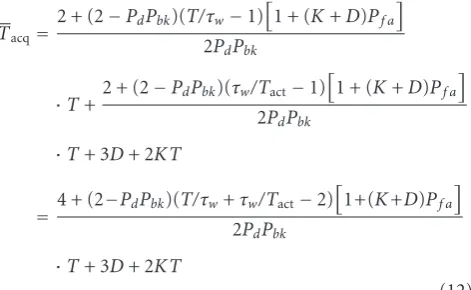
derived by the fact of the same processes in the two search
steps. The two-step acquisition time is given by (12).
In the proposed two-step acquisition, the optimum pulse width transmitted by master node in the first step
Tacq=2 + (2−PdPbk)(T/τw−1)
is chosen by minimizing acquisition time. From (12), we
obtain
where· denotes the integer ceiling operation andTacq(τw)
is the average acquisition time function of τw. From the
cost function (13), we can illustrate the optimum curve in
Figure 8. The optimum pulse width corresponding to the
minimum point ofTacq is derived thatτ0 = TTact. Since
τwis an integer multiple ofTactandTacqhas a less increment
atτw> τ0, we haveτw=
T/Tact ×Tact.
The average feedback times of the two-step master acquisition is an accumulation with feedback times of the two search stages. Therefore, it can be obtained that
N2=4 +Pf a
In exactly the same manner as described above, the optimum
τw according to (14) also satisfies the request by the
minimum feedback times.
By assigning τw as in (14), Figure 7also illustrates the
two-step acquisition curves of average acquisition time and average feedback times. The average acquisition time of the proposed two-step scheme is much less than that
of the single-step master acquisition with a same Pd. At
the same time, the difference of feedback times between
the single-step and two-step master acquisitions is small
at the region of short acquisition time. With a big Pd, the
feedback times of two-step search is even less than that of the single-step acquisition.
6. Simulations
In this section, the feasibility of the proposed master synchronization and the correctness of the analysis are demonstrated by simulations. We implement point-to-point simulations because the master synchronization is a physical-layer method in wireless sensor networks. The research of the proposed master synchronization mainly focuses on three contents including the stability, the acquisition time, and the feedback time (power consumption). The stability margins of master synchronization is obtained and analyzed. To break the stability constraint of the pulse master synchronization, the phase information is proposed to be carried by acknowledgement. The simulations of the acquisition time and the feedback time to verify the analysis are mentioned in the following part.
The simulation condition includes the period of pulses
denoted byT, the pulse widthTact=0.01T, and the feedback
delayD=5T. Suppose that the false alarm probability in tag
receivers and the feedback detection probability arePf a=0.1
and Pbk = 0.9, respectively. In the two-step scheme, the
optimum width of transmitted pulses in first step is τw =
0.1T according to (14). That determines the phase search
range of the second step.
Figure 9 is the comparison among the simulations of acquisition time and the analysis for single-step and two-step pulse master synchronization. Shown in the figure, the
acquisition time reduces when the detection probabilityPd
of the tag node increases at a certain Pf a. The proposed
two-step acquisition time is much less than that of the single-step scheme as expected. The consistency between the analytical curve and the results of simulations proves the correctness of the analysis. The feedback times with
respect to Pd is shown in Figure 10. Since that feedback
consumes the energy of tag node, fewer feedback times are able to maintain longer lifecycle in the proposed master synchronization. Shown as the curves, the two-step master acquisition requires much fewer feedback times than single-step acquisition. Besides, this conclusion is consistent with the theoretical results shown in the figure. Thus, the analysis
illustrated inFigure 7is credible. The limited feedbacks of
two-step scheme illuminates the feasibility of proposed pulse master synchronization in WSNs.
1
Single-step acquisition (simulation) Single-step acquisition (analytical) Two-step acquisition (simulation) Two-step acquisition (analytical)
Figure9: Average acquisition time with respect toPdin forward
channel.
Single-step acquisition (simulation) Single-step acquisition (analytical) Two-step acquisition (simulation) Two-step acquisition (analytical)
Figure10: Average feedback times with respect toPdin forward
channel.
feedback signal may be lost more probable by master node
than that in master-to-tag link. Therefore, the low Pbk is
nonnegligible according to the acquisition time analyzed in
(8) and (12). Supposing an ideal environment in
master-to-tag link, that is, Pd = 1 and Pf a = 0, and the loop gain
K = 0.26. We simulate and compare the acquisition times
0.9
Pack in reverse link 0
Saw phase-detection (simulation) Sample PLL (simulation)
Figure11: Average acquisition time with respect toPbkin reverse
link.
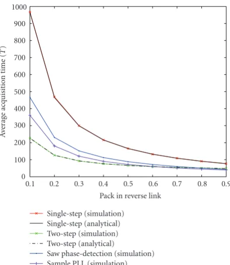
Tacq with differentPbk. The simulation and analysis results
from the single-step and two-step acquisitions are depicted in Figure 11. Sawtooth-waveform- and sine-waveform- (SPLL-) based master synchronization are also compared in the figure for their high convergence rate. From the results illustrated, the two-step pulse master synchronization still has a much faster acquisition than the single-step scheme. The theoretical curves are consistent with the simulations.
At a low Pbk, the acquisition time of the two-step pulse
scheme is even shorter than those of the sawtooth waveform
and sine waveform-based acquisitions. Only in highPbk, the
former has a little longer acquisition time, but much shorter than others as expected. Considering that the feedbacks are required in every signal period by the sawtooth and sine synchronization, their power consumptions by the tag node are much larger than that of the pulse master synchronization.
7. Conclusion
method in physical-layer synchronization of wireless sensor networks. And what is more, the synchronization tracking is another problem to be solved even in low burst-rate commu-nications. Fast estimation algorithms may be implemented to further reduce the complexity and power consumption with this distributed synchronization architecture.
Acknowledgments
This work was supported by National Natural Science Foundation (project 60962001, project 61071088) of China, and Guangxi Nature Science Foundation (project 0731026) in China.
References
[1] J. Yick, B. Mukherjee, and D. Ghosal, “Wireless sensor network survey,”Computer Networks, vol. 52, no. 12, pp. 2292–2330, 2008.
[2] M. Kohvakka, J. Suhonen, T. D. H¨am¨al¨ainen, and M. H¨annik¨ainen, “Energy-efficient reservation-based medium access control protocol for wireless sensor networks,”
EURASIP Journal on Wireless Communications and Network-ing, vol. 2010, Article ID 878412, 22 pages, 2010.
[3] L. Zhao, L. Guo, L. Cong, and H. Zhang, “An energy-efficient MAC protocol for WSNs: game-theoretic constraint optimiza-tion with multiple objectives,”Wireless Sensor Networks, vol. 1, pp. 358–364, 2009.
[4] N. A. Pantazis and D. D. Vergados, “A survey on power control issues in wireless sensor networks,” IEEE Communications Surveys & Tutorials, vol. 9, no. 4, pp. 86–107, 2007.
[5] O. B. Akan, M. T. Isik, and B. Baykal, “Wireless passive sensor networks,”IEEE Communications Magazine, vol. 47, no. 8, pp. 92–99, 2009.
[6] M. T. Isik and O. B. Akan, “PADRE: modulated backscattering-based PAssive data REtrieval in wireless sensor networks,” inProceedings of the IEEE Wireless Communications and Networking Conference (WCNC ’09), pp. 1–6, April 2009. [7] U. Mengali and A. D’Andrea,Synchronisation Techniques for
Digital Receivers, Kluwer Academic, Boston, Mass, USA, 1997. [8] J. Ammer and J. Rabaey, “Low power synchronization for wireless sensor network modems,” inProceedings of the IEEE Wireless Communications and Networking Conference (WCNC ’05), pp. 670–675, March 2005.
[9] N. C. McEwen et al., “A low-power, digital transceiver for wire-less sensor networks,” inProceedings of the 2nd IEE/EURASIP Conference on DSPenabled Radio, pp. 18–23, London, UK, September 2005.
[10] H. Xu and L. Yang, “Ultra-wideband technology: yesterday, today, and tomorrow,” inProceedings of the IEEE Radio and Wireless Symposium (RWS ’08), pp. 715–718, January 2008. [11] I. Demirkol, C. Ersoy, and E. Onur, “Wake-up receivers
for wireless sensor networks: benefits and challenges,”IEEE Wireless Communications, vol. 16, no. 4, Article ID 5281260, pp. 88–96, 2009.
[12] F. M. Gardner,Phase-Locked Techniques, John Wiley & Sons, New York, NY, USA, 3rd edition, 2005.
[13] J. Zheng, Principles and Applications of Phase-Locked Loop, People’s Posts and Telecommunications Press, China, 2nd edition, 1984.
[14] T. Insperger, P. Wahi, A. Colombo, G. St´ep´an, M. Di Bernardo, and S. J. Hogan, “Full characterization of act-and-wait control
for first-order unstable lag processes,”Journal of Vibration and Control, vol. 16, no. 7-8, pp. 1209–1233, 2010.
[15] T. Insperger, “Act-and-wait concept for continuous-time con-trol systems with feedback delay,”IEEE Transactions on Control Systems Technology, vol. 14, no. 5, pp. 974–977, 2006. [16] T. Insperger and G. St´ep´an, “Act-and-wait control concept for
discrete-time systems with feedback delay,”IET Control Theory and Applications, vol. 1, no. 3, pp. 553–557, 2007.
[17] N. He and C. Tepedelenlioglu, “Performance analysis of non-coherent UWB receivers at different synchronization levels,”
IEEE Transactions on Wireless Communications, vol. 5, no. 6, pp. 1266–1273, 2006.
[18] H. Xu and L. Yang, “Timing with dirty templates for low-resolution digital UWB receivers,”IEEE Transactions on Wireless Communications, vol. 7, no. 1, pp. 54–59, 2008. [19] M. K. Simon, J. K. Omura, R. A. Scholtz, and B. K. Levitt,