R E S E A R C H
Open Access
Performance of emerging multi-carrier
waveforms for 5G asynchronous
communications
Mathieu Van Eeckhaute
1*, André Bourdoux
2, Philippe De Doncker
1and François Horlin
1Abstract
This paper presents an extensive and fair comparison among the most promising waveform contenders for the 5G air interface. The considered waveform contenders, namely filter-bank multi-carrier (FBMC), universal-filtered multi-carrier (UFMC), generalized frequency-division multiplexing (GFDM) and resource-block filtered orthogonal frequency-division multiplexing (RB-F-OFDM) are compared to OFDM used in 4G in terms of spectral efficiency, numerical complexity, robustness towards multi-user interference (MUI) and resilience to power amplifier non-linearity. FBMC shows the best spectral containment and reveals to be almost insensitive to multi-user interference. It however suffers from its bad spectral efficiency for short bursts and from its poor multiple input multiple output (MIMO) compatibility. GFDM reveals to be the most promising contender, with the best spectral efficiency and the smallest complexity overhead compared to OFDM. It is also the most resilient to multi-user interference after FBMC and is MIMO compatible as soon as the interference can be managed. UFMC and RB-F-OFDM are finally the closest to OFDM and benefit therefore from a better compatibility with existing systems, even if their performance is generally lower than FBMC and GFDM.
Keywords: 5G air interface, Performance/complexity analysis, Multi-user interference, Non-linear communications
1 Introduction
The fourth generation of cellular networks (4G), Long Term Evolution (LTE), was introduced around 2010. It has essentially been optimized to provide high data band-width to strictly synchronized devices like tablets and smartphones [1]. In the near future, it is expected that the mobile internet will massively be used for machine-to-machine communications, introducing the concept of Internet-of-Things (IoT). In addition to a growing number of human-driven devices like smartphones with increas-ing data rates, the future fifth generation (5G) cellular networks will thus have to deal with Machine Type Com-munications (MTC). This new type of traffic will mainly be operated by low-end sensors. By nature, MTC will be sporadic, composed of small bursts and operated by a huge number of terminals. The 5G air interface will there-fore have to meet new requirements. Similarly to 4G, it will have to support users with high data rates but also
*Correspondence: [email protected]
1Université Libre de Bruxelles (ULB), Av. Roosevelt 50, 1050, Brussels, Belgium Full list of author information is available at the end of the article
a huge number of machine subscribers for which it must offer communications with low latency and be energy efficient [2].
The 4G air interface currently relies on a multi-carrier modulation scheme called orthogonal frequency-division multiplexing (OFDM). The multi-carrier nature of this waveform makes it very attractive in multi-path environ-ments since it allows one to consider each sub-carrier as affected by a frequency flat channel. The use of a cyclic prefix (CP) further makes the channel convolution cyclic, enabling an easy single-tap per sub-carrier equalization [3]. However, OFDM suffers from several shortcomings regarding the previously mentioned requirements for the future 5G cellular network [2]. Its sinc-shaped spectrum causes strong out of band radiations limiting its use in highly fragmented spectrum with lots of users. It is also very sensitive to time and frequency offsets, requir-ing strict synchronization to avoid interference between users. The CP together with the signalling messages required for synchronization introduce a lot of overhead, reducing the spectral efficiency.
New modulation formats must be considered for 5G communications. These new transmission schemes have to keep the OFDM advantages while addressing its draw-backs. They must therefore be more spectrally contained, be robust to time and frequency misalignments and exhibit a reduced overhead.
The most promising waveform candidates mentioned in the literature and that will be deeply investigated in this paper are listed below. They are mainly filtered versions of OFDM. The signal is filtered either on a sub-carrier basis or on a sub-band basis.
- The filter-bank multi-carrier (FBMC) and
generalized frequency-division multiplexing (GFDM) modulations filter the transmitted signal on a sub-carrier basis. In FBMC, long frequency-selective filters are used, drastically reducing the signal sidelobes compared to OFDM [4]. In GFDM, this filtering operation is done using a cyclic convolution, avoiding filter tails [5]. This makes GFDM
particularly interesting for short bursts.
- The universal filtered multi-carrier (UFMC) and resource-block filtered OFDM (RB-F-OFDM) modulations filter the signal on a sub-band basis using sharp filters. UFMC generates each sub-band using a full size inverse fast Fourier transform (IFFT) before filtering the time-domain signal using bandpass filters [6]. RB-F-OFDM rather generates each sub-band with a legacy small size OFDM transmitter and composes the transmitted signal by shifting in frequency the low-pass filtered OFDM signal of each sub-band [7].
The multi-antenna technology enables a significant increase of the capacity and reliability of the communi-cation links. The friendliness of the new waveforms to MIMO (multi-inputs multi-outputs) is investigated in the literature. Thanks to the use of the quadrature ampli-tude modulation (QAM) and the fact that they maintain orthogonality in the complex plain, UFMC and RB-F-OFDM offer full MIMO support, enabling the direct application of legacy OFDM MIMO techniques [6]. Due to their inherent self-interference, FBMC and GFDM are less straightforwardly MIMO compatible, especially con-cerning spatial multiplexing (SM) and space-time coding (STC). For GFDM, paper [8] shows that standard space-time block codes (STBC) applied directly to data symbols cannot be used. It rather develops a time-reversal-STC (TR-STC) technique shown to outperform STBC OFDM [9]. A dedicated GFDM near-maximum likelihood SM detection scheme able to deal with self-interference is developed in [10]. It is also shown to outperform SM OFDM as it exploits the self-interference as a source of extra frequency diversity. In FBMC, interference also prevent standard STBC Alamouti schemes to be reused for symbol-wise coding. A block-wise coding scheme was
therefore designed in [11]. A maximum likelihood SM detection scheme for FBMC able to compensate for the offset-QAM (OQAM) interference is proposed in [12]. Those dedicated STC and SM schemes for FBMC how-ever induce a complexity increase and suffer from a per-formance loss compared to equivalent OFDM schemes [11, 12]. MIMO schemes for FBMC and GFDM are still under development.
Several studies have already compared some of those waveforms individually to OFDM in a input single-output (SISO) case. An extensive comparison between OFDM and FBMC is provided in [13] in terms of spectral containment, spectral efficiency and complexity. Effects of time-frequency misalignments in FBMC are investi-gated in [14]. Benefits of UFMC over OFDM are partially presented in [15], but this analysis is limited to spectral efficiency aspects. An extensive comparison between the robustness to time-frequency misalignments of UFMC and OFDM is provided in [16]. The complexity aspects are not addressed in [15] and [16]. Paper [17] compares GFDM to OFDM in terms of complexity and spectral containment only, while [7] presents RB-F-OFDM and compares it to OFDM in terms of complexity, spectral containment, and spectral efficiency. The robustness to time-frequency misalignments is not addressed in [7].
However, no study exists in literature providing an comprehensive and fair comparison among all major 5G waveform contenders. Up to now, [18] and [19] partially address the problem by delivering a comparison between FBMC, UFMC and GFDM. RB-F-OFDM, being one of the most serious candidate because of its similarities with legacy OFDM systems, is however not considered in those two studies.
Moreover, [18] only focuses on the robustness to time-frequency misalignments of the different waveforms in a multi-user scenario. Other crucial aspects to meet new 5G requirements must be considered. Spectral containment is essential for use in a highly fragmented spectrum. Spectral efficiency and complexity are also important to provide low-latency transmissions and have low energy consump-tion. The robustness comparison to time-frequency mis-alignments provided in [18] is also somewhat limited since important measures improving robustness to time and frequency offsets are not considered. Paper [18] does not apply block windowing at the receiver in UFMC. The win-dowing reduces spectral leakage of adjacent asynchronous users [16]. Inserting guard symbols at the beginning and at the end of each block in GFDM improves the perfor-mance but [18] does not consider this technique in simula-tions. Additionally, time windowing can also be applied to each transmitted GFDM block. Although improving the performance, this windowing was not considered in [18].
power spectral density (PSD), spectral efficiency, peak-to-average-power ratio (PAPR) and complexity. Robustness to timing offset (TO) and carrier frequency offset (CFO) in a non-synchronous multi-user scenario is also stud-ied. However, the contribution of [19] is also limited since the spectral efficiency comparison was done considering an additive white Gaussian noise (AWGN) communica-tion channel only. In a multi-path channel environment, guard symbols have to be inserted in GFDM when win-dowing the blocks at the transmitter to allow proper channel equalization. Similar to OFDM, guard intervals have to be inserted in UFMC to combat inter-symbol interference (ISI) when subject to a multi-path chan-nel. This reduces the spectral efficiency of UFMC and GFDM compared to results in [19]. In terms of complex-ity, an efficient implementation of FBMC (using frequency spreading) is compared to suboptimal versions of UFMC and GFDM.
Paper [20] also recently proposed an overview of FBMC, GFDM and UFMC. It additionally includes F-OFDM in the comparison and recommends the latter waveform for 5G. However, this study does not contain any com-plexity analysis and does not take into account GFDM and FBMC when comparing the robustness to adjacent time-frequency misaligned users.
The goal of this paper is thus to provide a fair com-parison among the major waveform contenders assuming SISO transceivers as a first step. This study includes RB-F-OFDM and proposes a complexity analysis based on relevant reduced complexity implementations for all waveforms. Effects of guard intervals and windowing operations in UFMC and GFDM are also taken into account.
The rest of this paper is organized as follows. Section 2 will be devoted to a brief review of the different wave-forms, providing the necessary background to start the comparison among the contenders. Section 3 introduces the simulation parameters. The comparison of the dif-ferent candidates in terms of complexity, time-frequency
efficiency, robustness towards time-frequency misaligned users and resilience to non-linearity of the power ampli-fier is provided in Sections 4 to 7. Section 8 concludes the comparison by summarizing the performances of the investigated waveforms.
Throughout this paper, lowercase letters denote time-domain signals. Vectors are denoted by bold letters. Nota-tionsN,B,Landnbare used to designate the number of sub-carriers, the number of sub-bands, the length of a fil-ter and the number of multi-carrier symbols, respectively. Letterf denotes transmission filters whileg is used for reception filters. Subscriptkis used as sub-carrier index while subscripti denotes a sub-band index. Letters l,m and n are time indexes. Symbol CPL is used for cyclic prefix length. Waveform specific notations are defined in their corresponding sections, and important symbols used throughout the paper are recalled in Table 2.
2 Candidate air interfaces
The principle of the OFDM transceiver is already well known in the wireless community [21] and will there-fore not be presented here. This section introduces the new waveforms considered for 5G broadband commu-nications. To better highlight the operating principles, the presentation focuses on the conventional transceiver schemes. References to reduced complexity implementa-tions are also provided in the Appendix.
2.1 FBMC
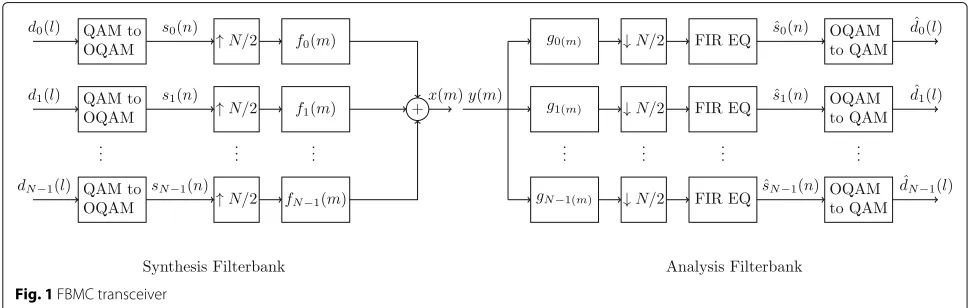
The operating principle of the FBMC transceiver is illus-trated in Fig. 1. FBMC addresses the spectral containment problem of OFDM by filtering the signal on a sub-carrier basis using a long prototype filterh(n)of length KN. N being the number of sub-carriers, this prototype filter isK times longer than a rectangular OFDM symbol.Kis called the overlapping factor since each FBMC symbol over-laps with K neighbouring symbols in the time domain. To avoid inter-symbol interference (ISI),h(n)respects the Nyquist criterion. The usual approach is to define a full
Nyquist filter by 2K −1 symmetric samples in the fre-quency domain, as proposed in [22]. The full Nyquist filter is split into two identical square root Nyquist filters, used as prototype filters at the transmitter and receiver sides. The corresponding time-domain prototype filterh(n) is generated by taking theKN-point IFFT of aK-point fre-quency domain square root Nyquist filter of roll-offβ =1. The transmitted FBMC signal is constructed as follows [23]. For thekth sub-carrier, the input QAM symbolsdk(l) up-sampled by a factorN/2 before convolution with the transmission filterfk(m). This filter is a shifted version of the prototype filter centred on thekth sub-carrier:
fk(m)=h(m)ej2πkmN , m=0, 1, ...,KN−1 (2) The transmitted FBMC baseband signal results from the summation of the filtered stream of each sub-carrier:
x(m)= Assuming a noiseless transmission and a perfect chan-nel, the received symbol at time indexn0and sub-channel indexk0is given by: the transmultiplexer response. The reception filtergk(m) is matched to the corresponding transmission filterfk(m). Looking at the transmultiplexer response given in Table 1, it is clear that the filtering operation destroys orthogonal-ity between sub-carriers.
The imaginary part of this transceiver impulse response crosses zero for even time indexes while the real part crosses zero for odd indexes. The OQAM processing described in (1) therefore restores orthogonality since it consists in alternating real and imaginary parts of the
QAM symbols in time for a specific sub-carrier while also alternating them between sub-carriers at a same instant. The up-sampling factor of 2 introduced in (1) allows one to maintain the throughput. To recover the estimated QAM symbols dˆk(l) at the receiver side, the OQAM demodulation process simply implements the reverse operation of (1).
It must be noted that the use of OQAM prevents legacy MIMO techniques to be reused in FBMC while long fil-ter tails make this scheme less attractive for short bursts. FBMC does also not include any guard period between transmitted symbols. Interference caused by the multi-path channel must therefore be compensated by a finite impulse response (FIR) equalizer before OQAM demodu-lation [25].
2.2 GFDM
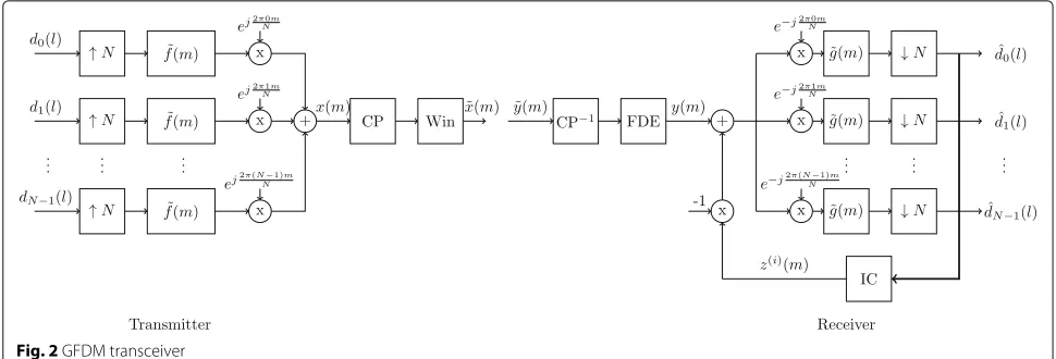
The principle of the GFDM transceiver is summarized in Fig. 2. Like FBMC, GFDM filters each sub-carrier indi-vidually. Besides the frequency dimension, it introduces an additional time dimension in data blocks. A GFDM symbol is composed ofMQAM symbols for each of the N sub-carriers. GFDM can thus be seen as a parallel SC system with frequency-domain equalization (FDE).
To avoid the long filter tails of FBMC, GFDM filters each sub-carrier using a circular filter defined as:
˜
wheref(m)is a root-raised-Cosine (RRC) filter of length MN, spanning theN-up-sampled GFDM symbol and of roll-offβ <1. The circular filtering, also called tail biting, allows one to keep the signal length unchanged before and after filtering. The discrete baseband signal for one GFDM block can thus be expressed as:
x(m)=
Before transmission, a CP is inserted in the signal, enabling a single-tap FDE at the receiver.
As in FBMC, the per-sub-carrier filtering introduces inter-carrier interference (ICI). Three common demodu-lation methods are mentioned in [5] that deals with this interference, namely the matched filter, zero-forcing, and
Table 1Example of transmultiplexer response forK=4 and evenk[24]
n−3 n−2 n−1 Number n+1 n+2 n+3
k−1 −0.0429 j −0.1250 0.2058 j 0.2393 −0.2058 j −0.1250 0.0429 j
k −0.0668 0.0002 0.5644 1.0000 0.5644 0.0002 −0.0668
Fig. 2GFDM transceiver
minimum mean square error receivers. In this paper, the matched filter receiver is used in combination with an Interference Cancellation (IC) algorithm. This approach presents the best trade-off between computational com-plexity and bit error rate (BER) performance [5]. Since an RRC filter is matched with itself, the receiver filters the signal of each sub-carrier with the same circular RRC filter as the transmitter, i.e.g˜(m)= ˜f(m).
Interference can also be considered as due to neigh-bouring sub-carriers only. ICI is thus suppressed using a double-sided serial interference cancellation (DSIC) scheme. This iterative IC scheme consists in estimating the interferencez(i)(m)for each sub-carrier and retrieving it to the received signaly(m). A complete iteration of the algorithm corresponds to the cleaning of all sub-carriers. A sub-iteration consists of cleaning a single sub-carrier and is denoted by indexi. The estimated interference of theith sub-iteration for thekth sub-carrier is given by:
z(i)(m)= k= {k−1,
k+1}
M−1
l=0
ˆ
d(ki)(l)g˜(m−lN)e−j2π
km
N (7)
where estimated symbols dˆ(ki) are obtained by mapping
received symbolsdk(i)to the constellation grid. The(k+1)th
sub-carrier is cleaned using the most recent estimated data symbols. It was shown by simulation that J = 4 full iterations for the IC algorithm allow a BER perfor-mance close to OFDM. No further gain is brought by additional iterations. This IC scheme however prevents legacy MIMO techniques to be straightforwardly applied. A drawback of the tail biting scheme is that it produces severe discontinuities between successive blocks, degrad-ing the spectral containment. We adopt the solution of [16] to reduce the out-of-band radiations. It consists in applying aMN-point RRC window to each GFDM block after CP insertion. To be robust to multi-path channels,
we also drop the first and last time slots of each GFDM block (i.e. we inserted GS= 2 guard symbols), avoiding windowing compensation at the receiver.
2.3 UFMC
Figure 3 illustrates the operating principle of the UFMC transceiver. UFMC filters the signal on a sub-band basis. The N carriers composing the bandwidth are sub-divided inBsub-bands of C adjacent sub-carriers each. Orthogonality between sub-carriers is maintained. This avoids the use of extra schemes like OQAM modulation and allows legacy MIMO techniques to be reused. We choose to filter each sub-bandiwith a Dolph-Chebyshev prototype filter fi(m) modulated around the centre fre-quency of the sub-band. This filter has a lengthLUFMCand a sidelobe attenuationα. The time-domain signalsi(n)of theith sub-band before filtering is obtained by parallel to serial conversion (P/S) of theN-point IFFT ofdi(l). Vector
di(l)is theC×1 array of QAM symbols loading sub-band iat timel[15]. For each block ofNQAM symbols, the dis-crete baseband UFMC signal is obtained by summing the filtered signals of each sub-band:
x(m)= B−1
i=0
L−1
n=0
si(n)fi(m−n) (8)
Fig. 3UFMC transceiver
enables a perfect mitigation of the channel time dispersion using a simple 1-tap FDE.
At the receiver side, a 2N-point FFT must be taken after serial to parallel (S/P) conversion to demodulate each UFMC symbol since they span N + LUFMC −1 +ZPL samples. Only theNeven bins of the 2N-FFT are consid-ered to retrieve the data symbols since all odd sub-carriers contain ICI [26]. Data symbols are finally recovered after 1-tap FDE.
2.4 RB-F-OFDM
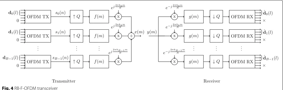
The operating principle of the RB-F-OFDM transceiver is depicted in Fig. 4. Similar to UFMC, RB-F-OFDM fil-ters the signal on a sub-band basis and orthogonality is maintained, allowing legacy MIMO techniques to be reused. TheNsub-carriers spanning the whole bandwidth are also organized in Bsub-bands, each composed ofC contiguous sub-carriers. UFMC generates each sub-band directly around its centre sub-carrier using a full sizeN -point IFFT. RB-F-OFDM rather uses a smaller OFDM transmitter with a R-point IFFT to generate the signal
si(n)of each sub-bandiin baseband. AsC<R, unloaded IFFT inputs are filled with zeroes. This signal is then up-sampled by a factorQ = N/R, and the baseband replica is filtered with a low-pass FIR equiripple filter f(m). As proposed in [7], this filter spansLRB-F-OFDMsamples, with a passband of C sub-carriers, a stop-band starting at the Rth sub-carrier, a stop-band slope of γ and a sidelobe attenuation α. The baseband replicas are finally modu-lated around the centre sub-carrier of each sub-band. The discrete baseband RB-F-OFDM signal results from the summation of those modulated sub-band signals:
x(m)= B−1
i=0
n
si(n)f(m−nQ)
ej2πkimN (9)
wherekiis the centre sub-carrier of theith sub-band. The receiver simply implements the reverse opera-tions of the transmitter, using the same prototype filter g(m) = f(m). Thanks to the CP insertion in the small OFDM transmitter, channel equalization can be simply performed using a 1-tap FDE. This CP insertion happens at a low rate and must cover transmission and reception
filtering operations. To offer the same robustness as a legacy OFDM transmitter with a CP length of CPL, the CP in RB-F-OFDM must span
CPL,RB-F-OFDM=
CPL+2LRB-F-OFDM
Q (10)
samples.
3 Simulation scenario
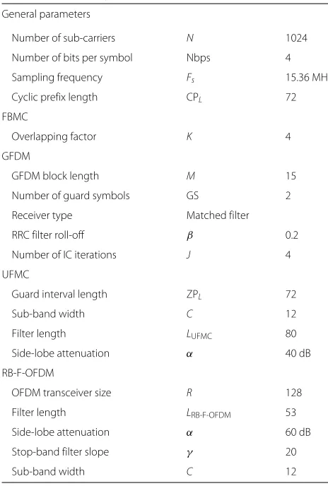
The next sections are dedicated to a detailed compari-son of the waveform candidates on key criteria for an application in 5G. All comparisons are conducted using parameters based on a typical 10-MHz bandwidth LTE scenario [28]. Those parameters are expected to remain representative for 5G broadband communications. Gen-eral simulation parameters are listed together with wave-form specific parameters in Table 2.
The performance study is organized as follows. Each comparison criterion is studied in a dedicated section, and a performance metric is introduced for each crite-rion. Those metrics are summarized in Fig. 12 providing a global performance overview.
Table 2Simulation parameters
General parameters
Number of sub-carriers N 1024
Number of bits per symbol Nbps 4
Sampling frequency Fs 15.36 MHz
Cyclic prefix length CPL 72
FBMC
Overlapping factor K 4
GFDM
GFDM block length M 15
Number of guard symbols GS 2
Receiver type Matched filter
RRC filter roll-off β 0.2
Number of IC iterations J 4
UFMC
Guard interval length ZPL 72
Sub-band width C 12
Filter length LUFMC 80
Side-lobe attenuation α 40 dB
RB-F-OFDM
OFDM transceiver size R 128
Filter length LRB-F-OFDM 53
Side-lobe attenuation α 60 dB
Stop-band filter slope γ 20
Sub-band width C 12
4 Time-frequency efficiency
4.1 Performance metric
The spectral efficiency can be defined as the product of the time efficiencyrtwith the frequency efficiencyrf:
rtf =rt×rf (11)
This spectral efficiency metric is proposed in [15] for UFMC only. It is a more relevant metric than the spec-tral efficiency defined in [19] that only takes into account the time overhead but discards the impact of out-of-band (OOB) emissions.
The frequency efficiency characterizes the spectral con-tainment of each waveform and is defined as:
rf = N
N+Nguard
(12)
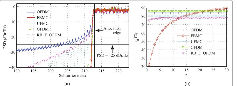
where N is the number of active sub-carriers equal to 600 in the LTE standard for a transmission bandwidth of 10 MHz.Nguard is the number of guard sub-carriers to insert after the allocation edge to reach an OOB PSD of −25 dB/Hz. Figure 5a illustrates the PSD of the dif-ferent waveform candidates near the allocation edge. In this figure,Nguardcorresponds to the difference between the carrier index of the allocation edge and the sub-carrier index corresponding to the last intersection of the PSD curve and the reference line at−25 dB/Hz.
The time efficiency quantifies the time overhead intro-duced in a transmission. It is defined similarly to [15] as:
rt= DL DL+TL
(13)
where DL is the number of samples in the transmitted signal dedicated to data and TL is the number of over-head samples (CP, filter tails,...). For all waveforms,DL = nb× N. Symbol nb denotes the number of transmitted multi-carrier symbols in a burst.
4.2 Performance comparison
It is clear from Fig. 5a that FBMC and GFDM are the most frequency efficient waveforms. The PSD of UFMC and RB-F-OFDM drops more slowly near the allocation edge since they are filtered on a sub-band basis. With its sinc-shaped spectrum, OFDM has the worst performance. The number of overhead samplesTLrequired to deter-mine the time efficiency (13) are provided below for each waveform.
• In OFDM, the overhead is exclusively due to the CP insertion:
TL,OFDM=nb×CPL. (14) • FBMC introduces a long filter tail in the signal that is
independent from the length of the burst:
Fig. 5 aPower spectral density near allocation edge. (N=1024,N=600.)bTime-frequency efficiency
This is particularly inefficient for small bursts.
• Compared to OFDM, UFMC introduces a filter tail
LUFMCin each block additionally to a zero prefix of same length as the OFDM CP:
TL,UFMC=nb×(ZPL +LUFMC−1).
(16)
• In GFDM, two guard symbols (GS) must be introduced, dropping the first and last time slots in each block. Additional to theN×GS overhead samples introduced in each block, the number of GFDM transmitted blocksnbGFDM=nb/Mmust be
multiplied byGSM+M to transmit the same number of symbols. This leads to:
TL,GFDM=nb,GFDM
GS+M
M ×(N×GS+CPL).
(17)
• In RB-F-OFDM,R−Czeroes are inserted to pad the small size IFFT in each block and a cyclic prefix is inserted at a low rate. The signal is up-sampled by a factorQ and filtered by a prototype filter of length
LRB-F-OFDM. This gives:
TL,RB-F-OFDM=nb×Q×(R
−C+CPL,RB-F-OFDM)
+LRB-F-OFDM−1 .
(18)
The resulting time-frequency efficiency is illustrated in Fig. 5b for all waveforms. The impact of the time effi-ciency dominates the impact of the frequency effieffi-ciency. Time-frequency efficiencies of Fig. 5b are closely related to those time efficiencies. With no filter tails, thanks to tail biting, with its reduced CP overhead due to an increased block size and with its good spectral containment, GFDM is the more time-frequency-efficient waveform for short
to medium bursts. It is outperformed by FBMC for long bursts. FBMC seems however not suited for short bursts where it is penalized by its long constant filter tails. Even if they are better spectrally contained, RB-F-OFDM and UFMC are outperformed by OFDM due to their extra fil-ter tails. RB-F-OFDM is less time-frequency efficient than UFMC due to the extended CP that must cover filters and due to the extra zeroes inserted in the small OFDM transmitter. Those results are summarized in the radar plot of Fig. 12 wherertf is computed for both short and long bursts, i.e. fornb = 1 and nb = 30, respectively, in Fig. 5b.
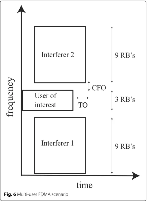
5 Robustness to time-frequency misaligned users 5G is expected to support a huge density of terminals. As outlined in [16], synchronicity will therefore be relaxed compared to LTE to limit the required transmission and complexity resources. This will however introduce multi-user interference (MUI) due to the residual TO and CFO between users. It is crucial that the air interface limits this loss of orthogonality.
5.1 Performance metric
Fig. 6Multi-user FDMA scenario
The MUI is assessed by measuring the mean square error (MSE) on the received symbols of the UoI. The met-ric summarizing the robustness of each waveform to the MUI is computed by measuring the number of guard sub-carriers to introduce between the user signals to make sure the MSE of the UoI reaches−30 dB.
5.2 Performance comparison
The robustness of each waveform to time-frequency mis-aligned users is illustrated in Fig. 7 depicting the MSE of the UoI as a function of the relative power of the interferers in the uplink asynchronous FDMA scenario. A noiseless transmission over a perfect channel is assumed. Making the power of the interferers vary simulates the potentially varying distances from the interferers in a dense scenario. As a first step, we consider that there is a single guard sub-carrier between the asynchronous users. It is the minimum value required by FBMC and GFDM to maintain the orthogonality between users even if they are perfectly synchronized. When no guard sub-carrier is inserted, the OQAM process and the iterative DSIC are indeed unable to mitigate interference on the neighbour-ing sub-carriers between adjacent users. It is clear from Fig. 7 that FBMC is least sensitive to the MUI, followed by GFDM while UFMC and RB-F-OFDM only slightly
Fig. 7MSE of the UoI in asynchronized uplink FDMA scenario as a function of the relative power of the interferers. Random TO and CFO in [−0.5, 0.5]
outperform OFDM in this case. Those performance dif-ferences can be explained using the reasoning developed in [18].
In a perfectly synchronized scenario, FBMC maintains the orthogonality between users, thanks to its excellent spectral containment. For all other waveform candidates including OFDM, the orthogonality between users comes from the perfect alignment of transmission and recep-tion windows. The MUI introduced by time and frequency misalignments between users is closely linked to the spec-tral leakage due to transmission and reception filters.
As OFDM only applies a rectangular window at the transmitter and the receiver, it is logically the most sensi-tive to MUI.
The excellent performance of FBMC is explained by the long frequency-selective filters applied on a sub-carrier basis at the transmitter and the receiver.
GFDM filters each sub-carrier individually at the trans-mitter and the receiver but uses a circular convolution. Discontinuities between blocks due to tail biting are attenuated by windowing the transmitted blocks before transmission. This reduces the spectral leakage at the transmitter. Paper [16] showed that inserting two guard symbols as done here further enhances the spectral con-tainment. Figure 7 proves that windowing and inserting two GS indeed makes GFDM less sensitive to MUI, per-forming close to FBMC.
outperforms OFDM when one guard sub-carrier between users is considered.
As UFMC only filters the signal on a sub-band basis at the transmitter, spectral leakage cannot be mitigated at the receiver without extra processing. In practice, the MUI performance of UFMC was improved by applying a raised cosine window on the received signal before the 2N-point FFT at the receiver. This window spansN + ZPL+LUFMC −1 samples. This windowing introduces a convolution effect in the frequency domain explaining the saturation of the MSE when the power of the inter-ferers becomes negligible compared to the UoI. Figure 7 however shows that it globally improves the MUI robust-ness since UFMC slightly outperforms RB-F-OFDM for PUoI/Pinterf < 20 dB. Saturation effects for FBMC and GFDM are, respectively, due to the residual interference of the transmultiplexer and to the limited efficiency of the DSIC.
The MUI robustness of each waveform is summarized in Fig. 12 by reporting the guard band to insert between users to reach an MSE of−30 dB for the user of interest. Those necessary guard sub-carriersNguardare reported in Table 3, considering the same power for the interferers and the user of interest.
When spacing adjacent users in frequency, the MUI robustness of UFMC and RB-F-OFDM is considerably improved compared to Fig. 7. This is due to the per sub-band filtering of those waveforms reducing drastically the OOB emissions in the far band while this contain-ment remains limited next to the allocation edge. FBMC and GFDM that are filtered on a sub-carrier basis have already an excellent spectral containment near the allo-cation edge, explaining their good MUI robustness even for a limited frequency spacing between users. OFDM is logically far behind new waveforms.
6 Numerical complexity
Since new waveforms apply extra filtering operations compared to OFDM, a complexity analysis is required to ensure that the introduced complexity overhead does not compromise the energy efficiency of the air interface.
6.1 Performance metric
The numerical complexity of each contender is evaluated as the number of required real multiplications for trans-mission and reception of a given number of multi-carrier symbols. The associated complexity metric depicted in Fig. 12 is defined for each waveform as
Table 3Guard sub-carriers in asynchronous scenario
OFDM FBMC UFMC GFDM RB-F-OFDM
Nguard 80 1 7 1 12
rC,w= Cw COFDM
(19)
whereCwandCOFDM are the number of real multiplica-tions required to transmit a single multi-carrier symbol for thewth waveform and OFDM, respectively.
6.2 Performance comparison
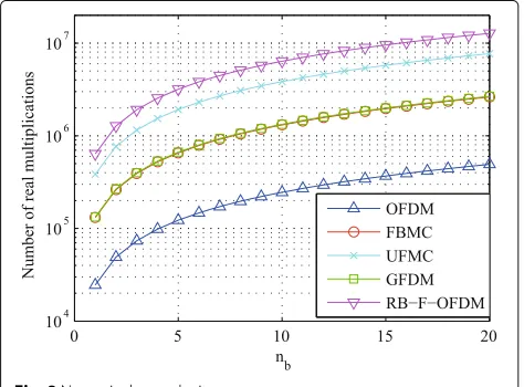
The numerical complexity of all candidates as a function of the length of the transmitted data sequence is illus-trated in Fig. 8. Those complexity curves are obtained considering low complexity equivalent implementations of the transceivers presented in Section 2. Detailed com-plexity analysis is provided in the Appendix.
Table 4 summarizes the complexity overhead of each waveform compared to OFDM. Those overheads are globally limited, thanks to the frequency domain and polyphase implementations of all filtering operations. The most computationally efficient new waveforms are FBMC and GFDM, being five times more complex than OFDM. RB-F-OFDM and UFMC present a higher complexity since each sub-band is generated using FFT operations spanning 10 times more points than the number of data symbols to modulate.
7 Resilience to power-amplifier non-linearity To minimize the power consumption and therefore ensure a good energy effiency, power amplifiers are driven near their saturation point at the transmitter, introducing sig-nificant non-linearity. The robustness of a waveform to non-linearity is essential since it introduces spectral regrowth (i.e. a broadening of the spectrum) and in-band distortion degrading the transmission MSE [29].
7.1 Performance metrics
The PAPR is often taken as reference to characterize the sensitivity of a signal to non-linear distortions introduced
Table 4Complexity overhead compared to OFDM
FBMC UFMC GFDM RB-F-OFDM
rC 5.33 15.64 5.42 25.94
by a non-linear power amplifier (NL PA). This sensitiv-ity is however not fully characterized by the PAPR. In this work, the robustness to a NL PA is therefore addition-ally characterized using two distinct metrics to quantify the spectral regrowth and in-band distortion. This study is more accurate than the one proposed in [19] that exclu-sively relies on a PAPR analysis. The formalism of [30] is adopted to quantify spectral regrowth and in-band dis-tortion. In this section, the drive level of the NL PA is characterized by the output back-off (OBO). This OBO is defined as:
OBO (dB)=10 log10 Psig Psat
(20)
wherePsatis the saturating power of the PA andPsigis the mean power of the transmitted signal.
To quantify the robustness to spectral regrowth of each candidate, we measure the maximum OBO (OBOSR max) of the PA such that the spectrum of the amplified signal is still contained in a given emission mask. The consid-ered emission mask is illustrated in Fig. 10. This mask is inspired from [30].
The in-band distortion is quantified by the maxi-mum allowable OBO such that the receiver MSE reaches
−25 dB.
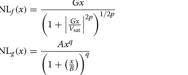
As advised in [31], the NL PA was simulated using a modified Rapp model characterized by the AM-AM dis-tortion function NLf(x)and AM-PM distortion function NLg(x)given below:
NLf(x)= Gx 1+VGx
sat 2p
1/2p (21)
NLg(x)=
Axq
1+Bx
q (22)
wherexdenotes the amplitude of the input signal. Param-eters of this PA model are summarized in Table 5.
7.2 Performance comparison
A first insight on the sensitivity of each candidate to PA non-linearity is provided by the PAPR complementary cumulative distribution function (CCDF) curves depicted
Table 5PA model parameters
G Vsat p A B q
1 1 2 −0.45 0.88 3.43
in Fig. 9. Those curves were obtained conducting a simu-lation over 100,000 multi-carrier symbols. All candidates perform very closely to OFDM since they are all multi-carrier waveforms with the same number of sub-channels. UFMC presents a slightly higher PAPR (0.5 dB) than the other waveforms. It is worth noting that GFDM was orig-inally presented in [32] as having a lower PAPR than OFDM, thanks to its parallel single-carrier nature. This is however only true if the number of GFDM sub-carriers is lower than in OFDM. Simulations show that reduc-ing the number of sub-carriers in GFDM also reduces its spectral containment. This would destroy its immunity to MUI and reduce its spectral efficiency, making it globally less attractive. In this paper, we therefore only consider the case of a high number of sub-carriers and show that GFDM is an attractive candidate.
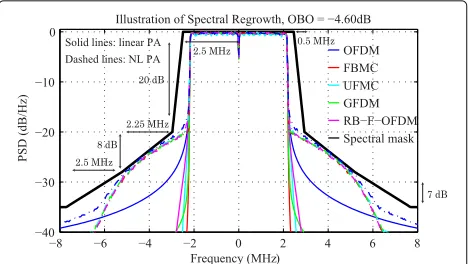
Spectral regrowth is depicted in Fig. 10 for all wave-forms, assuming an OBO equal to −4.60 dB. The max-imum OBO’s to reach the defined emission mask are given for each waveform in Table 6. As explained above, those OBO’s quantify the spectral regrowth sensitivity. The higher the maximum OBO, the closer the PA can be driven near its saturation point, i.e. the better the energy efficiency.
GFDM is the most robust to spectral regrowth, followed by RB-F-OFDM. As will be explained when treating of in-band distortion, FBMC suffers from the loss of OQAM orthogonality due to phase distortion. This explains why FBMC is outperformed by GFDM and RB-F-OFDM that are less spectrally contained. UFMC suffers from its slightly higher PAPR. OFDM still presents the worst per-formance. Those results are summarized in Fig. 12 where OBOSR maxvalues of Table 6 are reported.
The in-band distortion sensitivity of each waveform is quantified in Table 7 depicting the maximum OBO (OBOID max) such that the receiver MSE reaches−25 dB. The receiver MSE of each waveform as a function of
Fig. 10Spectral regrowth, 64QAM, modified Rapp PA,p=2
the OBO is illustrated in Fig. 11 where OBO values of Table 7 correspond to the intersection between the MSE curve of each waveform and the line corresponding to an MSE of−25 dB. Those results were obtained using a single user and perfectly synchronized scenario. For all modulations, the phase distortion introduced by the mod-ified Rapp PA was partially compensated at the receiver. Any phase rotation is generally included in the channel estimate and is compensated during symbol equalization. However, the 64QAM constellation exhibits symbols with different amplitudes. Symbols with the highest amplitude will undergo a higher phase rotation than symbols closer to the constellation centre. The phase compensation of the equalizer is thus not able to perfectly correct the PA phase distortion.
Looking at the OBO values of Table 7, we notice that OFDM performs the best, followed by RB-F-OFDM and GFDM. UFMC suffers from its higher PAPR. The bad performance of FBMC is due to the use of the OQAM modulation. A non-linear PA distorts the signal in ampli-tude and in phase. This generally causes an ampliampli-tude spreading together with a rotation of the QAM constel-lation. Due to OQAM, the OQAM demodulated FBMC received constellation does not suffer from this rotation but the phase distortion of (22) creates an additional amplitude spreading on demodulated QAM symbols. This phenomenon can be explained following the reasoning provided in [33]. Simulations showed that the additional amplitude spread on QAM symbols caused by the phase distortion introduces a bigger MSE degradation than the
Table 6Maximum OBO needed to respect the emission mask, 64QAM
OFDM FBMC UFMC GFDM RB-F-OFDM
OBOSR max −4.60 dB −4.34 dB −4.48 dB −4.28 dB −4.30 dB
Table 7maximum OBO for MSE<−25 dB, 64QAM
OFDM FBMC GFDM UFMC RB-F-OFDM
OBOID max −7.51 dB −8.70 dB −7.82 dB −7.92 dB −7.53 dB
phase rotation on the constellation of the other waveforms that do not use OQAM, and this at the same drive level of the PA. This increased sensitivity of FBMC could not be explained by simply referring to the PAPR curve of Fig. 9.
The in-band distortion sensitivity of each contender is summarized in Fig. 12 where OBOID max values from Table 7 are plotted.
8 Discussion
A global performance overview is provided in Fig. 12 sum-marizing the main results obtained from the comparison of the previous sections.
Candidates were first compared in terms of spectral effi-ciency by computing their time-frequency effieffi-ciency. The time-frequency efficiency of each waveform is described in Fig. 12 byrtfshort andrtflong for short and long bursts, respectively. FBMC suffers from its long filter tails when transmitting short bursts. GFDM is the most spectrally efficient candidate for short bursts thanks to its good spectral containment near the allocation edge. Its reduced CP overhead provided by its particular block structure also improves its performance. Due to the insertion of guard symbols, it is outperformed by FBMC for long bursts.
We also showed that the robustness to non-synchronized users was closely linked to the spectral containment of the waveform near its allocation edge. FBMC is almost insensitive to time and frequency offsets, followed by GFDM, while OFDM was found to be far
Fig. 12Performance overview
more sensitive than all other candidates. In Fig. 12, this is reflected by the required guard band between non-synchronized adjacent users inserted to limit the loss of orthogonality as described in Section 5.
New candidates suffer from a numerical complexity overhead compared to OFDM due to their additional filtering operations. The complexity overhead of each can-didate compared to OFDM is illustrated by the metric rC in Fig. 12. Considering optimized implementations, we derived that FBMC and GFDM require five times more real multiplications than OFDM to transmit the same amount of data symbols. Efficient implementations of UFMC and RB-F-OFDM are respectively 15 and 25 times more complex than OFDM.
We finally described the sensitivity of each contender to non-linearity of the PA in terms of spectral regrowth and in-band distortion. Due to their multi-carrier nature, all waveforms require a high output back-off to limit the band distortion. FBMC is the most sensitive to in-band distortions since it suffers from the use of OQAM. All candidates perform similarly with respect to spectral regrowth. New waveforms still outperform OFDM thanks to their better spectral containment.
The major problem of OFDM is its poor spectrum uti-lization in a dense non-synchronous scenario, which is a typical scenario expected for 5G.
Being the more robust to non-synchronous adja-cent users and presenting the smallest complexity over-head compared to OFDM, GFDM and FBMC seem the more promising contenders. FBMC however suffers from a poor time-frequency efficiency for short bursts. The inherent self-interference in FBMC and GFDM
also require an adaptation of legacy OFDM MIMO schemes.
9 Conclusions
This paper provided an extensive comparison of the main new waveform contenders for an application in the 5G air interface.
We compared FBMC, GFDM, UFMC and RB-F-OFDM in terms of time-frequency containment (spectral effi-ciency and robustness to time-frequency misaligned users) and energy efficiency (numerical complexity and resilience to power amplifier non-linearity). Their per-formances were compared to OFDM used in LTE. Pre-senting the best energy efficiency after OFDM and the best time-frequency containment among all contenders, GFDM seems the most suited waveform for an application in 5G, followed by FBMC.
Even if they perform less well, RB-F-OFDM and UFMC remain attractive because of their easier backward com-patibility than GFDM with legacy OFDM systems, espe-cially for MIMO techniques.
Appendix
Detailed complexity analysis
This Appendix provides a detailed derivation of complex-ity expressions leading to complexcomplex-ity curves in Fig. 8. The numerical complexity of each contender is computed as the numbernbof real multiplications for transmission and reception of a fixed number of multi-carrier symbols. An FFT or IFFT operation is considered as requiringNlog2N real multiplications and a multiplication between two complex numbers as requiring four real multiplications. Only channel equalization is taken into account, but not the equalizer computation.
OFDM
An OFDM transceiver mainly consists of aN-point FFT at the transmitter followed by aN-point IFFT at the receiver and a 1-tap FDE requiring N multiplications between complex equalizer coefficients and complex FFT outputs [21]. The numerical complexity of an OFDM transceiver is therefore given by
COFDM=nb
2Nlog2N+4N
(23)
FBMC
CFBMC, TX=2×nb
For GFDM, we consider a frequency domain equivalent implementation. We refer to papers [34] and [17] for the derivation of the efficient transmitter and receiver schemes, respectively. At the transmitter, each sub-carrier is modulated using an M-point FFT. After a frequency domain up-sampling by a factor 2, the signal is filtered by a 2M-point frequency domain filter and anNM-point IFFT is taken on all sub-carriers to generate the transmitted signal. The principle of the receiver is analogous, except that it includes an additional frequency domain equiva-lent of the DSIC algorithm described in Section 2. This algorithm is repeatedJtimes and requires to takeNtimes a M-point FFT and a M-point IFFT with an additional frequency domain filtering with anM-point real interfer-ence filter. To transmit the same number of symbols, the number of GFDM blocks must be divided by the number of time slots :nb,GFDM = nb/M. The 1-tap FDE before demodulation must also be taken into account. It consists of anNM-point FFT followed by anNM-point IFFT with NM complex multiplications in between to perform the equalization.
The complexity of UFMC is assessed considering the efficient scheme presented in [35]. This implementation relies on the 2N-point FFT based receiver presented in Section 2. The transmitter is however replaced by an equivalent scheme implementing the filtering operations in the frequency domain and using smaller IFFT’s to gen-erate the signal. This transmitter modulates each of the B sub-bands as follows. The C frequency domain sym-bols are first brought to time domain using anNifft-point IFFT, withNifft = 128. This time-domain signal is then brought back to the frequency domain by a 2Nifft-point FFT and filtered by a 2Nifft-point frequency domain com-plex filter. The time-domain transmitted signal is finally generated taking a 2N-point IFFT of the combinedB fre-quency domain signals of each sub-band. This leads to
CUFMC, TX=nb
We used the low-complexity polyphase equivalent imple-mentation presented in [7] to assess the computational complexity of RB-F-OFDM. The transmitter consists first of B small OFDM transmitters, as described in Section 2. Those transmitters are composed of an R -point IFFT among which onlyCsub-carriers are loaded. Those OFDM signals then enter a G-point IFFT, with G = N/C. The complex signal finally enters an synthe-sis polyphase network composed ofGbranches of real-valued LRB-F-OFDM
Q -point polyphase filters. The principle of the receiver is similar, except that a 1-tap FDE is done for each sub-band at the output of each OFDM receiver. This adds 4C extra real multiplications per multi-carrier symbol.
This work was supported by the European Regional Development Fund (ERDF) and the Brussels-Capital Region within the framework of the Operational Programme 2014-2020 through the ERDF-2020 project ICITY-RDI.BRU. We also thank FNRS/FRIA for financial support.
Competing interests
The authors declare that they have no competing interests.
Author details
1Université Libre de Bruxelles (ULB), Av. Roosevelt 50, 1050, Brussels, Belgium. 2Inter-university Micro-Electronics Centre (IMEC), Kapeldreef 75, 3001, Leuven, Belgium.
Received: 5 October 2016 Accepted: 26 January 2017
References
2. JG Andrews, S Buzzi, W Choi, SV Hanly, A Lozano, ACK Soong, JC Zhang, What will 5G be? IEEE J. Sel. Areas Commun.32(6), 1065–1082 (2014). doi:10.1109/JSAC.2014.2328098
3. Z Wang, GB Giannakis, Wireless Multicarrier Communications. IEEE Signal Process Mag.17(3), 29–48 (2000). doi:10.1109/79.841722
4. MG Bellanger, FBMC physical layer: a primer. Technical report, PHYDYAS (2010). http://www.ict-phydyas.org/teamspace/internal-folder/FBMC-Primer_06-2010.pdf. Accessed 4 Oct 2016
5. N Michailow, R Datta, S Krone, M Lentmaier, G Fettweis, inGerman Microwave Conference (GeMiC). Generalized Frequency Division Multiplexing: A Flexible Multi-Carrier Modulation Scheme for 5th Generation Cellular Networks, (2012). https://mns.ifn.et.tu-dresden.de/ Lists/nPublications/Attachments/809/main.pdf
6. T Wild, F Schaich, Y Chen, in19th International Conference on Digital Signal Processing. 5G Air Interface Design Based on Universal Filtered
(UF-)OFDM, (2014), pp. 699–704. doi:10.1109/ICDSP.2014.6900754 7. J Li, E Bala, R Yang, Resource Block Filtered-OFDM for Future Spectrally
Agile and Power Efficient Systems. Phys. Commun.11, 36–55 (2014). doi:10.1016/j.phycom.2013.10.003
8. M Matthe, LL Mendes, I Gaspar, N Michailow, D Zhang, G Fettweis, Multi-user time-reversal stc-gfdma for future wireless networks. EURASIP J. Wirel. Commun. Netw.2015(1), 132 (2015). doi:10.1186/s13638-015-0366-6 9. SA Cheema, K Naskovska, M Attar, B Zafar, M Haardt, inWSA 2016; 20th International ITG Workshop on Smart Antennas. Performance comparison of space time block codes for different 5G air interface proposals, (Munich, 2016), pp. 1–7
10. M Matthe, I Gaspar, D Zhang, G Fettweis, in2015 IEEE 82nd Vehicular Technology Conference (VTC2015-Fall). Near-ml detection for mimo-gfdm, (2015), pp. 1–2. doi:10.1109/VTCFall.2015.7391033
11. M Renfors, T Ihalainen, TH Stitz, in2010 European Wireless Conference (EW). A block-Alamouti scheme for filter bank based multicarrier transmission, (2010), pp. 1031–1037. doi:10.1109/EW.2010.5483517
12. R Zakaria, DL Ruyet, M Bellanger, in2010 European Wireless Conference (EW). Maximum likelihood detection in spatial multiplexing with fbmc, (2010), pp. 1038–1041. doi:10.1109/EW.2010.5483520
13. B Farhang-Boroujeny, OFDM Versus Filter Bank Multicarrier. IEEE Signal Process Mag.28(3), 92–112 (2011). doi:10.1109/MSP.2011.940267 14. T Fusco, A Petrella, M Tanda, in3rd International Symposium on
Communications on Communications, Control and Signal Processing. Sensitivity of Multi-User Filter-Bank Multicarrier Systems to Synchronization Errors, (2008), pp. 393–398.
doi:10.1109/ISCCSP.2008.4537257
15. F Schaich, T Wild, Y Chen, in79th IEEE Vehicular Technology Conference. Waveform Contenders for 5G—Suitability for Short Packet and Low Latency Transmissions, (2014), pp. 1–5.
doi:10.1109/VTCSpring.2014.7023145
16. M Kasparick, Y Chen, J-B Doré, M Dryjanski, IS Gaspar, 5G Waveform Candidate Selection D 3.2. Technical report, 5GNow (2014). http://www. 5gnow.eu/wp-content/uploads/2015/04/5GNOW_D3.2_final.pdf. Accessed 30 Dec 2016
17. I Gaspar, N Michailow, A Navarro, E Ohlmer, S Krone, G Fettweis, in77th IEEE Vehicular Technology Conference. Low Complexity GFDM Receiver Based on Sparse Frequency Domain Processing, (2013), pp. 1–6. doi:10.1109/VTCSpring.2013.6692619
18. A Aminjavaheri, A Farhang, A RezazadehReyhani, B Farhang-Boroujeny, in
IEEE Signal Processing and Signal Processing Education Workshop. Impact of timing and frequency offsets on multicarrier waveform candidates for 5G, (2015), pp. 178–183. doi:10.1109/DSP-SPE.2015.7369549
19. R Gerzaguet, D Kténas, N Cassiau, J-B Doré, Comparative study of 5G waveform candidates for below 6 GHz air interface. Technical report,LETI, CEA Tech (2016). https://docbox.etsi.org/Workshop/2016/
201601_FUTURERADIOTECHNOL_WORKSHOP/
S05_NEW_RADIO_ACCESS_TECHNO_SERV_ENVIR_PART_2/
5G_WAVEFORM_COMPARATIVE_STUDY_BELOW_6GHZ_KTENAS_CEA_LETI. pdf
20. X Zhang, L Chen, J Qiu, J Abdoli, On the waveform for 5G. IEEE Commun. Mag.54(11), 74–80 (2016). doi:10.1109/MCOM.2016.1600337CM 21. YS Cho, J Kim, WY Yang, CG Kang,MIMO-OFDM Wireless Communications
with MATLAB. (Wiley, 2010). doi:10.1002/9780470825631.refs http://dx.
doi.org/10.1002/9780470825631.refs
22. MG Bellanger, inIEEE International Conference on Acoustics, Speech, and Signal Processing. Specification and design of a prototype filter for filter bank based multicarrier transmission, vol. 4, (2001), pp. 2417–2420. doi:10.1109/ICASSP.2001.940488
23. M Payaró, A Pascual-Iserte, M Nájar, inEuropean Wireless Conference. Performance comparison between FBMC and OFDM in MIMO systems under channel uncertainty, (2010), pp. 1023–1030.
doi:10.1109/EW.2010.5483521
24. S Van Caekenberghe, S Pollin, A Bourdoux, L Van der Perre, J Louveaux, in
32nd WIC Symposium on Information Theory in the Benelux.
Preamble-Based Channel Estimation for Filterbank Multicarrier Wireless Systems, (Brussels, 2010)
25. J Louveaux, L Baltar, D Waldhauser, M Renfors, M Tanda, C Bader, E Kofidis, PHYDYAS D 3.1. Technical report, PHYDYAS (2008). www.ictphydyas.org/ delivrables/PHYDYAS-D3.1.pdf/at_download/file. Accessed 20 Sept 2016 26. X Wang, T Wild, F Schaich, A Fonseca dos Santos, in20th European
Wireless Conference. Universal Filtered Multi-Carrier with Leakage-Based Filter Optimization, (Barcelona, 2014), pp. 1–5
27. X Wang, Channel Estimation and Equalization for 5G Wireless Communication Systems Master’s thesis. Institut für Nachrichten übertragung, Universität Stuttgart (2014)
28. SS Prasad, CK Shukla, RF Chisab, inThird International Conference on Computing Communication Networking Technologies. Performance analysis of OFDMA in LTE, (2012), pp. 1–7. doi:10.1109/ICCCNT.2012.6395933 29. F Horlin, A Bourdoux,Digital Compensation for Analog Front-Ends: a New
Approach to Wireless Transceiver Design. (Wiley, Chichester, 2008) 30. A Maltsev, A Lomayev, A Khoryaev, A Sevastyanov, R Maslennikov, in7th
IEEE Consumer Communications and Networking Conference. Comparison of Power Amplifier Non-Linearity Impact on 60 GHz Single Carrier and OFDM Systems, (2010), pp. 1–5. doi:10.1109/CCNC.2010.5421601 31. M Webster, K Halford, Suggested PA Model for 802.11 HRb. Technical
report, Intersil Corporation (2000). http://www.ieee802.org/11/ Documents/DocumentArchives/2000_docs/02948Sb-Suggested%20PA %20Model%20for%20802.11%20HRb.ppt. Accessed 20 Sept 2016 32. G Fettweis, M Krondorf, S Bittner, in69th IEEE Vehicular Technology
Conference. GFDM - Generalized Frequency Division Multiplexing, (2009), pp. 1–4. doi:10.1109/VETECS.2009.5073571
33. H Bouhadda, H Shaiek, D Roviras, R Zayani, Y Medjahdi, R Bouallegue, Theoretical analysis of BER performance of nonlinearly amplified FBMC/OQAM and OFDM signals. EURASIP J. Adv. Signal Process.2014(1), 1–16 (2014). doi:10.1186/1687-6180-2014-60
34. N Michailow, I Gaspar, S Krone, M Lentmaier, G Fettweis, inInternational Symposium on Wireless Communication Systems. Generalized frequency division multiplexing: analysis of an alternative multi-carrier technique for next generation cellular systems, (2012), pp. 171–175.
doi:10.1109/ISWCS.2012.6328352
35. T Wild, F Schaich, inIEEE 81st Vehicular Technology Conference. A Reduced Complexity Transmitter for UF-OFDM, (2015), pp. 1–6.
doi:10.1109/VTCSpring.2015.7145643
Submit your manuscript to a
journal and benefi t from:
7Convenient online submission 7Rigorous peer review
7Immediate publication on acceptance 7Open access: articles freely available online 7High visibility within the fi eld
7Retaining the copyright to your article
![Table 1 Example of transmultiplexer response for K = 4 and even k [24]](https://thumb-us.123doks.com/thumbv2/123dok_us/932756.1113372/4.595.59.541.675.734/table-example-transmultiplexer-response-k-k.webp)