Volume 2009, Article ID 367097,11pages doi:10.1155/2009/367097
Research Article
M-PSK Cooperative Trellis Codes for
Coordinate Interleaved Coded Cooperation
¨
Ozg¨
ur Oruc¸ and ¨
Umit Ayg¨ol¨
u
Faculty of Electrical and Electronics Engineering, Istanbul Technical University, Maslak, 34469 Istanbul, Turkey
Correspondence should be addressed to ¨Umit Ayg¨ol¨u,[email protected]
Received 31 October 2008; Revised 2 March 2009; Accepted 29 May 2009
Recommended by Xavier Mestre
M-PSK cooperative trellis codes are proposed for two-user coordinate interleaved coded cooperation operating over quasistatic Rayleigh fading channels. The coding approach properly combines cooperative and modulation diversity techniques to take their full advantage. Two selective cooperation schemes are considered related to whether users know the cooperation status or not. Upper bounds on the pairwise error probability of the considered schemes are derived for each cooperation case which lead to new code design criteria. Based on these criteria, 4-, 8-, 16-state QPSK and 8-, 16-state 8PSK cooperative trellis codes are obtained by means of exhaustive computer search. The error performance evaluation of the new codes by computer simulations shows that they outperform the corresponding best space-time codes used in cooperation with coordinate interleaving.
Copyright © 2009 ¨O. Oruc¸ and ¨U. Ayg¨ol¨u. This is an open access article distributed under the Creative Commons Attribution License, which permits unrestricted use, distribution, and reproduction in any medium, provided the original work is properly cited.
1. Introduction
Spatial diversity techniques are extensively used to enhance wireless system performance against deterioration caused by fading, since it needs neither extra transmission time nor bandwidth expansion. The link performance is enhanced by conveying the information signal to the destination over more than one ideally independent fading signal paths in space, time, or frequency, through the use of a transmit antenna array. Although this is a reasonable approach for the base station, it may be impractical for the mobile unit due to the size or cost limitations which prevent the use of multiple antennas. To overcome this problem, cooperative
communication is proposed with various aspects in[1–3].
In general, users with single antenna share their antennas which form a virtual antenna array. Each user transmits its own signals to both the destination and the partner(s). Each partner retransmits the received or some version of these signals to the destination to provide spatial diversity in a distributed fashion by means of a virtual multiple
antennas transmission. The main difficulty compared to
the classical spatial diversity is that the user-to-partner (interuser) channel is noisy and the cooperation system should be designed by taking into account that the received
information by the partner may be erroneous. However, it is shown that the cooperation improves the robustness of the wireless system against fading and allows higher data rates.
Two main cooperation methods are
amplify-and-for-ward (AF) and decode-and-foramplify-and-for-ward (DF). In AF [2],
coop-erating user receives the noisy signal from its partner and retransmits it after amplification. Signals from the user and its partner are combined at the destination to determine transmitted data bits. In DF [2], the cooperating user decodes the signal received from its partner before retransmitting using the same code. Both of these methods guarantee full diversity for two-user case when the interuser channel fading coefficients are known at the destination. It is shown that they increase the channel capacity and improve the system performance in terms of outage probability. However, these schemes can be interpreted as an instance of the
repetition coding and therefore bandwidth inefficient. A
different approach combining classical channel coding with
error propagation which becomes serious when the interuser signal-to-noise ratio (SNR) is low. When a user erroneously detects the first part of its partner’s codeword, the second part of its own codeword will be transmitted. Recently, coded cooperation schemes have attracted attention in literature. In [5], a coded user-cooperation scheme based on the turbo encoding/decoding is proposed. Li and Stefanov proposed cooperative multiple trellis coded modulation using asymmetric constellations and compared their codes with repetition-based cooperation techniques in [6,7].
On the other hand, coordinates of the modulated
symbols are affected from independent fading coefficients
when they are suitably interleaved before transmission. In literature, this kind of diversity and the corresponding interleaving method were named “modulation diversity” and “coordinate interleaving” (CI) [8,9], respectively. (We use the abbreviation CI for both “coordinate interleaving” and “coordinate interleaved” in this manuscript.) For multidi-mensional modulation schemes, achievable diversity order is the minimum number of distinct coordinates of distinct symbol pairs in the constellation. For classical M-PSK, real or imaginary parts of any distinct symbol pair can take the same value which reduce the modulation diversity order to one. However, with suitably rotated M-PSK constellations, both
coordinates of distinct symbol pairs become different, thus
the maximum modulation diversity order of two is achieved. CI has been used to obtain single symbol decodable space-time block code designs [10], and their distributed applica-tions for relay networks are given in [11]. However, CI trellis code design has not been considered for cooperative systems. In this paper, we propose two coordinate interleaved coded cooperation (CICC) schemes based on suitable com-bination of the modulation and cooperative diversity tech-niques related to whether users know the cooperation case or not. We derive upper bounds on the pairwise error probabil-ity (PEP) of the new schemes for each cooperation case and obtain code design criteria based on these upper bounds. 4-, 8-, 16-state QPSK and 8-, 16-state 8PSK cooperative trellis codes which significantly improve the system error perfor-mance compared to the corresponding best space-time trellis
codes [12] used in cooperation with CI, are proposed. The
new codes have 50% cooperation rate, 2/4 and 3/6 generic coding rates for QPSK and 8PSK, respectively. It is shown by computer simulations that 0.5–4.5 dB savings in SNR at a frame error rate of 10−3are possible with the proposed codes.
The rest of the paper is organized as follows. In the next section, the signaling model and CICC schemes are
presented. PEP upper bounds are derived inSection 3. New
code design criteria and cooperative trellis codes are given in
Section 4. Performance results are discussed inSection 5, and finallySection 6concludes the paper.
2. System Model
2.1. Preliminaries for Cooperative System Model. The
consid-ered cooperative system model is shown inFigure 1where
two cooperating usersU1andU2 transmit each a sequence
of symbols to the same destination D. Transmission from
one-antenna users is performed through their own access channel which is part of one of the orthogonal multiple access schemes like TDMA, FDMA, or CDMA.
In classical coded cooperation schemes [4], each user
transmits N coded bits corresponding to K information
bits which include Cyclic Redundancy Check (CRC) bits.N
output bits are divided into two parts, first one formed by
unpuncturedN1 bits and the second by puncturedN2 bits
whereN = N1+N2,N2/N is the cooperation ratio. When
the unpuncturedN1 bits are transmitted, each user detects
its partner’s information bits, checks for the CRC bits, and decides if they are correct or not. If a user correctly decides its partner’s information bits during the first part, it cooperates
by transmitting N2 bits of its partner during the second
part. Otherwise it does not cooperate and transmits its own
puncturedN2bits. In the coded cooperation scheme given in
[4] only a rate 1/4 convolutional code with BPSK modulation
is considered for slow fading.
In this paper, we extend the system model to higher-order modulation and introduce coordinate interleaver to the
system, to increase both bandwidth efficiency and diversity
gain. Coded bits at the users are produced from CRC added information bits by means of a trellis coded modulation scheme where coded bits should be transmitted by mapping
toθorotated M-PSK symbols to achieve maximum
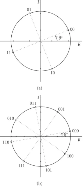
modu-lation diversity order. The mapping rule is given inFigure 2
for QPSK and 8PSK constellations.According to the desired cooperation ratio, users divide their transmissions into two parts as similar to the classical coded cooperation. LetTf,1
andTf,2denote the time intervals of the fth frame,Tf,2/Tf
being the cooperation ratio whereTf = Tf,1+Tf,2, since
the cooperation is realized inTf,2. For a transmission from Ui(i ∈ {1, 2}) duringTf,t(t ∈ {1, 2}), the received signal
sequence at unitj∈ {1, 2,D}can be written as
r(fi j,t)=hf,i js(fi),t+n
(i j)
f,t, (1)
where s(fi),t is the transmitted symbol sequence according to the CICC schemes which will be presented in the next
section, hf,i j is the zero-mean complex Gaussian fading
coefficients with variance 1/2 in each dimension andn(fi j,t)is the AWGN sequence whose zero-mean complex components
have variance N0/2 in each dimension. All complex fading
coefficients are assumed constant during one frame interval
and changing independently from one frame to another. The interuser and user-to-destination channels are assumed independent of each other. All receivers perfectly know
channel fading coefficients, and the interuser channel is
assumed reciprocal, that is,hf,12=hf,21. In the sequel, (·)∗,
(·)T
, and| · |denote transpose conjugate, transpose, and the Euclidean norm, respectively.
2.2. CICC Schemes. In a quasistatic fading channel, CI can be performed between symbols of two consecutive frames to
form the CI symbol sequences since modulation diversity [9]
U2
hf,21
U1
D hf,12
hf,1D
hf,2D
Figure1: Cooperative system model.
θ◦ R I
01
11
10
00
(a)
θ◦ R I
011 010
110
111
101
100 000 001
(b)
Figure 2: θo rotated (a) QPSK and (b) 8PSK symbols and
corresponding bit mappings.
first and second frames, and for simplicity, the decoding processes will be derived forU1, in the sequel.
The coded symbol sequence and its CI version forUiat
thefth frame are denoted byx(fi)andx(fi), respectively, where
f ∈ {1, 2}. Coordinate interleaving process is performed by x1(i) = x
(i) 1R + jx
(i) 2I and x
(i) 2 = x
(i) 2R + jx
(i)
1I, where x
(i)
f R
and x(f Ii) denote real and imaginary parts of the coded
symbol sequencex(fi), respectively. Users divide their symbol sequences x(fi) into unpunctured x(fi)u and puncturedx(fi)p
symbol sequences according to the desired cooperation ratio.
CI versions ofx(fi)u andx(fi)p are denoted by x(fi)uandx(fi)p, respectively.
Two CICC schemes (Schemes A and B) are considered related to the cooperation status unknown or known at the users. The signaling models for Schemes A and B are given in Figures3and4, respectively. Users send CI symbolsx(1i)u
duringT1,1which contain information of the first and second frames. Each symbol can be detected from only its real or imaginary part since, due to the rotation of the signal set,
both real and imaginary parts of the symbols are different
(Figure 2). Therefore, users can detect information bits of the first and second frames based only on the transmission
duringT1,1and decide to cooperate when the CRC bits are
correctly decoded for both frames. Otherwise, they do not cooperate and send their own punctured symbol sequences.
U1 andU2 detect each other’s information bits of the first
and second frames fromx(1iR)u andx(2iI)u transmitted during
T1,1. At the end of the time intervalT1,1, symbol sequence
transmitted fromU1is obtained atU2as
r(12)1,1 =h1,12s (1) 1,1+n
(12)
1,1, (2)
wheres(1)1,1 = x (1)u
1 = x (1)u
1R + jx
(1)u
2I . The following theorem
simplify the metric calculations at the receivers.
Theorem 1. Without deinterleaving process, the symbol
seq-uencesx(1)1Ruandx
(1)u
2I can be separately detected from
x(1)1Ru=arg min
x(1)1Ru
r(12)1,1 −h1,12x (1)u
1R
2
,
x(1)2Iu=arg min
x(1)2Iu
r(12)1,1 −jh1,12x (1)u
2I
2
,
(3)
where minimizations are over all possible values ofx(1)1Ruand x2(1)Iu, respectively.
The proof of this theorem is given in the appendix. Note that, the number of sequences to be considered during
the minimizations in (3) is reduced using the Viterbi
algorithm.
If x(1)1Ruand x(1)2Iu are correctly decided by checking the CRC bits, that is, x1(1)Ru = x(1)1Ru and x(1)2Iu = x2(1)Iu, U2
transmits the punctured CI symbol sequences ofU1inT1,2
andT2,2according to the cooperation schemes. Otherwise,
U2transmits its own punctured CI symbols. Same procedure
is applied forU1. Note that duringT2,1users send their own unpunctured CI symbolsx2(i)u.
According to the users’ decisions to cooperate or not,
four different cooperation cases occur. These cases are
labeled as C1 (both users cooperate), C2 (both users do not
cooperate), C3 (U1 cooperates, U2 does not), and C4 (U2
cooperates, U1 does not) in Figures 3and4. Users send a
cooperation flag bit to broadcast cooperation status at the beginning ofT1,2.
C1
Figure3: Scheme A: users do not know if the other cooperates or not.
C3
Figure4: Scheme B: users know if the other cooperates or not.
performance. To overcome this problem, C3 and C4 are
modified as in Figure 4 assuming that each user knows if
the other cooperates or not by detecting the cooperation flag bit. In these cases, cooperation is performed only at the imaginary part of the symbols and each user sends its own punctured symbols, at the real part. We call this modified scheme as Scheme B, C1, and C2 cases remaining the same for both schemes.
It is assumed that the destination always knows which cooperation case is realized by detecting the cooperation flag
bit. Therefore, the transmitted data fromU1andU2during
the first and second frames can be detected using appropriate decoding metrics for each cooperation case. If the decision
metric for unpunctured symbols ofU1in the first frame is
defined as
according to each cooperation case of Scheme A. For the cases C3 and C4 of Scheme B, decision metrics at the destination are modified as follows:
C3: m(1)1 =m
3. Performance Analysis
Without loss of generality, we consider the transmission of
U1for the performance evaluation and drop the superscript
(1) in the sequel.
3.1. Pairwise Error Probability (PEP) Preliminaries. Let the erroneously detected symbol sequence at the receiver side (partner or destination) beyf whenxf is transmitted, then
the conditional PEP can be expressed as
Pxf −→yf |h
wherehis the channel coefficients vector,Esis the average
symbol energy,N0 is the complex AWGN variance,Q(·) is
GaussianQ-function, andD2
h(xf,yf) is the weighted squared
Euclidean distance betweenxf andyf. Using the inequality
Q(x)≤(1/2)e−x2/2
the squared Euclidean distance between unpunctured and
punctured real parts of xf and yf are expressed as (The
superscript 2 denoting the square is omitted forduf R,d p f R, and
dτf Rto avoid notation complexity.)
duf R=
xuf R−yuf Rxuf R−yuf RT, (9)
dpf R=xpf R−ypf Rxpf R−ypf RT, (10)
respectively. The total squared Euclidean distance for real components is calculated from
dτ
Squared Euclidean distances, for the imaginary parts, can be expressed similar to (9)–(11).
3.2. PEP Upper Bounds for Decisions at the Users. Interuser channel performance is dependent on decoding process at the users. Using the decoding metrics applied at the users in
T1,1given by (3), the weighted squared Euclidean distances used in (7) for the first and second frames are given as
D2
respectively. By taking the expectation of (8) over h =
[h1,12,h2,12], upper bounds on PEP forx1andx2are obtained
respectively. Therefore, the minimum values ofdu1Randd2uI
over all (x1,y1) and (x2,y2) pairs have to be maximized to
increase the interuser channel performance.
3.3. PEP Upper Bounds for Decisions at the Destination.
For the four cooperation cases of Scheme A, the weighted squared Euclidean distances in (7) are expressed as follows:
C1: D2
h2,1D,h2,2D], PEP upper bounds for each cooperation case are
obtained as follows:
Considering Scheme B, the weighted squared Euclidean distances and upper bounds on PEP for cases C3 and C4 are modified, respectively, as follows:
C3: Dh2
upper bounds for the other cases remaining same as given in
(17). Note that the PEP upper bounds for the other frames
can be similarly written as (17) and (18).
Forγ 1, upper bounds on PEP for all cases in both
schemes are approximated by
Px1−→y1
ρ. In (19), the upper bound on PEP is inversely proportional toγη, and thus the diversity order isη. Ifdw
1q=/0 for all (q,w)
pairs of (17), maximum diversity order of four is achieved
for both users when both of them successfully decode each others and cooperate (C1). The diversity order is doubled compared to the nocooperation case (C2), where diversity
order is limited to two coming from CI. In (19), a coding
advantage of(q,w)∈ρ(dw1q) is also achieved.
4. New Code Design Criteria and
Cooperative Trellis Codes
4.1. New Code Design Criteria for CICC. From PEP upper
bounds for CICC schemes given in Figures 3 and 4,
maximum achievable diversity order is four which can be achieved by proper coding in high SNR region. Both users are able to hold this desired diversity order for the case C1. Therefore, the realization percentages of C1 have to be maximized at first. This is our first design criterion which
we call cooperation criterion since both users cooperate in
C1. Maximum diversity order of four is achieved when all squared Euclidean distances related to the PEP upper bound for C1 differ from zero. This is our second design criterion
which corresponds to diversity. Finally, coding gain of the
new codes should be maximized to reach minimum error probability. This is our third and last design criterion named asthe coding advantage.
Code design criteria for CICC can be summarized as follows.
(1)Cooperation Criterion.To achieve the full cooperation case (C1) with maximum percentage of realization,
the minimum values of du
f R and duf I have to be
maximized.
(2)Diversity Criterion.To achieve the maximum diver-sity order of four for C1,du
have to be nonzero.
(3)Coding Advantage Criterion. To achieve maximum
coding advantage for C1, the minimum value of the productduf Rduf Id
p f Rd
p
f I has to be maximized over all
distinct symbol sequences.
Note that the cooperation criterion is related to interuser channel performance, the two others to user-to-destination channel performance.
4.2. Cooperative Trellis Encoder Structure and New Codes (NC). The generic ratek/ncooperative trellis encoder used
in the exhaustive code search is shown in Figure 5, where
bξμ,cζ, and gξμ,ζ are the μth information content of the ξth
shift register, ζth coded bit and μth binary multiplication
coefficient of the ξth shift register and the ζth coded
bit, respectively, (ξ = 1, 2,. . .,k, ζ = 1, 2,. . .,n, μ = 0, 1, 2,. . .,υξ). Hereυξ is the memory order of theξth shift
register. The total memory order of the encoder, denoted
by υ, is obtained from υ = k
ξ=1υξ. The total number
of states for the trellis encoder is 2υ. Multiplier outputs
from all shift registers are added by modulo two, giving
the encoder output. The encoder output forζth coded bit
can be computed as cζ = k
μ(mod2) which
is then pair by pair or triple by triple mapped to rotated QPSK or 8PSK constellation symbols, respectively, as shown in Figure 2. The coded symbols are then divided into unpunctured and punctured parts. The puncturing process can be described as periodically deleting selected symbols from the output of the encoder in each trellis branch. The puncturing rate defined as the ratio of the number of punctured symbols to total number of symbols at a trellis branch, is chosen according to desired cooperation rate.
In this paper, new cooperative trellis codes with optim-ized θo and gξ
μ,ζ values are obtained as given inTable 1 by
extensive computer search over our design criteria. During the computer search process, the optimum rotation angle and the part of code’s generator vector corresponding to the cooperation criterion are obtained by maximizing min{du
f Imin depend on each other when the same
code is used for the two frames between which coordinate interleaving is performed. The remaining part of the generator vector is obtained by maximizing the product
duf Rduf Id p f Rd
p
f I. In Table 1, NC1, NC2, and NC3 represent
the new 4-, 8-, and 16-state cooperative trellis codes for QPSK, respectively. NC4 and NC5 represent the new 8 and 16-state cooperative trellis codes for 8PSK, respectively. In all of these codes parallel transitions are excluded to avoid their restrictive effect on the error performance. The generic rates of these codes are chosen as 2/4 and 3/6 for QPSK and 8PSK, respectively. The generator vectors are defined asgξ =
[(g0,1ξ ,g0,2ξ ,. . .,g0,ξn),(g1,1ξ ,g1,2ξ ,. . .,g1,ξn),. . .,(gυξξ,1,gυξξ,2,. . .,gυξξ,n)],
g0,11 ,g0,21 ,. . .,g0,1n
g1,11 ,g1,21 ,. . .,g1,1n
g1
υ1,1,gυ11,2,. . .,gυ11,n
gυkk,1,g
k υk,2,. . .,g
k υk,n
gk
1,1,g1,2k ,. . .,g1,kn
gk
0,1,g0,2k ,. . .,g0,kn
c1,c2,. . .,cn
b1
0 b11 b1υ1
. . .
. . .
. . . bk0 b1k bkυk
Figure5: Cooperative trellis encoder.
Table1: Generator vectors for cooperative trellis codes.
Codes Modulation k/n υ θo
opt Generator vectors
NC1 QPSK 2/4 2 19 g1=[(0101), (1011)]
g2=[(1111), (0110)]
NC2 QPSK 2/4 3 19 g1=[(1111), (0110)]
g2=[(0101), (1010), (1001)]
NC3 QPSK 2/4 4 19 g1=[(1111), (0111), (0101)]
g2=[(0101), (1001), (1010)]
NC4 8PSK 3/6 3 9
g1=[(110110), (101101)]
g2=[(011011), (111001)]
g3=[(001111), (100010)]
NC5 8PSK 3/6 4 9
g1=[(110110), (101111)]
g2=[(011111), (111001)]
g3=[(001011), (100010), (100010)]
branch of these cooperative code trellisses, coded bits are mapped to two rotated QPSK or 8PSK symbols, first and second ones forming the unpunctured and punctured symbol sequences, respectively. Thus, all new cooperative trellis codes given inTable 1have a cooperation rate of 50%. Best QPSK and 8PSK space-time trellis codes given in
[12] for two transmit antennas in slow fading channels
are considered as reference codes because of having the same coding rates with the new codes and used in the
considered CICC schemes. Optimum rotation angle θo is
also investigated for these reference codes. The parameters of the new and reference codes for QPSK and 8PSK are shown in Tables2and3, respectively. Here,CAminandCCmin
denote the minimum value of the productdu
f Rduf Id p f Rd
p f Iand
min{du f Rmin,d
u
f Imin}, respectively.
5. Performance Results
Throughout the performance evaluation by computer simu-lations, source blocks of 128 and 126 bits including 16 CRC bits with generator polynomial 15935 in hexadecimal form, were considered in each frame for QPSK and 8PSK coopera-tive codes, respeccoopera-tively. We assumed that all channels are qua-sistatic, all receivers perfectly know fading coefficients, the destination always knows which cooperation case is realized, and the interuser channel is reciprocal. Moreover, the users were assumed having statistically similar uplink channels. New designed and reference codes with the parameters given in Tables1,2, and3were considered in the simulations.
Table2: Comparison of new (NC1, NC2, NC3) and reference (V1, V2, V3) QPSK codes.
Codes υ θo
opt ηfor C1 CAmin Multiplicity of
CAmin
CCmin Multiplicity of
CCmin
NC1 2 19 4 16.786 32 0.769 128
NC2 3 19 4 32.475 704 0.808 64
NC3 4 19 4 74.321 1536 1.153 2048
V1 2 19 4 0.941 32 0.384 64
V2 3 19 4 2.299 64 0.384 256
V3 4 19 4 17.611 256 0.769 1536
Table3: Comparison of new (NC4, NC5) and reference (V4, V5) 8PSK codes.
Codes υ θo
opt ηfor C1 CAmin Multiplicity ofCA
min CCmin
Multiplicity of CCmin
NC4 3 9 4 0.739 3616 0.081 256
NC5 4 9 4 1.153 128 0.096 8192
V4 3 9 4 0.009 256 0.032 512
V5 4 9 4 0.000 556 0.000 556
FER
10−6
10−5
10−4
10−3
10−2
10−1
Average received SNR at the destination
10 12 14 16 18 20
V1 V2 V3
NC1 NC2 NC3
Figure6: FER performances of QPSK codes for cooperation case C1.
cooperation case C1. Frame error rate (FER) performance
curves under this assumption are given in Figures6and7for
QPSK and 8PSK codes, respectively. These simulation curves
are consistent with theCAmin values given in Tables 2and
3. In Figure 6, 8-state NC2 code which has approximately two times more coding advantage than the 4-state NC1 code provides a received SNR advantage of 0.5 dB at an FER
value of 10−3. An additional 0.7 dB received SNR advantage
is provided by the 16-state NC3 code which has a good
enhancement inCAmin value. At an FER value of 10−3, the
received SNR advantages of NC1, NC2, and NC3 over V1, V2, and V3 are 2, 1.4, and 0.5 dB, respectively, as expected fromCAminvalues of these codes given inTable 2. Also note
FER
10−5
10−4
10−3
10−2
10−1
100
Average received SNR at the destination
10 12 14 16 18 20
V4 V5
NC4 NC5
Figure7: FER performances of 8PSK codes for cooperation case C1.
from these curves that maximum diversity order of four is
achieved for all codes. In Figure 7, the 16-state NC5 code
which has greater CAmin value and much less multiplicity
than the 8-state NC4 code provides a coding advantage of
2 dB at an FER value of 10−3. Both NC4 and NC5 outperform
the corresponding reference codes V4 and V5 as expected.
Note also that from Figure 7, maximum diversity order of
four is achieved for NC4 and NC5 at high SNR values, while diversity orders of V4 and V5 which have approximately zero CAmin values, degrade as expected from the diversity criterion.
Secondly, we consider decoding errors at the users.
FER
10−5
10−4
10−3
10−2
10−1
Average received SNR at the destination
10 12 14 16 18 20
NC1 scheme A NC1 scheme B NC2 scheme A
NC2 scheme B NC3 scheme A NC3 scheme B
Figure8: FER performances of new QPSK codes for Schemes A and B (dSNR=10 dB).
FER
10−4
10−3
10−2
10−1
100
Average received SNR at the destination
10 12 14 16 18 20
NC4 scheme A NC4 scheme B
NC5 scheme A NC5 scheme B
Figure9: FER performances of new 8PSK codes for Schemes A and B (dSNR=10 dB).
user-to-destination average received SNR and interuser channel SNR (iSNR), was assumed equal to 10 dB during all simulations. The FER performances of new QPSK and 8PSK codes are compared for CICC Schemes A and B in
Figures 8 and 9, respectively. According to Figures 8 and
9, Scheme B provides better performance than Scheme A
for all cooperative codes, as expected. In Figure 8, Scheme
B provides 0.7, 0.8, and 0.9 dB received SNR advantages compared to Scheme A for NC1, NC2, and NC3 at an
FER value of 10−3, respectively. However, for Scheme A,
the coding advantage provided by increasing the trellis
FER
10−5
10−4
10−3
10−2
10−1
Average received SNR at the destination
10 12 14 16 18 20
V1 scheme B V2 scheme B V3 scheme B
NC1 scheme B NC2 scheme B NC3 scheme B
Figure10: FER performances of QPSK codes for Scheme B (dSNR
=10 dB).
FER
10−4
10−3
10−2
10−1
100
Average received SNR at the destination
10 12 14 16 18 20
V4 scheme B V5 scheme B
NC4 scheme B NC5 scheme B
Figure11: FER performances of 8PSK codes for Scheme B (dSNR
=10 dB).
state number is approximately limited to 0.2 dB while it approaches to 0.5 dB for Scheme B. For Scheme A, the coding advantage provided in C1 with the increase of the trellis states is lost when overall system performance is considered, due to the low FER performance in cases C3 and C4. For
8PSK cooperative codes, fromFigure 9, Scheme B provides
0.8 and 1.9 dB received SNR advantages compared to Scheme A for NC4 and NC5 at an FER value of 10−2, respectively. As
Oc
cur
enc
e
p
er
ce
ntages
of
C1
0.65 0.7 0.75 0.8 0.85 0.9 0.95 1
Interuser channel SNR (iSNR)
20 22 24 26 28 30
NC3 NC2 NC1
V3 V2 V1
Figure12: Occurrence percentages of C1 for QPSK codes.
Oc
cur
enc
e
p
er
ce
ntages
of
C1
0 0.1 0.2 0.3 0.4 0.5 0.6 0.7 0.8
Interuser channel SNR (iSNR)
20 22 24 26 28 30
NC5 NC4
V5 V4
Figure13: Occurrence percentages of C1 for 8PSK codes.
and 8PSK codes for CICC Schemes B are obtained as given in Figures10and11, respectively. InFigure 10, the received SNR advantages of NC1, NC2, and NC3 over V1, V2, and V3 are 1.8, 1.6, and 0.5 dB at an FER value of 10−3, respectively.
Both NC4 and NC5 outperform the corresponding reference
codes V4 and V5 as seen in Figure 11. At an FER value
of 10−2, NC4 and NC5 have 1.4 and 4.5 dB received SNR
advantages over V4 and V5. Occurrence percentages of the cooperation case C1 for QPSK and 8PSK codes are given
in Figures12and13, respectively, for iSNR values changing
from 20 to 30 dB. These simulation curves are fully consistent
with the CCmin values given in Tables 2 and 3. Note that
from these curves, occurence percentage of C1 increases with increasing values ofCCmin.
FER
10−5
10−4
10−3
10−2
10−1
Average received SNR at the destination
10 12 14 16 18 20
NC1 [4] NC1 CICC NC2 [4]
NC2 CICC NC3 [4] NC3 CICC
Figure14: Performance comparison of the proposed QPSK codes for classical [4] and CI coded cooperation.
FER
10−4
10−3
10−2
10−1
100
Average received SNR at the destination
10 12 14 16 18 20
NC4 [4] NC4 CICC
NC5 [4] NC5 CICC
Figure15: Performance comparison of the proposed 8PSK codes for classical [4] and CI coded cooperation.
Finally, we compare performances of the proposed QPSK
and 8PSK codes for classical [4] and CI coded cooperation
in Figures 14 and 15, respectively. It is obvious that the
proposed CICC technique reaches maximum diversity order of four at high SNR values while classical one has maximum diversity order of two. Due to the diversity gain, proposed CICC technique provides approximately 5.5 dB received SNR advantage against classical one for all QPSK codes (NC1,
NC2, and NC3) at an FER value of 10−3. For 8PSK codes
(NC4 and NC5), the received SNR advantages of CICC
respectively. Since occurrence percentages of the cooperation case C1 for 8PSK codes are not as much as for QPSK codes, 8PSK codes exhibit lower diversity order and therefore lower received SNR advantage than QPSK codes for the considered SNR ranges.
6. Conclusion
In this paper, a two-user cooperative communication scheme, which combines coded cooperation and modulation diversity techniques, has been proposed for wireless commu-nication systems. Two times more diversity has been achieved compared to the pure coded cooperation scheme, due to the fact that the proposed system takes full advantage of both the cooperation and modulation diversities. New code design criteria have been derived for CICC systems, and cooperative trellis codes for QPSK and 8PSK have been obtained by exhaustive computer search. The new codes have better error performance than the corresponding best space-time codes used in cooperation with CI, which shows that the best space-time trellis codes given in literature are not the best codes for the CICC systems.
Appendix
Proof ofTheorem 1.For (2), maximum likelihood (ML) de-tection metric can be written as
r(12)1,1 −h1,12
x(1)1Ru+jx
(1)u
2I
2
. (A.1)
By deleting the terms which are independent of x(1)1Ru and
x2(1)Iu, (A.1) can be rewritten as h1,122
x(1)1Ru
2
+x(1)2Iu
2
−h1,12x(1)1Ru+jx
(1)u
2I
r(12)1,1
∗
−r(12)1,1 h∗1,12
x(1)1Ru−jx
(1)u
2I
T
, (A.2)
which can be decomposed into two parts, where h1,122
x1(1)Ru2−h1,12x1(1)Rur(12)1,1∗−r(12)1,1h∗1,12
x(1)1RuT
(A.3)
is only function ofx(1)1Ru, and
h1,122
x(1)2Iu
2
−jh1,12x(1)2Iu
r(12)1,1
∗
+jr(12)1,1h∗1,12
x(1)2Iu
T
(A.4)
is only function ofx(1)2Iu. Equations (A.3) and (A.4) can be
finally modified as
r(12)1,1 −h1,12x (1)u
1R
2
, (A.5)
r(12)1,1 −jh1,12x (1)u
2I
2
, (A.6)
respectively, since|r(12)1,1 | 2
is independent ofx(1)1Ruandx2(1)Iu.
Therefore, to minimize (A.1) we can minimize (A.5) and
(A.6) separately for detecting x(1)1Ru and x(1) u
2I , respectively.
These are simple and unique decoding metrics which can be used without deinterleaving process at the receiver side.
Acknowledgment
This work was supported by the Scientific and Technological Research Council of Turkey TUBITAK, Project no. 107E022.
References
[1] A. Sendonaris, E. Erkip, and B. Aazhang, “Increasing uplink capacity via user cooperation diversity,” in Proceedings of IEEE International Symposium on Information Theory, p. 156, Cambridge, Mass, USA, August 1998.
[2] J. N. Laneman,Cooperative diversity in wireless networks: algo-rithms and architectures, Ph.D. thesis, Massachusetts Institute of Technology, Cambridge, Mass, USA, 2002.
[3] T. E. Hunter and A. Nosratinia, “Coded cooperation under slow fading, fast fading, and power control,” inProceedings of the 36th Asilomar Conference on Signals, Systems and Computers, vol. 1, pp. 118–122, November 2002.
[4] T. E. Hunter and A. Nosratinia, “Diversity through coded cooperation,”IEEE Transactions on Wireless Communications, vol. 5, no. 2, pp. 283–289, 2006.
[5] K. Ho-Van and T. Le-Ngoc, “A bandwidth-efficient coded user-cooperation scheme for flat block fading channels,” in
Proceedings of the 4th IEEE Internatilonal Symposium on Wireless Communication Systems (ISWCS ’07), pp. 421–425, October 2007.
[6] J. Li and A. Stefanov, “Cooperative multiple trellis coded modulation,” inProceedings of IEEE Military Communications Conference (MILCOM ’06), pp. 1–6, Washington, DC, USA, October 2006.
[7] J. Li and A. Stefanov, “General design criteria and properties of cooperative MTCM systems,” inProceedings of IEEE Global Telecommunications Conference (GLOBECOM ’07), pp. 3432– 3436, November 2007.
[8] G. Taricco and E. Viterbo, “Performance of component interleaved signal sets for fading channels,”Electronics Letters, vol. 32, no. 13, pp. 1170–1172, 1996.
[9] J. Boutros and E. Viterbo, “Signal space diversity: a power-and bpower-andwidth-efficient diversity technique for the Rayleigh fading channel,”IEEE Transactions on Information Theory, vol. 44, no. 4, pp. 1453–1467, 1998.
[10] M. Z. A. Khan and B. S. Rajan, “Single-symbol maximum likelihood decodable linear STBCs,” IEEE Transactions on Information Theory, vol. 52, no. 5, pp. 2062–2091, 2006. [11] J. Harshan and B. S. Rajan, “Coordinate interleaved
dis-tributed space-time coding for two-antenna-relays networks,” inProceedings of IEEE Global Telecommunications Conference (GLOBECOM ’07), pp. 1719–1723, November 2007.