ISSN(Online) : 2319-8753 ISSN (Print) : 2347-6710
I
nternational
J
ournal of
I
nnovative
R
esearch in
S
cience,
E
ngineering and
T
echnology
(An ISO 3297: 2007 Certified Organization)
Website: www.ijirset.com Vol. 6, Issue 6, June 2017
Comparative Study of Diagrid, Simple Frame
and Various Bracing Systems
Viraj Baile1, Dr. A.A. Bage2
M. Tech Student, Dept. of Structural Engineering, Sardar Patel College of Engineering, Andheri, Maharashtra, India1
Associate Professor, Dept. of Structural Engineering, Sardar Patel College of Engineering, Andheri,
Maharashtra, India 2
ABSTRACT:Diagrid Structure is one of the most unique structural systems that has been developed in recent years. For designing tall buildings there are various structural systems such as moment resisting frame, shear wall system, bracing system, space trusses, tubular structures etc. Diagrid is one of the new structural systems which is adept for designing tall buildings. In this paper, a comparative study between diagrid system, simple frame system and bracing system has been put forth. A 36-storeyed diagrid building, simple frame building and a building with various bracing systems have been modelled and analysed. The bracing systems are X-type, V-type and Inverted V- type. The positions of the bracings have also been varied. A total of 15 buildings have been modelled and analysed to compare which system performs better a lateral load resisting system. The modelling and analysis has been performed on ETABS. The dynamic analysis is performed by using Response Spectrum Method. All the loadings and the checks are provided as per Indian Standards.
KEYWORDS:Bracing systems, Comparative study, Dynamic analysis, Diagrid structures, Tall structures.
I. INTRODUCTION
Designing tall buildings has become a necessity due to increase in population, scarcity of land and environmental issues. The desire for aesthetics in urban settings and human aspiration to build higher also contribute for the same. Thus, this has led to development and evolution of many structural systems. Some of the structural systems used for designing of tall buildings are shear wall system, rigid frame, moment frame system, braced frame system, outrigger system, core structure system, tubular structures, bundled tube, frame tube system, diagrid system etc. The main reason for developing these systems is to effectively increase the lateral load resisting capacity of the structure while maintaining the economy because for tall structures the governing factor is lateral loads contributed by wind (earthquake load is also factored in but for tall structures wind plays the dominant role). In this paper following lateral load resisting systems have been analysed and compared:
1. Simple Frame Structure (Moment Resisting Frame): In this system, the lateral forces generated and primarily
resisted by rigid frame action i.e. by development of shear force and bending moment in joints and frame members. The rigidity of joints and frame itself is the source of lateral stiffness in the structure.
2. Braced Frame Structure: In this system, bracings are provided to resist the lateral forces. Bracings are designed
Fig 1: Braced Frame Structures
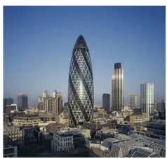
3. Diagrid Structure: Diagrid structural system is a perimeter frame structure made up of diagonal members which
form a diamond shaped element that inherits triangular module or configuration. The RC core acts as a cantilever and the diagrid resists the shear and thus acting together increasing the stiffness of the structure. The main advantage of this system is that is more efficient at resisting lateral loads than other systems. Other advantages of this systems include redundancy i.e. it can transfer the load from a failed portion of the structure to another, it consumes less amount of steel, it has column free exterior, it has no need of providing façade, it has high degree of aesthetics and beauty.
Aldar Headquarters, Qatar Hearst Tower, New York Swiss Re Building, London
Fig 2: Diagrid Structures
II. RELATED WORK
Since diagrid is relatively a new structural system, the research work done or available is quite limited.The main source for any data available for diagrid is from the diagrid buildings that have been constructed and there are only handful of them in the whole world.Even though few researchers have extensively studied this new system and put forth their findings, it is not enough for any guidelines to be established for designing a diagrid structure.Hence any new research work done on diagrid is helpful in aiding to understand the working and usability if this new structural system. The current research done on diagrid includes, diagrid being compared with conventional systems, pushover analysis performed on diagrid building, finding the optimum angle for diagrid.
ISSN(Online) : 2319-8753 ISSN (Print) : 2347-6710
I
nternational
J
ournal of
I
nnovative
R
esearch in
S
cience,
E
ngineering and
T
echnology
(An ISO 3297: 2007 Certified Organization)
Website: www.ijirset.com Vol. 6, Issue 6, June 2017
diagrid steel frame building. In a paper published by Manthan I Shah in IJERA he analysed and compareda 18x18 m conventional and diagrid steel frame building.
III. OJECTIVE OF THE PROJECT
The main objectives in this paper are:
To study different type of bracings and identify which type is better.
To find out which is the optimum position for the bracings.
To analyse and compare simple frame, bracing frame and diagrid structure.
IV. MODELLINGANDANALYSIS
A total number of 14 models have been analysed, 13 of which are of various bracing systems with different positioning, one is a simple frame structure and one is a diagrid structure. The modelling and the analysis is performed in ETABS and response spectrum method has been utilized for dynamic analysis. Following are the details of the models:
Table 2: Load Cases used in Analysis
Table 1: Details of Structure
For bracing systems X-type, V-type and Inverted V-type bracings were used. The position of bracing has also been varied to study its effect and find out optimum position for the same. Section ISA 200x200x15 has been used for all types of bracings. Bracings have been provided in the form of one bay, 2 bay and over entire face in elevation.
For diagrid structure steel pipe sections have been utilized as diagrids. The size of sections reduces as they are placed in higher storeys i.e. heavier diagrid sections were used in bottom storeys and as the storeys increased lighter diagrid sections were used. The dimensions of the steel pipe diagrid sections used are as follows: 400 mm diameter and 18 mm thick and similarly 400x15 mm, 350x15mm, 300x15mm and 250x15 mm.
Plan (18x18) mm
Number of Storeys 36
Floor to Floor Height 3.6 m
Structure Utility Office/Commercial
Seismic Zone V
Seismic Coefficient 0.36
Response Reduction Factor 5
Importance Factor 1
Wind Speed 44 m/s
Structure Type C
Dead Load 4 Kn/m
Live Load 4 Kn/m
Load On Beams 14.628 Kn
Analysis Method Dynamic Analysis (RSM)
Codes Used
IS 1893 Part 1 IS 875 IS 456 & IS 800
LOAD CASES
1) 1.7 (DL + IL) 2) 1.7 (DL + EL) 3) 1.7 (DL - EL) 4) 1.3 (DL + lL + EL)
5) 1.3 (DL + lL - EL) 6) 1.5 (DL + lL) 7) 1.2 (DL+IL+EL) 8) 1.2 (DL + IL- EL)
Fig 3: Plan for Simple frame and Fig 4: Plan for Diagrid Structure Braced frame Structure
By comparing Fig 3 and Fig 4, diagrid structure has few columns compared to simple frame and braced frame structure. Diagrid structure has almost column free exterior and interior except for core.
ISSN(Online) : 2319-8753 ISSN (Print) : 2347-6710
I
nternational
J
ournal of
I
nnovative
R
esearch in
S
cience,
E
ngineering and
T
echnology
(An ISO 3297: 2007 Certified Organization)
Website: www.ijirset.com Vol. 6, Issue 6, June 2017
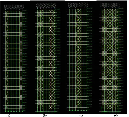
Fig 5 shows the elevation of type braced structures with different position of braces. Fig 5(a) shows single bay X-type brace at the ends/corners, Fig 5(b) shows two bay X-X-type brace at the ends/corners, Fig 5(c) shows X-X-type brace at the middle and Fig 5(d) shows X-type brace over entire face of structure in elevation.
Similarly, models for V-type braced structures and Inverted V-type braced structures have been modelled and analysed.
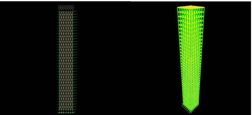
Fig 6: Elevation of Diagrid Structure Fig 7: 3D View of Simple Frame Structure
V. RESULTS
Following is the Legend used to express the results:
BS+IV+END+1 Single Bay Inverted V type Bracing at Ends
BS+IV+END+2 Two Bay Inverted V type Bracing at Ends
BS+IV+MIDDLE Two Bay Inverted V type Bracing at Middle
BS+IV+ENTIRE Inverted IV type Bracing over entire face in Elevation
BS+V+END+1 Single Bay V type Bracing at Ends
BS+V+END+2 Two Bay V type Bracing at Ends
BS+V+MIDDLE Two Bay Inverted IV type Bracing at Middle
BS+V+ENTIRE Inverted V type Bracing over entire face in Elevation
BS+X+END+1 Single Bay X type Bracing at Ends
BS+X+END+2 Two Bay X type Bracing at Ends
BS+X+MIDDLE Two Bay X type Bracing at Middle
BS+X+ENTIRE Inverted X type Bracing over entire face in Elevation
SIMPLE FRAME Simple Frame Structure
DIAGRID Diagrid Structure
Maximum Lateral Displacement:
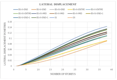
Fig 8: Graph of Lateral Displacementsof models with Lateral Displacements in metres on Y axis and Number of Storeys on X axis
From the above figure 8, simple frame structure has the highest lateral displacement and diagrid structure has the least lateral displacement. Amongst the three bracing types, the X-type bracing has the least lateral displacement and thus it can be concluded that X-type bracing is better out of the three bracings presented in this paper. X-type bracing system provided over the entire face in the elevation has lateral displacement closest to that of diagrid structure thus theoretically making it best system for providing bracings but it practically not feasible or rather it’s aesthetically undesirable to provide bracings over entire face of building. Hence the two bay X-type bracing system provided at the ends /corners is the best option for providing bracings in a bracing system.
0 0.02 0.04 0.06 0.08 0.1 0.12 0.14 0.16
0 5 1 0 1 5 2 0 2 5 3 0 3 5 4 0
L
A
T
E
R
A
L
D
IS
P
L
A
CE
M
E
N
T
IN
M
E
T
R
E
S
NUMBER OF STOREYS
L A T E R A L D I S P L A C E M E N T
BS+X+END BS+V+END BS+IV+END BS+X+ENTIRE BS+V+ENTIRE
BS+IV+ENTIRE BS+IV+MID BS+V+MID BS+X+MID BS+IV+END+1
ISSN(Online) : 2319-8753 ISSN (Print) : 2347-6710
I
nternational
J
ournal of
I
nnovative
R
esearch in
S
cience,
E
ngineering and
T
echnology
(An ISO 3297: 2007 Certified Organization)
Website: www.ijirset.com Vol. 6, Issue 6, June 2017
Maximum Storey Drift:
Fig 9: Graph of Storey Drift of models with Storey Drift in metres on Y axis and Number of Storeys on X axis
Time Period:
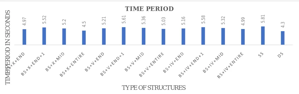
Fig 10: Graph of Time Period of Models with Time Period in seconds on Y axis and Type of Structures on X axis
From Fig 9, diagrid structure has the least storey drift amongst all the models followed by BS+X+ENTIRE, which is the similar pattern seen from lateral displacement.
From Fig 10, diagrid structure has the least time period thus indicating that it has the highest stiffness, hence it can be inferred that diagrid has the highest lateral load resisting/carrying capacity which in turn results in least lateral displacement and least storey drift.
0 0.0002 0.0004 0.0006 0.0008 0.001
0 5 1 0 1 5 2 0 2 5 3 0 3 5 4 0
S T O R E Y D R IF T IN M E T R E S
NUMBER OF STOREYS
S T O R E Y D R I F T
BS+IV+END+1 BS+IV+END+2 BS+IV+MIDDLE BS+IV+ENTIRE BS+V+END+1
BS+V+END+2 BS+V+MIDDLE BS+V+ENTIRE BS+X+END+1 BS+X+END+2
BS+X+MIDDLE BS+X+ENTIRE SIMPLE FRAME DIAGRID
4 .9 7 5 .5 2 5 .2 4
.5 5.2
1 5 .6 1 5 .3 6 5 .0 3 5 .1 6 5 .5 8 5 .3 2 4 .9 9 5 .8 1 4 .3 T IM E P E R IO D IN S E CO N D S
TYPE OF STRUCTURES
TYPE OF STRUCTURE
MAX LATERAL DISP IN METRE
MAX DRIFT IN METRE
BASE SHEAR IN KN
TIME PERIOD IN SECONDS
BS+IV+END+1 0.1339 0.000516 4395592.463 4.97
BS+IV+END+2 0.1163 0.000699 4377255.405 5.52
BS+IV+MIDDLE 0.1222 0.000598 4377255.405 5.2
BS+IV+ENTIRE 0.1088 0.000413 4382693.072 4.5
BS+V+END+1 0.1351 0.000587 4389616.633 5.21
BS+V+END+2 0.1185 0.000724 4374179.175 5.61
BS+V+MIDDLE 0.1241 0.000647 4374179.175 5.36
BS+V+ENTIRE 0.1106 0.000548 4378704.618 5.03
BS+X+END+1 0.1313 0.000577 4389440.003 5.16
BS+X+END+2 0.109 0.000718 4374179.175 5.58
BS+X+MIDDLE 0.1176 0.000639 4374391.131 5.32
BS+X+ENTIRE 0.0922 0.000541 4378704.618 4.99
SIMPLE FRAME 0.1437 0.000804 4358918.347 5.81
DIAGRID 0.091 0.000314 3435877.803 4.3
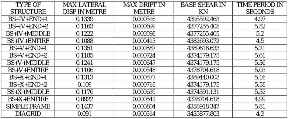
Table 4: Comparison of all Models with different parameters
Maximum permissible lateral displacement is 0.2664 m and maximum permissible storey drift is 0.5328 m. So, all the structures pass the permissible limits.
Amongst the bracing systems, the X-type bracing system is superior than other two types as it can be seen from the maximum lateral displacement and storey drift.
Similarly, by observing the maximum lateral displacement and maximum storey drift it can be seen that 2 bays at the end is the better configuration as providing bracing over entire face in elevation is practically not desirable for economic and aesthetic reasons
From observing the lateral displacements and storey drift it is seen that diagrid structure has the least lateral displacement and storey drift and hence it is far better than any bracing systems at resisting lateral loads.
The time period of diagrid structure is the least suggesting that it has higher stiffness compared to other structures. The base shear is least for diagrid structure thus indicating that it is lighter structure than other. A higher base shear indicates either of the three: 1) Highly Stiff Structure 2) Very Heavy Structure & 3) Location near fault. Since all the models are analysed for same seismic zone the third reason is invalid in this case. From the lower time period, it has already been established that diagrid has higher stiffness. So, the lower base shear value indicates that the diagrid structure is light as compared to other structures thus implying it is more economical.
VI. CONCLUSION
From the analysis results and comparative study put forth in this paper following set of conclusions can be made:
Diagrid Structure overall performs better as lateral load resisting system than bracing systems.
Diagrid Structure has least Maximum Lateral Displacement and Maximum Storey Drift.
Diagrid Structure has higher stiffness than other models.
Diagrid Structure is lighter than other models and thus more economical
X-type Bracings is best out of the three that have been presented in the paper
ISSN(Online) : 2319-8753 ISSN (Print) : 2347-6710
I
nternational
J
ournal of
I
nnovative
R
esearch in
S
cience,
E
ngineering and
T
echnology
(An ISO 3297: 2007 Certified Organization)
Website: www.ijirset.com Vol. 6, Issue 6, June 2017
REFERENCES
[1] Barry Charnish and Terry Mc Donnell “The bow: unique Diagrid Structural System for Sustainable Tall Buildings”, CTBUH 8th World Congress 2008.
[2] Moon, K., Connor, J., and Fernandez, J., “Diagrid Structural System for Tall buildings: Characteristics and Methodology for Preliminary Design”, The structural design of tall and special buildings, Vol. 16, pp.205-230, 2007.
[3] Moon, K. S. (2008). “Material Saving Design Strategies for Tall Buildings”. CTBUH 8th World Congress.
[4] Kyoung, Sun Moon. “Diagrid Structures for Complex-Shaped Tall Buildings.” Procedia Engineering,2011: 1343-1350. [5] Kyoung, Sun Moon. “Diagrid Structures for Complex-Shaped Tall Buildings.” Advanced Materials Research, 2012: 1489-1492. [6] Raghunath.D. Deshpande, Sadanand M. Patil, SubramanyaRatan, “Analysis and Comparison of Diagrid andConventional Structural System”, International Research Journal Engineering and Technology (IRJET) Volume: 02 Issue: 03 |June -2015.
[7] Manthan I. Shah, Snehal V. Mevada, Vishal B. Patel, “Comparative Study of Diagrid Structures with Conventional Frame Structures”, International Journal of Engineering Research and Applications(IJERA) ISSN: 2248-9622, Vol. 6, Issue 5, (Part - 2) May 2016, pp. 22-29. [8] IS: 456-2000. Plain and Reinforced Concrete- Code of Practice (Fourth Revision), Bureau of Indian Standard, New Delhi.