Analysis of Pressure Vessel for Different Wall
Thickness Using FEA
Neelappagowda Jagali1, Santosh Kiragat1, Arun S K2,Mahendramani G3
1
Assistant Professor, Department of Mechanical Engineering, Yellamma Dasappa Institute of Technology Bengaluru,
Karnataka, India.
2
Assistant Professor, Department of Mechanical Engineering, NallaNarasimha Reddy School of Engineering,
Hyderabad, Telangana, India.
3
Associate Professor, Department of Mechanical Engineering, Government Engineering College, Ramanagara,
Karnataka, India.
ABSTRACT: Barrels can be utilized as a multipurpose compartment as it can store gas and also liquid and it can be
utilized as a part of vehicles, home and processing plants. These are intended to store gas, since gas is a compressible liquid it can hold more liters of gas with higher weight which prompts blasting of chamber harming the framework or notwithstanding and bringing about wounds to the general population around it. Thus, appropriate configuration weight must be proposed keeping in mind the end goal to dodge this sort of harms. In this, to anticipate, endeavor is made to check the real limit of the barrel (liters) and blasting weight. The study delivers the system to decide the burst weight of the cylindrical chamber utilizing acceptance technique [1]. As the blasting is a nonlinear conducting material, non-linearity is considered to gauge the burst weight and disappointment area. The attempt has been made using Finite Element Analysis (FEA)for analysis of pressure vessel for different wall thickness to find the failure at the burst pressure using experimental data from the literature and validated.
KEYWORDS: Pressure vessel, Burst pressure, Cylinder, FEA.
I. INTRODUCTION
A pressure vessel is a container designed to store liquids or gases at a particular pressure substantially different from the ambient pressure.[1, 3] The pressure vessels are of different sizes and shapes which depend on the requirement, amount of pressure to withstand and to install (vertical and horizontal). The pressure differential in a pressure vessel is dangerous and fatal accidents may occur in pressure vessel development and operation. Consequently, pressure vessels are designed and manufactured as per the pressure vessel code (ASME Code) and operational engineering authorities backed by legislation driven by standard procedure and formalities [3]. For these reasons, the standards of a pressure vessel varies and involves parameters such as maximum safe operating pressure and temperature, and are engineered with a safety factor, corrosion allowance, minimum design temperature (for brittle fracture).
The usually preferred test for any pressure vessel is hydrostatic testing because of its much safer method of testing as it releases lesser energy if fracture takes place (water does not rapidly increase its volume while rapid depressurization occurs, unlike gases). The vessels over a certain size with internal pressure be built as per ASME Boiler and Pressure Vessel Code [4], these vessels also require an Authorized Inspector to sign off on every new vessel constructed and each vessel has a name plate with pertinent information about the vessel such as maximum allowable working pressure, maximum temperature, minimum design metal temperature, name of the manufacturing company, the date of manufacturing, it's registration number, and ASME's official stamp and code for pressure vessels (U-stamp), making the vessel traceable and officially an American Society Of Mechanical Engineers (ASME)Code vessel [2].Usman Tariq Murtaza et al, published paper on “Design by Analysis versus Design by Formula of a PWR Reactor Pressure Vessel”, the application of the ‘design by analysis’ allows removing the unnecessary conservation caused by applying the ‘design by formula’ approach. An increase of 17.70 % in the maximum allowable pressure is recommended when RPV is designed using the rules of ‘design by analysis’ instead of ‘design by formula’[6].
Theoretically, a spherical pressure vessel has approximately twice the strength of a cylindrical pressure vessel with the same wall thickness and is the ideal shape to hold internal pressure [3]. However, a spherical shape is difficult to manufacture, and therefore more expensive, the most pressure vessels are cylindrical with 2:1 semi-elliptical heads or end caps on each end. Smaller pressure vessels are assembled from a pipe and two covers. For cylindrical vessels with a diameter up to 600 mm, it is possible to use seamless pipe for the shell, thus avoiding many inspection and testing issues. The disadvantage of these vessels is that, greater diameters are more expensive.
In the present investigation, it is proposed to carry out the non-linear transient structural analysis of pressure vesselfor different wall thickness using finite element analysis to evaluate burst pressure of Low Pressure Gas cylinder using the experimental data from the literature.
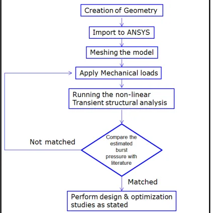
II. METHODOLOGY
The detailed methodology of non-linear transient structural analysis carried out is shown in the Fig.1 in the form of flow chart.
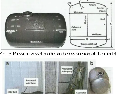
The dimensions of the pressure vessel used for the experimentation is shown in the Fig. 2. The experimental set up to analyze the bursting pressure of cylindersalong with the failed cylinders is shown in the Fig. 3.The experimental values of bursting pressure for 35lt tank of the pressure vessels are given in the Table 1.
Fig. 2: Pressure vessel model and cross section of the model.
Fig. 3: Experimental Setup with Failed Cylinders.
Table 1:Experimental Results for Different Pressure.
Sl.
No. Tank Capacity
(lts)
Nominal Thickness (mm)
Burst Pressure (expt.) MPa
1 35 2.5 9.07
A. Finite Element Analysis
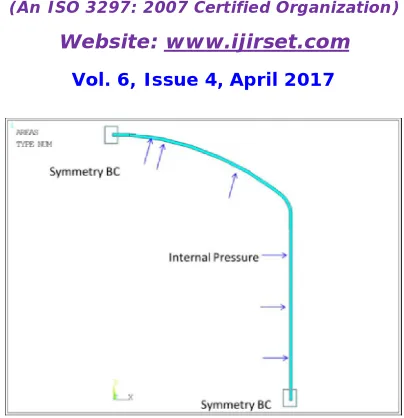
The dimensions of cylinder created with internal diameter of 310mm and thickness of thickness of 2.5mm, and young’s modulus of 104GPa has been used. The FEA results have to validated, the measurement of stresses by the experimental method is necessary.Finite element analysis is an extremely powerful tool for pressure vessel analysis [5].
Fig. 4: Finite Element Model with Boundary Conditions.
III. RESULTS AND DISCUSSION
The finite element analysis has been carried out on pressure vessel in order to find the burst pressure for different thickness at which the pressure vessel fails. The capacity of 35lt tank was considered for the analysis. The maximum deformation occurs at the middle of the cylinder which is sensible as shown in the Fig. 5. As per the experimentation the bursting crack was also observed at the same location as shown in the Fig. 3.
Fig. 5: Failure mode of pressure vessel.
Table 2: Results Comparison for 35lts and 60lts Cylinder.
Sl. No.
Tank Capacity
(lts)
Nominal Thickness
(mm)
Burst Pressure (bar) % error Expt. Simulation
1 35 2.5 90.7 96.675 6.2
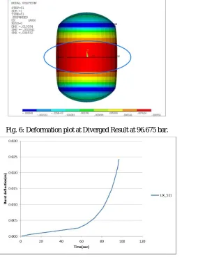
It can be observed from Graph 1 that, the elastic behavior can be seen up to 96.6bar. After 96.6bar, huge increase in deformation can be observed for every 1bar increase in pressure because of the plasticity behavior and fails at 97bar.
Fig. 6: Deformation plot at Diverged Result at 96.675 bar.
Graph 1: Burst Deflection vs. Time Graph.
From the above section it is clear the experimental and FEA results are closely matching, we can adopt the same boundary condition and principles from the FEA analysis for the coming iterations.
Iteration-01:-In this iteration the thickness of the cylinder is changed from 2.5mm (baseline model) to 1.8mm thick.
From the FE result Fig. 7, it is seen that max deformation occurs at the midpoint of the cylinder which is sensible and the crack can be seen at this location.
Fig. 7: Deformation plot at Diverged Result at 61bar.
Graph 2: Burst Deflection vs. Time Graph.
Iteration-02:-In this iteration the thickness of the cylinder is changed from 2.5mm (baseline model) to 3.2mm
thick.From the FE result Fig. 8, it is seen that max deformation occurs at the midpoint of the cylinder which is sensible and the crack can be seen at this location.
Fig. 8: Deformation plot at Diverged Result at 144 bar.
Graph 3: Burst Deflection vs. Time Graph.
Fig. 9: Thickness vs. Burst Pressure Graph.
From analysis it can beobserved that, the increase in thickness, the burst pressure increases. The increase is in cubic and the correlation between thickness of cylinder (x) in mmand burst pressure (y) in bar is given in the Eq.1.
Y=0.0009*x3+0.035*x2+2.1063*x+6.6868 ---Eq.1
IV. CONCLUSIONS
From finite element analysis it can be concluded that, with increase in thickness, the burst pressure increases. The increase burst pressure is in cubic and the correlation between thickness of cylinder and burst pressure is established.
REFERENCES
1. MullaNiyamat et al, “Design and Stress Analysis of Pressure Vessel by Using Ansys”, IJESRT, 4(7), July-2015. 2. SandeepGond et al, “Design and Analysis of the Pressure Vessel”, IJSER, Vol-5, Issue-4, April-2014.
3. Ahmed Ibrahim et al, “Stress Analysis of Thin-Walled Pressure Vessels”, Modern Mechanical Engineering, 2015, 5, 1-9.
4. ASME Boiler and Pressure Vessel Code, Section III, Division 1: Rules for construction of nuclear facility componenets, New York, 2010. 5. DigvijayKolekar et al, published paper on “Stress Analysis of Pressure Vessel with Different Type of End Connections by FEA”, IJIRSET,
Vol-4, Issue-5.
6. Usman Tariq Murtaza et al, “Design by Analysis versus Design by Formula of a PWR Reactor Pressure Vessel”, IMCECS, Vol II, March 18-20, 2015.
7. M. J. Hyder and M. Asif, "Optimization of location and size of opening in a pressure vessel cylinder using ANSYS", Engineering Failure Analysis, vol. 15, pp. 1-19, 2008.
8. BandarupalliPraneeth et al, “Finite Element Analysis of Pressure Vessel and Piping Design”, IJETT, Vol-3, Issue-5, pg 567-570. 9. R. K. Jain, Machine Design, Third ed. Dehli: Khanna Publications, 1983.
10. M. J. Hyder and M. Asif, "Optimization of location and size of opening in a pressure vessel cylinder using ANSYS", Engineering Failure Analysis, vol. 15, pp. 1-19, 2008.
11. Apurva R. Pendbhaje et al, “Design and Analysis of Pressure Vessel”, IJIRTS, Vol-2, No-3.