ISSN(Online): 2319-8753 ISSN (Print): 2347-6710
I
nternational
J
ournal of
I
nnovative
R
esearch in
S
cience,
E
ngineering and
T
echnology
(An ISO 3297: 2007 Certified Organization)
Website: www.ijirset.com
Vol. 6, Issue 7, July 2017
Analysis of Electric Current Density on the
Tip of Pacemaker Electrode
Sapna Jain1, Nisha Raheja2
P.G. Student, Department of Electronics and Communication Engineering, OM Institute of Engineering and
Technology, Hisar, Haryana, India1
Assistant Professor, Department of Electronics and Communication Engineering, OM Institute of Engineering and
Technology, Hisar, Haryana, India2
ABSTRACT: Pacemaker is a medical device placed in chest to help control abnormal heart rhythms. Its main components consist of pulse Generator, battery, leads and electrodes. The electrode is a non insulated termination of the lead which is in direct contact with the heart. The geometry of electrode is studied using COMSOL Tool based on FEM. FEM is a numerical method for solving the problems of engineering and mathematical physics. In this work we have analyzed the effect on electric current density if the spacing between cathode and anode is changed. By modelling pacemaker electrode in COMSOL we can obtain the desired value of electric current density depending on the tissue tolerance.
KEYWORDS: Spherical electrode, Spacing, Current density, Counter electrode
I. INTRODUCTION
Arrhythmias are due to cardiac problems producing abnormal heart rhythms. In general arrhythmias reduce hemodynamic performance including situations where the heart's natural pacemaker develops an abnormal rate or rhythm or when normal conduction pathways are interrupted and a different part of the heart takes over control of the rhythm. An arrhythmia can involve an abnormal rhythm increase (tachycardia; > 100 bpm) or decrease (bradycardia; < 60 bpm), or may be characterized by an irregular cardiac rhythm, e.g. due to asynchrony of the cardiac chambers. An "artificial pacemaker" can restore synchrony between the aria and ventricles. The electrical impulse for stimulating electric pulse in the heart is provided by an implantable pacemaker electrode. Leads which connect pulse generator and electrode are of two types. A unipolar lead system has a single isolated conductor with an electrode located at the tip. A bipolar lead has two separate and isolated conductors connecting the two electrodes, i.e. the anode and cathode, usually not more than 12 mm apart. The cathode refers to the electrode serving as the negative pole for delivering the stimulation pulse and the anode to the positive pole. For unipolar pacing-sensing systems, the distance between anode and cathode easily exceeds 10 cm. Its cathode is typically located at the lead tip whereas the pulse generator housing, usually located in the pectoral region, is used as anode. [1]
II. MODELING OF PACEMAKER ELECTRODE
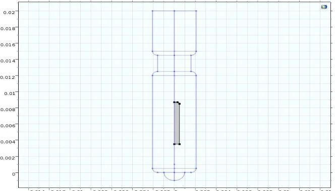
Fig 1:2D geometry of electrode showing spacing between counter and working electrode
ISSN(Online): 2319-8753 ISSN (Print): 2347-6710
I
nternational
J
ournal of
I
nnovative
R
esearch in
S
cience,
E
ngineering and
T
echnology
(An ISO 3297: 2007 Certified Organization)
Website: www.ijirset.com
Vol. 6, Issue 7, July 2017
The rectangle highlighted in the above figure forms the tines of the electrode. The type of lead used in this model is passive fixation lead with tines. The tines hold the pacemaker in its position and reduce the chances of dislodgement. [4]
Fig 3: Passive fixation lead with tines
The above figure shows a passive fixation lead which has tines. Passive ventricular leads have significantly lower pacing thresholds and may potentially prolong estimated battery life by 2 years. [6]
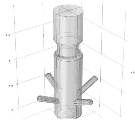
Fig 5: Solid Cylinder around electrode
The outer boundaries are placed far enough from the electrode to give a small impact on the current and potential distribution in COMSOL Multiphysics. [5]
III. SIMULATION RESULTS
ISSN(Online): 2319-8753 ISSN (Print): 2347-6710
I
nternational
J
ournal of
I
nnovative
R
esearch in
S
cience,
E
ngineering and
T
echnology
(An ISO 3297: 2007 Certified Organization)
Website: www.ijirset.com
Vol. 6, Issue 7, July 2017
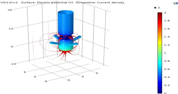
Fig 7: Streamline Plot with Distance between two electrodes is 10.5mm
The above figures 6 and 7 show spacing or distance between working and counter electrode is 14.5mm and 10.5mm respectively.
Fig 8: Streamline Plot with Distance between two electrodes is 6.5mm
The above figure shows spacing or distance between working and counter electrode is 6.5mm.
z
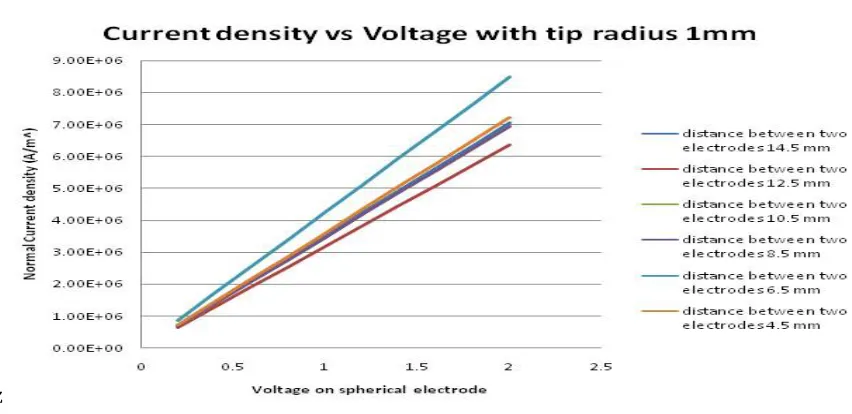
Fig 9: Current Density Vs Voltage For different values of Distance between electrodes
The above figure compares the values of normal current density for different values of spacing.
Table 1: Showing comparison of J for different values of spacing at 2V
Spacing between two electrodes(mm) Normal Current Density(MA/m^2)
4.5 7.23
6.5 8.49
8.5. 6.95
10.5 6.95
12.5 6.37
14.5 7.05
16 3.54
From Table 1 we can say that we can maximize current density if keep the spacing between two electrodes equal to 6.5mm. It is worth noticing that there is no direct relationship between the two quantities i.e. on decreasing the spacing beyond 6.5mm, the current density starts decreasing. Same thing can be noticed when spacing is increased beyond 12.5mm i.e. the current density again starts decreasing if we increase spacing beyond 12.5mm. Thus we can conclude that optimum value of electrode spacing for maximizing current density is 6.5mm.
ISSN(Online): 2319-8753 ISSN (Print): 2347-6710
I
nternational
J
ournal of
I
nnovative
R
esearch in
S
cience,
E
ngineering and
T
echnology
(An ISO 3297: 2007 Certified Organization)
Website: www.ijirset.com
Vol. 6, Issue 7, July 2017
IV. FUTURE SCOPE OF THIS WORK
Effect of Spacing can be analyzed on various other electrical quantities like no. of degrees of freedom and electrical resistance.
The material of the electrode can be changed as current density J=σ E where sigma is conductivity which mainly depends on the material applied.
Other parameters and their effect on current density can be studied. One such parameter can be width of electrode.
A research can be done on the overall size of pacemaker electrode.
REFERENCES
[1] Sandro A. P. Haddad, Richard Houben and Wouter A. Serdijn, The evolution of pacemakers: an electronics perspective, from the hand crank to advanced wavelet analysis, DISens symposium-book, 2005
[2] S. Iman Zonoori, Elaheh Nikkhah Bahrami, Zahra Bahrami, Shahin Rezvani Abrava,“Performance Analysis in Pacemaker Electrode and Study Effect Electric Resistance”, International Journal of Scientific Engineering and Technology, Volume No.3 Issue No.8, pp : 1100-1101,2014
[3] C.Frank Starmer PhD, Robert E. Whalen, Current Density and electrically induced ventricular fibrillation, Association for the Advancements of Medical Instrumentation, Vol 2, March-April 1973
[4] https://thoracickey.com/pacing-and-defibrillation-clinically-relevant-basics-for-practice/ [5] https://www.comsol.com/model/pacemaker-electrode-471