BUILT-IN DUAL FREQUENCY ANTENNA WITH AN EMBEDDED CAMERA AND A VERTICAL GROUND PLANE
S. H. Zainud-Deen
Faculty of Electronic Engineering Menoufia University
Egypt
S. M. Gaber and S. M. M. Ibrahem
Faculty of Engineering Helwan University Egypt
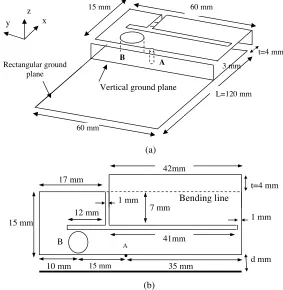
Abstract—A thin internal planar antenna for GSM/DCS with a hollow shorting cylinder suitable for integration with an embedded digital camera for a mobile phone is presented. A small vertical ground plane electrically connected to the system ground plane of the mobile phone is used. The vertical ground plane can function as an effective shield wall between the antenna and the nearby electronic elements in the mobile phone. The method of moments is used to simulate the antenna structure and calculate the radiation characteristics of the antenna.
1. INTRODUCTION
patch antenna, however allows the fringing electromagnetic (EM) fields to easily penetrate into the surrounding region of the antenna. In this case, some coupling between the antenna and the nearby electronic components will occur resulting in degrading effects on the performance of the antenna. To reduce this degrading coupling effect, an isolation distance of about 7 mm or larger between the antenna and the nearby electronic components is usually required for practical applications [3]. This isolation distance leads to an inefficient usage of the valuable board space of the system circuit board of the mobile device. In many wireless devices, a digital camera is usually embedded, preferably at the top portion of the device’s system circuit board as well and thus competing for the very limited space of the system circuit board with the internal antenna.
In this paper, a thin GSM/DCS dual-band internal patch antenna with an air-layer substrate as in [5] is presented. Hollow shorting cylinder is used to accommodate the charge-coupled device (CCD) of an embedded digital camera in a mobile phone, thus leading to a compact integration of the antenna and CCD. The shorting cylinder also serves to support the proposed antenna firmly above the grounded substrate. Small vertical ground plane electrically connected to the system ground plane of the mobile phone is presented. The vertical ground plane can function as an effective shielding wall between the antenna and the nearby RF-shielding metal case or other associated elements in a mobile phone. In this case, the internal antenna can be compactly integrated within the mobile phone without degradation of the antenna performances.
2. ANALYSIS
The simulated results in this paper are obtained using the method of moments (MoM) [12]. The radiation characteristics of the antenna starting from the total field equation:
E(r) =Ei(r) +
s
G(r/r)·J(r)ds (1)
where E(r) is the total tangential field on the surface, Ei(r) is the
incident field on the conducting surface,G(r/r) is the dyadic Green’s function, andJ(r) is the current distribution on the conducting surface
S. For a typical highly conductive structure, the induces current is flowing on the conducting surface S of the antenna and boundary conditions
whereZs(r) is the surface impedance of the conductor. From Eqs. (1)
and (2), then
Zs(r)J(r) =Ei(r) +
s
G(r/r)·J(r)ds (3)
By assuming that the current distribution is represented by a set of complete basis functions:
J(r) =
N
n
InBn(r), n= 1,2,3, . . . (4)
where,N is the number of finite terms. After some manipulations and using the test functions the same as the basis functions (Galerkin’s method), Eq. (3) becomes anN ×Nmatrix equation,
[Zmn][In] = [Vm] (5)
where
Zmn=
s
Zs(r)Bm(r)·Bn(r)ds−
s ds
s
Bm(r)·G¯(r/r)·Bn(r)ds(6)
Vm=
s
Ei(r)·Bn(r)ds (7)
The solutions of Eq. (5) are the coefficients of the expanded current distribution in Eq. (4).
In this analysis roof-top functions are used to approximate the current distribution on the antenna. A roof-top function is a ramp in the longitudinal direction and constant on the transverse direction. After the current distribution is solved, the antenna parameters can be calculated.
3. NUMERICAL RESULTS
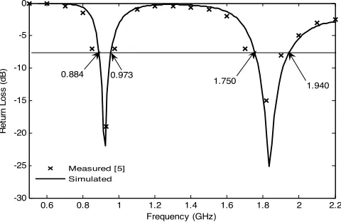
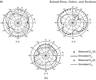
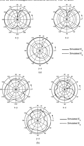
radiation characteristics of the internal GSM/DCS patch antenna for a portable mobile terminal as in [5, Figure 1] were calculated to verify the accuracy of the computer program. Figure 2 depicts the variation of the return loss in dB versus the frequency for the antenna structure. The radiation characteristics of the antenna are compared with the measurements in Figures 3 at frequency f = 925 and f = 1795 MHz. Good agreement is observed between the simulated results and the measured results. The hollow shorting cylinder of diameter 6 mm is used as a first modification for the antenna structure in [5]. The position of the feeding pin is modified as in Figure 1 to keep the same resonant frequencies approximately the same as in [5]. The effect of the hollow shorting cylinder on the return loss and on the radiation characteristics are depicted on Figures 4 and 5. The radiation patterns with and without the hollow shorting cylinder are almost identical. Figure 6 shows the simulated results of the return loss after adding the vertical plane at a distance d= 0.5 mm from the edge of the antenna
60 mm
3 mm 15 mm
A B
60 mm Rectangular ground
plane z
x y
L=120 mm t=4 mm
Vertical ground plane
(a)
41mm
10 mm 12 mm 17 mm
15 mm
7 mm
Bending line
B A
42mm
t=4 mm
1 mm 1 mm
35 mm
15 mm d mm
(b)
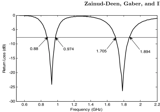
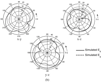
(see Figure 1). The impedance bandwidth, defined by 2.5:1 VSWR (about 7.3 dB return loss) is 94 MHz for the GSM band and 189 MHz for DCS band. Figure 7 shows the radiation patterns of the antenna at 925 MHz and 1795 MHz in different plane. Stable radiation patterns are noticed.
0.6 0.8 1 1.2 1.4 1.6 1.8 2 2.2
-30 -25 -20 -15 -10 -5 0
Frequency (GHz)
R
e
tu
rn
Los
s
(
d
B
)
0.884 0.973
1.750
1.940
Measured [5] Simulated
Figure2. Simulated and measured return loss.
10 20 30 40 50
30
210
60
240 90
270 120
300 150
330
180 φ
10 20
30 40
30
-150
60
-120 90
-90 120
-60 150
-30
180 θ
10 20
30 40
30
-150
60
-120 90
-90 120
-60 150
-30
180 θ
x-y x-z
y-z (a)
Measured E θ [5] Simulated E
θ Measured E
φ [5] Simulated Eφ
0 0
10 20
30 40
30
-150
60
-120 90
-90 120
-60 150
-30
180 θ
10 20
30 40
30
210
60
240 90
270 120
300 150
330
180 φ
10 20
30 40
30
-150
60
-120 90
-90 120
-60 150
-30
180 0θ
x-y
x-z
y-z
(b)
Measured E θ [5] Simulated E
θ Measured Eφ [5]
Simulated Eφ 0
0
Figure3. Simulated and measured radiation pattern in different planes. (a) at f = 925 MHz, (b) atf = 1795 MHz.
0.6 0.8 1 1.2 1.4 1.6 1.8 2 2.2
-30 -25 -20 -15 -10 -5 0
Frequency (GHz)
R
e
tu
rn
l
o
s
s
(
d
B
)
0.88 0.974 1.705 1.894
10 20 30 40 30 -150 60 -120 90 -90 120 -60 150 -30
180 0θ
10 20 30 40 30 210 60 240 90 270 120 300 150 330
180 0φ
10 20 30 40 50 30 -150 60 -120 90 -90 120 -60 150 -30
180 0θ
x-y x-z
y-z (b) Simulated E θ Simulated E φ 10 20 30 40 30 -150 60 -120 90 -90 120 -60 150 -30
180 0θ
10 20 30 40 30 210 60 240 90 270 120 300 150 330 180 φ 10 20 30 40 30 -150 60 -120 90 -90 120 -60 150 -30
180 0θ
x-y x-z
y-z (a) Simulated E θ Simulated E φ 0
0.6 0.8 1 1.2 1.4 1.6 1.8 2 2.2 -30
-25 -20 -15 -10 -5 0
Frequency (GHz)
R
e
tu
rn
L
o
s
s
(d
B
)
0.88 0.974 1.705
1.894
Figure6. Simulated return loss after acting the hollow shorting cylinder and vertical plate.
10 20
30 40
30
210
60
240 90
270 120
300 150
330
180 0φ
10 20
30 40
30
-150
60
-120 90
-90 120
-60 150
-30
180 0θ
10 20
30 40
30
-150
60
-120 90
-90 120
-60 150
-30
180 0θ
x-y x-z
y-z
(a)
Simulated E
θ
10 20
30 40
30
-150
60
-120 90
-90 120
-60 150
-30
180 0θ
10 20 30
40
30
210
60
240 90
270 120
300 150
330
180 0φ
10 20 30 40 50
30
-150
60
-120 90
-90 120
-60 150
-30
180 0θ
x-y x-z
y-z
(b)
Simulated E
θ
Simulated E
φ
Figure7. Simulated and measured radiation pattern in different planes after adding the hollow cylinder and vertical plate. (a) at
f = 925 MHz, (b) at f = 1795 MHz.
4. CONCLUSIONS
A built-in dual frequency antenna with an embedded camera and a vertical ground plane is investigated. A vertical-ground plane is used. Hollow shorting cylinder is proposed to embedded the digital camera inside the antenna structure. Good isolation behavior between the antenna and a nearby element such as the RF-shielding metal case inside the mobile phone has been achieved. Good radiation characteristics has been observed.
REFERENCES
2. Chien, S. L., F. R. Hsiao, Y. C. Lin, and K. L. Wong, “Planar inverted-F antenna with a hollow shorting cylinder for mobile phone with an embedded camera,”Microwave and Optical Technology Letters, Vol. 41, No. 5, 418–419, June 2004.
3. Wong, K. L., S. L. Chien, C. M. Su, and F. S. Chang, “An internal planar mobile-phone antenna with a vertical ground plane,”Microwave and Optical Technology Letters, Vol. 46, No. 6, 597–599, September 2005.
4. Wong, K. L. and Y. C. Lin, “Thin internal planar antenna for GSM/DCS/PCS/UMTS operation in a PDA phone,”Microwave and Optical Technology Letters, Vol. 47, No. 5, 423–426, December 2005.
5. Wong, K. L., Y. C. Lin, and T. C. Tseng, “Thin internal GSM/DCS patch antenna for a portable mobile terminal,” IEEE Trans.Antennas Propag., Vol. 54, No. 1, 238–241, January 2006. 6. Wong, K. L. and T. C. Tseng, “Internal patch antenna with an inset shielding metal case for mobile-device application,” Microwave and Optical Technology Letters, Vol. 48, No. 2, 220– 222, February 2006.
7. Su, C. M., K. L. Wong, B. Chen, and S. Yang, “EMC internal patch antenna integrated with a U-shaped shielding metal case for mobile device application,”Microwave and Optical Technology Letters, Vol. 48, 1157–1161, 2006.
8. Su, S. W., A. Chen, K. L. Wong, and Y. C. Lin, “Integrated internal patch antenna for umts mobile phone application,” Microwave and Optical Technology Letters, Vol. 49, No. 2, 349– 351, February 2007.
9. Abdelaziz, A. A., “Bandwidth enhansment of microstrip antenna,”Progress In Electromagnetics Research, PIER 63, 311– 317, 2006.
10. Kaya, A., “Meandered slot and slit loaded compact microstrip sntenna with integrated impedance tuning network,” Progress In Electromagnetics Research B, Vol. 1, 219–235, 2008.