Design of Level Controller Using LabVIEW
B.Suganya1, R.Swetha2, P.Sandia 3
, H.Kala 4
Assistant Professor, Department of ICE, Saranathan College of Engineering, Trichy, Tamil Nadu, India4
Student, Department of ICE, Saranathan College of Engineering, Trichy, Tamil Nadu, India123
ABSTRACT:The aim of our paper is to implement a computer based control system for a real time process. The hardware PID is replaced with software PID that has equal controlling capabilities as that of instrument. The software PID controller is applied using LABVIEW by National Instruments. We have used a myRIO for interfacing the software with the hardware. The process consists of a multi-loop Trainer kit mounted with a tank whose level has to be controlled using a feedback control loop. The flow of project execution is: The measured inputs to the designed PID will be delivered by Level transmitter. The designed PID will be generating the necessary controlling electronic signal. This signal will be acquired by myRIO. The myRIO transfers it to the I/P converter which will convert the electrical signal 4-20mA into pneumatic signal 3-15psig to actuate the control valve. This virtual PID can replace hard wired PID. By virtual PID implementation we are getting freedom of reconfiguration and flexibility of control strategy.
KEYWORDS: NI myRIO, Set point, Process variable, LabVIEW software
I.INTRODUCTION
LABVIEW (Laboratory Virtual Instrument Engineering Workbench) is a system-design platform and development environment for a visual programming language from National Instruments. The user interface is known as the front panel. You then add code using graphical representations of functions to control the front panel objects. The block diagram contains this code. In some ways, the block diagram resembles a flowchart. Users interact with the Front Panel when the program is running. Users can control the program, change inputs, and see data updated in real time.
II.MYRIO SPECIFICATION
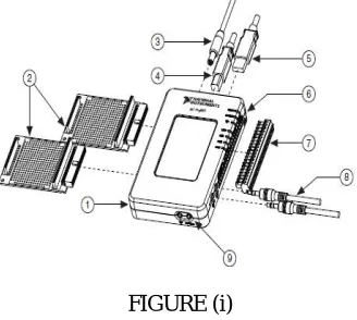
1.NI myRIO-1900 2.myRIO Expansion Port (MXP) Breakouts (One Included in Kit) 3 Power Input Cable 4 USB Device Cable 5 USB Host Cable (Not Included in Kit) 6 LEDs 7 Mini System Port (MSP) Screw-Terminal 8 Audio In/Out Cables (One Included in Kit)
9 Button 0
FIGURE (i)
I
nternational
J
ournal of
A
dvanced
R
esearch in
E
lectrical,
E
lectronics and
I
nstrumentation
E
ngineering
(An ISO 3297: 2007 Certified Organization)
Vol. 5, Issue 3, March 2016
used in real time. It consists of two expansion ports (MXP) connectors A and B which carry identical set of signals and both have 34 pins out and a mini system port (MSP) called connector C. It provides the connection with computer through USB or wireless connectivity. NI-myRIO has 3.3v, 5v, +/-15v power output.
NI-my RIO is reconfigurable and reusable teaching tool that helps students to learn a wide variety of engineering concepts as well as complete design projects. All NI reconfigurable input/output(RIO) hardware component are programmed with LABVIEW software to give engineers the ability to rapidly 4create custom timing, signal processing and control for input/output without requiring expertise in low-level hardware described languages or board-level design.NI reconfigurable hardware platforms can meet your embedded control and monitoring application challenges in a way that outperforms other off-the-self solution and eliminates the need for costly custom design.
III .MULTI PROCESS TRAINER KIT WORKING SETUP
Level control trainer is designed for understanding the basic principles of level control. The process setup consists of supply water tank fitted with pump for water circulation. The level transmitter used for level sensing is fitted on transparent process tank. The process parameter (level) is controlled by microprocessor based digital indicating controller which manipulates pneumatic control valve through I/P converter. A pneumatic control valve adjusts the water flow in to the tank. These units along with necessary piping are fitted on support housing designed fortable top mounting.
FIGURE (ii)
PROCESS DESCRIPTION:
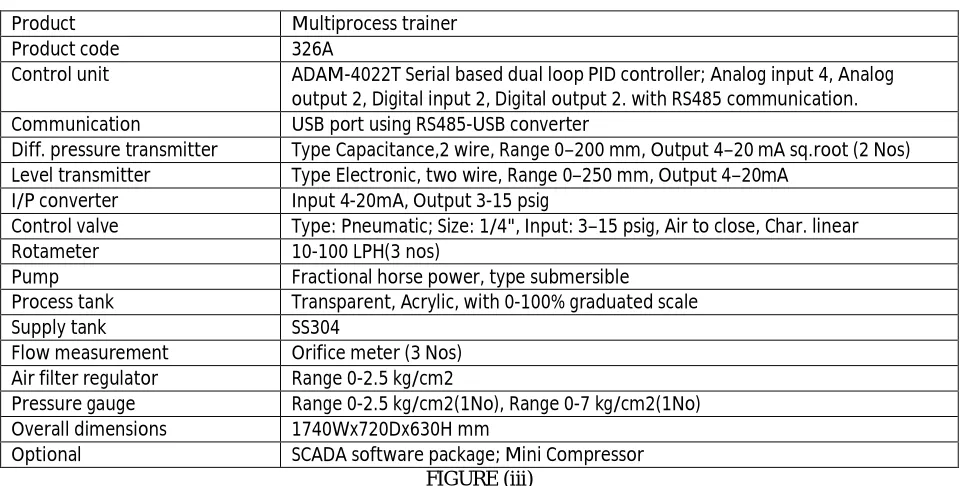
SPECIFICATION:
Product Multiprocess trainer
Product code 326A
Control unit ADAM-4022T Serial based dual loop PID controller; Analog input 4, Analog
output 2, Digital input 2, Digital output 2. with RS485 communication.
Communication USB port using RS485-USB converter
Diff. pressure transmitter Type Capacitance,2 wire, Range 0–200 mm, Output 4–20 mA sq.root (2 Nos)
Level transmitter Type Electronic, two wire, Range 0–250 mm, Output 4–20mA
I/P converter Input 4-20mA, Output 3-15 psig
Control valve Type: Pneumatic; Size: 1/4", Input: 3–15 psig, Air to close, Char. linear
Rotameter 10-100 LPH(3 nos)
Pump Fractional horse power, type submersible
Process tank Transparent, Acrylic, with 0-100% graduated scale
Supply tank SS304
Flow measurement Orifice meter (3 Nos)
Air filter regulator Range 0-2.5 kg/cm2
Pressure gauge Range 0-2.5 kg/cm2(1No), Range 0-7 kg/cm2(1No)
Overall dimensions 1740Wx720Dx630H mm
Optional SCADA software package; Mini Compressor
FIGURE (iii)
IV.PROCESS BLOCK DIAGRAM
This is the process block diagram of overall system. Level is measured by level transmitter(DPT),outputs of which is 1-5v signal. The transmitter signal s sent to LABVIEW based PID controller through my-RIO.LABVIEW based PID controller is used which generate the control signal .the control signal is the voltage which I converted to current using V to I converter circuit. The output of V to I converter to I/P converter which manipulates the input flow control valve.
Fig. 2 Throughput of receiving bits vs Maximal end to end delay
FIGURE (iv)
TRANSFER FUNCTION:
TF= .
.
.
V. ACQUIRING CIRCUIT DIAGRAM
In level Process kit, the level transmitter voltage (0 to 5v) will be measured in the above mentioned circuit.From the transmitter analog voltage the myRIO input can be connected. As the level increases corresponding transmitter output voltage is taken. In myRIO we have three ports such as port A, port B and port C. Here we are taking
COMPUTER (LABVIEW) myRIO
(ACQUIRING) LEVEL
TRANSMITTER LEVEL
PROCESS
my-RIO (GENERATING) V/I
CONVERTER(4-20mA) I/P
CONVERTER (3- 15)PSI PNUEMATIC
I
nternational
J
ournal of
A
dvanced
R
esearch in
E
lectrical,
E
lectronics and
I
nstrumentation
E
ngineering
(An ISO 3297: 2007 Certified Organization)
Vol. 5, Issue 3, March 2016
port A, where 3rd pin is the input and 6th pin is ground. Then myRIO is interfaced with the PC using LABVIEW with the help of USB cable. After that we have to build the myRIO VI which is present in the block diagram. Then right click on the block diagram and select myRIO , it shows the default icon from that we have to select the analog input . Finally we have to run the program; there the transmitter voltage can be acquired. Once the set point is reached the Boolean indicator indicates the signal.
FIGURE (v)
VI.GENERATING BLOCK DIAGRAM
The output from myRIO is 1-5V .That voltage is converted to 4-20mA using V to I converter. The current is given as input to the I/P using which the pressure is created and valve can be opened and closed accordingly
FIGURE (v)
VII. SOFTWARE AND HARDWARE CONNECTION
The voltage which is acquired by the myRIO is now generated to control the control valve in the level process. The acquired voltage is given to a comparator followed by a Proportional, Integral and Derivative (PID) controller. From the readings obtained from the level process station, the corresponding transfer function is formulated. From the transfer function the proportional gain, the integral gain and the derivative gain are calculated. These gain values are entered in the PID block which is available in the LabVIEW software. Next to it, a transfer function block is taken and the transfer function for the level process is entered in it. Hence we have formed a closed loop function for the process. Now the output generated from the closed loop is given to the myRIO. The myRIO generates the obtained output to the I-to-P converter of the process station. The I-to-P converter does the necessary control action (i.e.) when the setpoint is reached, the necessary control action is done by the closed loop and the control valve is closed when the I-to-P converter receives 20mA or 15Psi.
VIII.ACQUIRING AND GENERATING
In this program, the analog input voltage from the level process station is acquired through the analog input icon from the differential pressure transmitter (DPT). The control and simulation loop used in this program is similar to the practical control loop. The real time analog input voltage (process variable) is compared with the desired setpoint (interms of voltage) using a comparator. The error value from the comparator is given to the PID controller block. The Kc, Ʈi, Ʈd values given in the PID controller is obtained from the Z-N method of controller tuning technique. To obtain
this, the transfer function for the process is formulated from the corresponding voltage and time seconds values for each cm of level in the linear tank. The output from the PID controller is given to the analog output icon. When the
MYRIO
OUTPUT(1-5)V
I-P
CONVERTER
(3-15)PSI
V-ICONVERTERCIRC--UIT(4-20)mA
setpoint is reached, 5V is generated in the analog output indicator. Before the setpoint is reached, the corresponding intermediate voltages are displayed. For verification purpose, the real time analog input voltage is converted to corresponding level as of that in the linear tank using some conversions.
When the setpoint is reached, 5V is generated in the myRIO. That 5V is converted into the range of 4-20mA current using corresponding circuit connections. When the setpoint is reached, 5V is converted to 20mA current which is sufficient for closing the control valve of the level control process station since the control valve in the process kit is operated within 3-15Psi pressure range. When 20mA is given, 15Psi of pressure is supplied to the control valve which in turn stops the flow of water into the tank
.
FIGURE(vi) Front panel and block diagram
IX.CONCLUSION
By using LABVIEW controls, indicators and block diagram functions a virtual PID is designed and verified .This paper switches the conventional PID instrument with a virtual controller. It saves time of manufacturing instrument, since the PID logic can be designed on LABIEW in a very short period. This PID controller is flexible and easy to use. Practically this application needs no maintenance and very easy to upgrade. The experimental investigations in NI LABVIEW show that the new system developed would be highly flexible and easy in controlling the level. In real time environment for better performance of process plant it is difficult and expensive to conduct experiments directly. These results will be useful to do the required modifications in process industries for efficient control. Also the flow-level cascade control for which the soft PID is implemented is a normally used control requirement. The test results can help study the cascade control, its control using LABVIEW based PID can be used in many practical industrial applications. myRIO is used to line real time and LABVIEW with which we have successfully acquired and generated the signal
REFERENCES
[1] Mohammad A. K. Alia, Tariq M. Younes, Shebel A. Alsabbah, A Design of a PID Self-Tuning Controller Using LabVIEW Journal of Software Engineering and Applications, 2011, 4, 161-171.
[2] P. Thepsatom1 , A. Numsomran2 , DC Motor Speed Control using Fuzzy Logic based on Lab VIEW, SICE-ICASE International Joint Conference 2006 Oct. 18-21, 2006.
[3] K. V. L. P srinivas1, P Durga Prasada Rao2, “Modelling and simulation of complex, Control systems using labview,” International Journal of Control Theory and Computer Modelling, IJCTCM, VR Siddhartha Engineering College, Vijayawada, India.
[4] J. M. Jacob, “Labview graphical programming for instrumentation,” Industrial Control Electronics. Prentice-Hall International, Inc., New Jersey , U.S.A, 1989. [5] B. E. Paton, “Labview graphical programming for instrumentation,” Programming for Instrumentation. Prentice Hall PTP, New Jersey , U.S.A, 1999. [6] “Labview basics introduction,” National Instruments, Course Manual, U.S.A, 2002.