Generation of New Random PWM Pulse for
Buck Boost Converter Using LabVIEW
M. Sakthivel1, C. Krishna Kumar2, R. Uthirasamy3
PG Student, Dept. of EEE, Jansons Institute of Technology, Coimbatore, Tamilnadu, India1 Professor, Dept. of EEE, KPR Institute of Engineering and Technology, Coimbatore, Tamilnadu, India2
Associate Professor, Dept. of EEE, Jansons Institute of Technology, Coimbatore, Tamilnadu, India3
ABSTRACT: This paper addresses random pulse width modulation (RPWM) and its applications to the power electronic converters. RPWM differentiate from conventional PWM, which produces switching functions that have non deterministic variables. This paper presents new RPWM scheme developed with the help of virtual Instrumentation (VI) software. The comparative investigations of proposed RPWM scheme against the normal PWM for the buck boost converter is presented. The effectiveness of randomization on spreading the dominating frequencies that normally exist in constant frequency PWM schemes is evaluated by the power spectral density (PSD) estimations in the low-frequency range.
KEYWORDS: Power converters, random switching techniques, Virtual Instrumentation, Power Spectral Density.
I.INTRODUCTION
Power electronic converters are used to convert electrical energy from one level to another level using power semiconductor based electronic switches. The essential characteristics of these types of circuits is that the switches are operated only in one of two states either fully ON or fully OFF. The process of switching the electronic devices in power electronic converter from one state to another is called modulation. A fast switching operation generates signals with high voltage-rate (dv/dt) and high current rate (di/dt) and, consequently, disturbances over wider frequency bandwidths. These high switching frequency harmonics can have adverse effects, such as acoustic noise, mechanical vibration and electromagnetic interference. Standard pulse width modulation (PWM) schemes cause the power converter to switch in a “deterministic” manner, which results in a PWM waveform with a large fundamental voltage component with low-order harmonics suppressed. However, the harmonic power is usually concentrated at a few predictable frequencies. The use of PWM technique for the control of power converters allows adjusting the useful component of the voltage and eliminating some unwanted harmonics. Thus, it is required for power converters to provide the desired electrical functionality and to meet international standards of Electro-Magnetic Compatibility (EMC) by reducing conducted emissions. Using filtering technique to meet the better EMC standards for conducted EMI. RPWM technique is one of the effective method to spread the power spectrum over a wide frequency range while reducing its amplitudes and it constitutes a significant EMC advantages. Several RPWM techniques have been proposed recently: Randomized Carrier Frequency Modulation (RCFM) and Randomized Pulse Position Modulation (RPPM).
The RCFM technique can be mainly categorized into The Random Carrier-Frequency Modulation with Fixed Duty cycle (RCFMFD), and with variable duty cycle (RCFMVD) respectively. In the conventional randomized PWM techniques, certain switching signal parameters are randomized. The followings are the possibilities of switching signal parameters duration of the kthcycle (Tk), the duration of the on-state within the cycle (αk), duty ratio is dk=αk/Tk and the
delay from the start of the switching cycle to the turn-on within the cycle (εks), Trailing edge of the switching cycle
(εkt). In the proposed random modulation scheme trailing edge of the switching cycle (εkt) is fixed constant and delay
from the start of the switching cycle (εks) and duty ratio dk is randomized. Analytical model of power spectral density
II.RANDOMIZED SWITCHING SIGNAL
The fundamental difference between classic PWM and RPWM method is, that the power carried by the PWM signal is no longer limited to a few leading frequency that are normally controlled by the switching frequency and the modulated signal. The probability laws govern the dithering of nominal switching patterns. If the probabilistic structure is constant from one cycle to cycle, it is called stationary. If it is constant only over a block cycles, it is called as block-stationary. RPPM is similar to the classical PWM scheme with constant switching frequency. However, the position of the gate pulse is randomized within each switching period, instead of commencing at the start of each cycle. RPWM allows the pulse width to vary, but the average pulse width is equal to the required duty cycle. RCFMFD exhibits randomized switching period and constant duty cycle, while RCFMVD exhibits randomized switching period and constant pulse width. As the pulse width in RCFMVD is fixed and the switching period is randomized, the resultant duty cycle is also randomized.
Fig. 1.Switching Signal of Proposed RPWM Technique
The switching parameters shown in Fig.1 such as the duration of the kth cycle (Tk), the duration of the on-state
within this cycle (αk), duty ratio is (dk=αk/ Tk) and the delay from the start of the switching cycle to the turn-on within
the cycle (εks), Trailing edge of the switching cycle (εkt). Randomness level and the average duty cycle for all the
random modulation schemes were kept constant to maintain the desired output voltage. A1 and A2 are the magnitudes
of the switching pulses. The characteristics of the switching pulse in each modulation scheme are summarized in Table 1, with the aid of Fig. 1. The switching function g(t) has two discrete levels (namely A1 and A2), which are applicable for describing the behavior of classical DC-DC converters.
III. GENERATION OF PROPOSED RPWM
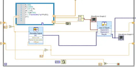
Electronic circuit requires accurate methods for evaluating circuit performance. Because of enormous complexity of modern integrated circuits, computer aided analysis of the circuits is essential and can provide information about circuit performance that is most impossible to obtain with laboratory prototype measurements. LabVIEW is a general purpose circuit program that simulates electronic circuits. LabVIEW contains model for common circuit elements, active as well as passive, and it is capable of simulating most electronic circuits. Fig.2 shows the simulation block diagram for generation of constant trailing edge random PWM signal.
Fig. 2. Simulation circuit for CTERPWM scheme
g(t)
εkt
αk
εks
Tk t
A2
The simulation block diagram consists of triangular carrier wave with variable duty cycle and dc reference voltage. Here the falling edge of the switching cycle is randomized. Fig. 3 shows the different random PWM pulses of constant trailing edges with different duty ratio is presented.
(a) (b)
(c)
Fig.3. CTERPWM signals with different duty ratio
Fig.4 Simulation circuit for Buck-Boost Converter
D1 D2
D3 D4
C1 C2 RL
Q1
LabVIEW based Random PWM
Generator
Vs L1
The simulated RPWM signal is fed to the buck boost converter circuit. The simulation circuit for buck boost converter is shown in fig.4. The simulation circuit was developed by Multisim electronic circuit simulation software and switching pulse for MOSFET is fed from labVIEW software.
IV. RANDOMNESS LEVEL
In order to investigate the effectiveness of the stochastic variable randomness level on spreading harmonic power, a randomness level for each scheme is defined. For RPPM,
(1)
where εk [ε1, ε2 ]. ε1 and ε2 are the minimum and maximum limits of the pulse positions within each cycle. ε1 is
obviously equal to zero. TS is the nominal switching period.
For RPWM,
(2)
Where αk [α1, α2 ]. Thus, the duty cycle dk varies between the minimum possible value d1 and the maximum possible
value d2 around the nominal duty cycle within the classical PWM scheme.
For proposed RPWM,
1 2 1 2 12 d d
T
Tk k
ks ks
CTERPWM
(3)where εks [εks1, εks2]. εks1, εks2 are the minimum and maximum limits of delay for start of pulse positions within each
cycle. Thus, the duty cycle dk varies between the minimum possible value d1 and the maximum possible value d2
around the nominal duty cycle within the classical PWM scheme.
V. VALIDATION OF PROPOSED METHOD
In the randomized modulation switching scheme the harmonic spectrum is random and it varies with respect to time. Therefore, it must be evaluated by an appropriate mathematical tool, Power spectrum (the Fourier transform– FT of the autocorrelation function of a signal) and not the harmonic spectrum (i.e. the FT of the signal itself). In particular, the autocorrelation function of a random process is the appropriate statistical average concerning the characterizations of random signals within the time-domain. The FT of the autocorrelation function gives the PSD and provides transformation from the time domain to the frequency-domain.
ʀ(τ) = lim
→ 1
2 ( ) ( − τ) τ (4)
Where the expectation operator E[.] take over the whole ensemble. The well known Welch’s estimation method for PSD is also implemented within Matlab software package as the "psd" function:
PSD = psd(X, NFFT, Fs, Window, NOverlap, DTrend) (5)
Fig.5 PSD Spectrum for Conventional PWM with buck boost converter
Fig.6 PSD Spectrum for proposed CTERPWM with buck boost converter
Simulated PSD results for conventional PWM scheme is shown in fig.5. In this figure it shows that in the frequency range 5MHz to 10MHz frequency spectrum crosses the 80dB/Hz. Fig.6 shows the spectrum of PSD for proposed RPWM scheme. In this figure it is clearly shows that spectrum of power density is distributed over the whole frequency range. The maximum peak of the spectrum is also limited with the range when compared with the conventional PWM method. Thus the proposed method gives limited PSD spectrum over the all frequency range.
VI. CONCLUSION
This paper has given comparative investigations of conventional PWM and proposed CTERPWM modulation schemes on the PSD estimation. It has been clearly demonstrated that all RPWM can gradually spread the discrete frequency harmonic power over the whole frequency spectrum. However, this investigation shows that proposed RPWM method gives the minimum low-frequency harmonic spectrum and, therefore, can be considered as the best choice for DC-DC converter applications. Future work is focused on implementing the proposed work in hardware working model and verify the experimental PSD and EMI measurements.
REFERENCES
[1] Y.Lai, and B.Chen, “New random pwm technique for a full-bridge dc/dc converter with harmonics intensity reduction and considering efficiency”, IEEE Transactions on Power Electronics, vol. 28, no. 11, pp. 5013-5023, 2013.
[2] KK.Tse, HS-H.Chung, SYR.Hui, and HC.So, “A Comparative Investigation on the Use of Random Modulation Schemes for DC/DC Converters”, IEEE Transactions on Industrial Electronics, vol. 47, no. 2, pp. 253-263, 2000.
[3] Krishna Kumar, C. and Nirmal Kumar, A. “Analysis of Conducted EMI with Standalone Solar powered DC Motor”, Turkish Journal of Electrical Engineering and Computer Sciences, Vol. 21, pp. 1260-1271, September 2013.
Science Department, Massachusetts Institute Technology, 1993.
[5] MM.Bech, JK.Pedersen, F.Blaabjerg, and AM.Trzynadlowski, “A methodology for true comparison of analytical and measured frequency domain spectra in random PWM converters”, IEEE Transactions on Power Electronics, vol. 14, pp. 578-586, 1999.
[6] Krishna Kumar, C.and Nirmal Kumar, A. “Power Quality Issues on DC-Bus connected Photovoltaic System”, International Journal of Green Energy, Vol. 9, No.1, pp.39-50, 2012.
[7] RL.Kirlin, MM.Bech, and AM.Trzynadlowski, “Analysis of power and power spectral density in PWM inverters with randomized switching frequency”, IEEE Transactions on Industrial Electronics, vol. 49, no. 2, pp. 486-499, 2002.
[8] G.Heinzel, A.Rudiger, and R(eds).Schilling, Spectrum and spectral density estimation by Discrete Fourier Transform (DFT), including a comprehensive list of window functions and some new flat-top windows, MAX PLANCK digital library, Germany,2002. Available from: MPG Publication Repository [15 February 2002].
[9] Krishna Kumar, C. Muhilan, P. Sathis Kumar, M. and Sakthivel, M “A New Random PWM Technique for conducted EMI Mitigation on Cuk Converter”, Journal of Electrical Engineering and Technology (JEET), Vol. 10, No.3, pp.916-924, 2015.
[10] F.Costa, and D.Magnon, “Graphical analysis of the spectra of EMI sources in power electronics”, IEEE Transactions on Power Electronics, vol. 20, no. 6, pp. 1491-1498, 2005.
[11] RW.Erickson, DC-DC power converters, Wiley, New York, 1988.